Belden GRASS VALLEY IPG-3901 Instruction Manual

IPG-3901
High Density SDI/IP Gateway
Guide to Installation and Operation
M3036-9900-132
2016-08-18

GUIDE TO INSTALLATION AND OPERATION
IPG-3901
Document History
Document Number Date of Publication Notes
3036-99M00-100 2015-10-06 Initial Release
3036-99M00-110 2016-02-23 Support for external reference added
3036-99M00-120 2016-04-27 Support for Aggregation mode added
3036-99M00-132 2016-08-18 Support for 4K/TICO added
Copyright and Trademark Notice
Copyright © 2015-2016, Grass Valley Canada. All rights reserved.
Belden, Belden Sending All The Right Signals, and the Belden logo are trademarks or registered trademarks of
Belden Inc. or its affiliated companies in the United States and other jurisdictions. Grass Valley, Miranda, IPG-3901,
iControl, and Densité are trademarks or registered trademarks of Grass Valley Canada. Belden Inc., Grass Valley
Canada, and other parties may also have trademark rights in other terms used herein.
Terms and Conditions
Please read the following terms and conditions carefully. By using IPG-3901 documentation, you agree to the
following terms and conditions.
Grass Valley hereby grants permission and license to owners of IPG-3901 to use their product manuals for their own
internal business use. Manuals for Grass Valley products may not be reproduced or transmitted in any form or by any
means, electronic or mechanical, including photocopying and recording, for any purpose unless specifically authorized
in writing by Grass Valley.
A Grass Valley manual may have been revised to reflect changes made to the product during its manufacturing life.
Thus, different versions of a manual may exist for any given product. Care should be taken to ensure that one obtains
the proper manual version for a specific product serial number.
Information in this document is subject to change without notice and does not represent a commitment on the part of
Grass Valley.
Warranty information is available in the Support section of the Grass Valley Web site (www.grassvalley.com).
Electrostatic Discharge (ESD) Protection
Electrostatic discharge occurs when electronic components are improperly handled and can result in
intermittent failure or complete damage adversely affecting an electrical circuit. When you remove and
replace any card from a frame always follow ESD-prevention procedures:
•Ensure that the frame is electrically connected to earth ground through the power cord or any other means if
available.
•Wear an ESD wrist strap ensuring that it makes good skin contact. Connect the grounding clip to an unpainted
surface of the chassis frame to safely ground unwanted ESD voltages. If no wrist strap is available, ground
yourself by touching the unpainted metal part of the chassis.
•For safety, periodically check the resistance value of the antistatic strap, which should be between 1 and
10 megohms.
•When temporarily storing a card make sure it is placed in an ESD bag.
•Cards in an earth grounded metal frame or casing do not require any special ESD protection.

GUIDE TO INSTALLATION AND OPERATION
IPG-3901
Recycling
Visit www.grassvalley.com for recycling information.
Certification and Compliance
Safety of Laser Modules
This equipment incorporates modules containing Class 1 lasers. These modules are certified by the
manufacturer to comply with:
•IEC/EN 60825-1 Safety of laser products
•IEC 60950-1 Safety of information technology equipment
Restriction on Hazardous Substances (RoHS)
IPG-3901
部件名称 Part name
有毒有害物质或元素 (Toxic or Hazardous Substances and Elements)
铅(Pb) 汞(Hg) 镉(Cd) 六价铬
(Cr6) 多溴联苯
(PBB) 多溴二苯
(PBDE)
电缆及电缆组件 Cables and Cable Assemblies O O O O O O
电路模块 Circuit Modules X O O O O O
组装风扇 Fan Assemblies X O O O O O
IPG-3901-3DRP, IPG-3901-3TRP
部件名称 Part name
有毒有害物质或元素 (Toxic or Hazardous Substances and Elements)
铅(Pb) 汞(Hg) 镉(Cd) 六价铬
(Cr6) 多溴联苯
(PBB) 多溴二苯
(PBDE)
电路模块 Circuit Modules X O O O O O
O: 表示该有毒有害物质在该部件所有均质材料中的含量均在SJ/T 11363-2006规定的限量要求以下。
O: Indicates that this toxic or hazardous substance contained in all of the homogeneous materials for this part is below the limit
requirement in SJ/T11363-2006.
X: 表示该有毒有害物质至少在该部件的某一均质材料中的含量超出SJ/T 11363-2006规定的限量要求。
X: Indicates that this toxic or hazardous substance contained in at least one of the homogeneous materials for this part is above
the limit requirement in SJ/T11363-2006.
技术条款解释:
此声明所依据之数据由Grass Valley环境管理部门向我们的部件供应商获取。Grass Valley 公司相信此信息的正确性,但由于数据
来源于公司外部,我们无法保证它的完整和准确。所有这些特性可能在未获通知的情况下更改。
Technical explanations:
This statement is based on the information provided by our suppliers of components and collected through Grass Valley’s
environmental management system. Grass Valley believes this environmental information to be correct but cannot guarantee its
completeness or accuracy as it is based on data received from sources outside our company. All specifications are subject to
change without notice.

GUIDE TO INSTALLATION AND OPERATION
IPG-3901
Electromagnetic Compatibility
This equipment has been tested for verification of compliance with FCC Part 15, Subpart B requirements for
Class A digital devices.
NOTE: This equipment has been tested and found to comply with the limits for a Class A digital device, pursuant to
part 15 of the FCC Rules. These limits are designed to provide reasonable protection against harmful interference
when the equipment is operated in a commercial environment. This equipment generates, uses, and can radiate
radio frequency energy and, if not installed and used in accordance with the instruction manual, may cause harmful
interference to radio communications. Operation of this equipment in a residential area is likely to cause harmful
interference in which case the user will be required to correct the interference at his own expense.
This equipment has been tested and found to comply with the requirements of the EMC directive
2004/108/CE:
•EN 55022 Class A radiated and conducted emissions
•EN 61000-3-2 Harmonic current emission limits
•EN 61000-3-3 Voltage fluctuations and flicker limitations
•EN 61000-4-2 Electrostatic discharge immunity
•EN 61000-4-3 Radiated electromagnetic field immunity – RF
•EN 61000-4-4 EFT immunity
•EN 61000-4-5 Surge immunity
•EN 61000-4-6 Conducted immunity
•EN 61000-4-8 EMP immunity
•EN 61000-4-11 Voltage-dips, short-interruption and voltage variation immunity

GUIDE TO INSTALLATION AND OPERATION
IPG-3901
Table of Contents
1IPG-3901 High Density SDI/IP Gateway for Densité 3 Platform.............................................1
1.1 Introduction ......................................................................................................................................... 1
1.2 Features.............................................................................................................................................. 1
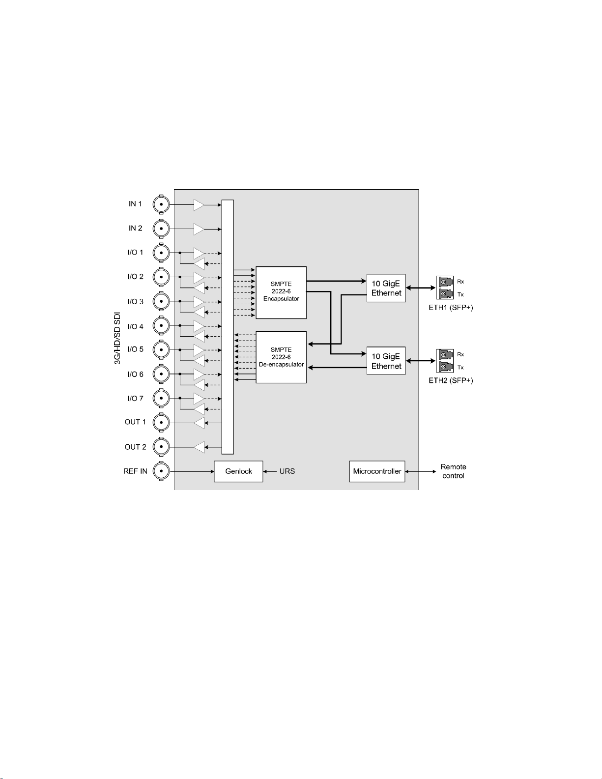
1.3 Functional Block Diagram................................................................................................................... 2
1.4 Front Card-edge Interface................................................................................................................... 3
2Installation................................................................................................................................4
2.1 Installation of Rear Connector Panels ................................................................................................ 4
2.2 IPG-3901 Card Installation.................................................................................................................. 4
2.3 Rear Panels and Connectors.............................................................................................................. 5
2.3.1 Images of Rear Panel Connectors......................................................................................... 5
2.3.2 Summary of rear panel connections...................................................................................... 5
2.3.3 Details of rear panel connections .......................................................................................... 6
3User Interface...........................................................................................................................7
3.1 Control options.................................................................................................................................... 7
3.2 Card-Edge Status LED ....................................................................................................................... 7
4Local control using the Densité frame control panel ............................................................8
5Remote control using iControl................................................................................................9
5.1 The iControl graphic interface window................................................................................................ 9
5.2 Gateway Config panel....................................................................................................................... 12
5.2.1 Gateway Config panel – System tab ................................................................................... 12
5.2.2 Gateway Config panel – Gateways tab ............................................................................... 13
5.3 Network Config panel........................................................................................................................ 16
5.3.1 Network Config panel – Settings tab ................................................................................... 16
5.3.2 Network Config panel – Status tab ...................................................................................... 17
5.3.3 Network Config panel – Statistics tab.................................................................................. 17
5.4 Gateway Status panel....................................................................................................................... 18
5.5 TICO Panel ....................................................................................................................................... 18
5.5.1 Advanced tab....................................................................................................................... 19
5.5.2 Config tab............................................................................................................................. 20
5.5.3 TICO Encoder monitoring .................................................................................................... 22
5.5.4 Metadata (including audio) when TICO is in use................................................................. 22
5.6 Reference Panel ............................................................................................................................... 23
5.7 Test panel ......................................................................................................................................... 24
5.8 Options Panel.................................................................................................................................... 25
5.9 Factory/Presets Panel....................................................................................................................... 25
5.9.1 Factory................................................................................................................................. 26
5.9.2 Profiles ................................................................................................................................. 26
5.10 Alarm Config Panel........................................................................................................................... 29
5.11 Info Panel.......................................................................................................................................... 31
5.11.1 Info Panel – Info tab............................................................................................................. 31
5.11.2 Info Panel – Technical Support tab...................................................................................... 33
6Specifications.........................................................................................................................34

GUIDE TO INSTALLATION AND OPERATION
IPG-3901
7Contact Us..............................................................................................................................35
Grass Valley Technical Support.................................................................................................................35
Corporate Head Office................................................................................................................................35
ANNEX 1 – Local Menu ...............................................................................................................36
ANNEX 2 – Firmware upgrading.................................................................................................39
ANNEX 3 – Block Diagrams of TICO Models .............................................................................41

GUIDE TO INSTALLATION AND OPERATION
IPG-3901 | 1
1 IPG-3901 High Density SDI/IP Gateway for Densité 3 Platform
1.1 Introduction
The Densité IP Gateway (IPG-3901) plug-and-play module from Grass Valley, a Belden Brand, is a 3 RU module for
the Densité 3 frame that offers bidirectional IP/SDI conversion. The Gateway operates with 10 GigE SMPTE 2022-6
video-over-IP, supporting 4K UHD/3G/HD/SD-SDI formats.
With the addition of intoPIX TICO mezzanine encoding and decoding option on the gateway, customers have a
convenient way to add 4K to their workflow and move 4K across the production facility. TICO mezzanine compression
is visually lossless 4:1 compression, which is lightweight and fast, perfectly suitable for live production. The IPG-3901
with purchasable TICO option provides either two (2) encodes OR two (2) decodes OR one (1) encode and one (1)
decode per card.
The gateways support any mix of 3G/HD/SD-SDI production workflows over IP networks. With bidirectional I/O in
combinations of 5 in/6 out or 6 in/5 out, the cards offer full redundancy in either unicast or multicast workflows to
ensure uninterrupted service.
In addition, you also have the choice to use the second ethernet port for aggregation instead of redundancy, providing
20 GigE of bidirectional bandwidth over two 10 GigE ports, increasing the capability to transport 6 in/5 out or 5 in/6 out
3G signals per IPG card. It also lets you transport more HD/SD signals in one direction taking advantage of the
bidirectional configuration of 7 BNC I/O, providing up to 9 in/2 out or 2 in/9 out. Based on the proven Densité modular
framework of over 100 functional cards, the flexible, space-efficient IPG-3901 cards accommodate a gradual adoption
of IP production elements into broadcasting workflows, while protecting operational methods and investment in
installed equipment. With flexibility to configure up to 6 IPG-3901 modules per Densité 3 frame and with each IPG-
3901 module carrying 11 HD or 6 3G gateways, the Densité 3 platform scales to a density of 66 HD or 36 3G
gateways in a 3 RU frame. In the new Densité 3+ FR4 frame, up to12 IPG-3901 modules can be installed giving a
density of 132 HD or 72 3G gateways in a 4 RU frame. This means space- and cost-efficient scaling – today and
tomorrow.
The Densité IP Gateway can be controlled by the advanced GV Convergent SDN platform, offering unified control
across COTS IP switches and SDI routing/processing infrastructures, as well as by the proven iControl systems.
1.2 Features
•High density configuration:
- Up to 11 gateways per card/66 HD/33 3G gateways per RU in redundancy mode
- Up to 66 3G gateways per RU in aggregation mode
•De-encapsulate full bandwidth uncompressed SMPTE 2022-6 to SDI
•Encapsulate SDI into full bandwidth uncompressed SMPTE 2022-6 IP
•Bidirectional transport of SD/HD/3G-SDI video signal over 10 GigE link
•Full 1+1 stream redundancy with automatic change-over link to avoid service interruption
•New aggregation mode that provides a total IP bandwidth of 20 GigE, providing higher 3G transmission
capability per IPG card such as the transfer of 4K UHD uncompressed over a 4K link on a single IPG
•Bidirectional I/O for 2 inputs, 2 outputs and 7 bidirectional I/Os for up to 11 streams
•Flexible SD/URS reference input
•Compatible with Densité 3, 3+ and GV Node platforms
•Integrates with iControl and GV Convergent SDN control frameworks
•IGMPv3 support for IP inputs
•Supports unicast and multicast signals
•Features dual-network interfaces supporting 10 GigE SFP+:
- Short range multi-mode optical.
- Long range single-mode optical.

GUIDE TO INSTALLATION AND OPERATION
2| IPG-3901
•TICO 4K 1-wire option:
- IPG-3901-OPT-TICO — this is a purchasable option that adds dual TICO codec option for 4K 1-wire support
- 2-Sample Interleave/Quad Split (2SI/SDQS) 4K link I/O support
- Simultaneous 3G/HD/SD and 4K
- TICO is intoPIX Profile 1 with visually lossless 4:1 low-latency compression
- Flexible configuration of 2 encoders or 2 decoders or 1 encoder and 1 decoder
- 3G monitoring of 4K UHD signals
1.3 Functional Block Diagram
Figure 1-1 IPG-3901 Functional Block Diagram

GUIDE TO INSTALLATION AND OPERATION
4| IPG-3901
2 Installation
2.1 Installation of Rear Connector Panels
Grass Valley Densité-series cards are each associated with a rear connector panel, which must be installed in the
Densité frame before the card can be inserted.
The IPG-3901 card is designed to fit into Grass Valley’s Densité-3 and Densité 3+ frames. Two different rear
connector panels are available:
•IPG-3901-3TRP Triple-slot-width panel for Densité-3
•IPG-3901-3+DRP Double-slot-width panel for Densité-3+FR1 and Densité-3+FR4
See section 2.3 for details of the signal connections available on these panels.
All cards and rear panels can be installed with the frame power on. The card has connectors that plug into a mid-
frame mother board for distribution of power and for connection to the controller card, and a second connector that
plugs directly into the rear connector panel for input and output.
The rear connector panel must be installed with the card out of the frame.
•To remove an existing card from the slot, tilt the swivel handle on the front of the card to lever the
connectors apart, then use the handle to pull the card straight out of the slot.
To install the connector panel:
1. If a card is installed in the slot whose rear panel is being changed, remove it as described above.
2. Remove the existing panel (either blank or belonging to an existing card that is being changed) by releasing the
captive screw(s) at the bottom (Densité 3 or Densité 3+ FR4) or side (Densité 3+ FR1) of the panel.
3. Position the new panel and secure it in place with the captive screw(s) at the bottom or side.
2.2 IPG-3901 Card Installation
Once a matching rear connector panel is in place, install the IPG-3901 card as follows:
1. Open the front panel of the frame.
2. Slide the IPG-3901 card into the slot and push gently on the handle to seat the connectors.
•When using a triple-slot-width rear panel in a Densité-3 frame, the card should be inserted into the
rightmost of the three slots.
•When using a double-slot-width rear panel in a Densité-3+ FR1 frame, the card should be inserted into the
lower of the two slots.
•When using a double-slot-width rear panel in a Densité-3+ FR4 frame, the card should be inserted into the
rightmost of the two slots.
Inserting the card into the wrong slot will not damage the card, and will be flagged by the on-card status LED
flashing red to indicate that there is no connection to the rear panel.
3. Close the front door of the frame.

GUIDE TO INSTALLATION AND OPERATION
IPG-3901 | 5
2.3 Rear Panels and Connectors
2.3.1 Images of Rear Panel Connectors
The two available rear panels are shown in the figure. Details of
the inputs and outputs are described below.
NB – references to MADI on the labels for I/O 1, 3, 4 and 7 are
for future use.
2.3.2 Summary of rear panel connections
IPG-3901-3TRP
IPG-3901-3+DRP
Double-slot-width panel for Densité 3+ FR1 and FR4 frames
♦
Triple-slot-width panel for Densité 3 frame
♦
CONNECTORS
Reference IN
1
1
3G/HD/SD SDI IN
2
2
3G/HD/SD SDI OUT
2
2
3G/HD/SD SDI I/O configurable 7 7
10 GigE Ethernet on fiber (SFP+) 2 2
.
Figure 2-1 IPG-3901 Rear Panels

GUIDE TO INSTALLATION AND OPERATION
6| IPG-3901
2.3.3 Details of rear panel connections
REF IN – External reference
Connect an NTSC or PAL reference signal (SMPTE 170M / SMPTE 318M / ITU 624-4 black burst)
3G/HD/SD IN – Serial digital 3G/HD/SD inputs
Connect serial digital video signals, conforming to the SMPTE 425M standard for 3G input signals, SMPTE 292M
standard for HD input signals or SMPTE 259M standard for SD input signals, to the connectors labeled 3G/HD/SD IN
1 and IN 2.
3G/HD/SD OUT – Serial digital video outputs
The IPG-3901 provides two 3G/HD/SD SDI video outputs on the connectors labeled 3G/HD/SD OUT 1 and 2. The
SDI video signal conforms to the input standard. The same signal is carried on both outputs.
3G/HD/SD SDI I/O – Serial digital 3G/HD/SD input or output (configurable)
Seven configurable I/O are provided. The SDI signal requirements are the same as those for the dedicated inputs and
outputs as described above.
10 GbE ETH – 10 GigE Ethernet on fiber (SFP+ Interfaces)
Two 10 Gb Ethernet interfaces (each with Tx and Rx) on optical fiber or twinax cable. SFP+ modules and matching
fiber or electrical connectors are required for the interface.

GUIDE TO INSTALLATION AND OPERATION
IPG-3901 | 7
3 User Interface
3.1 Control options
The IPG-3901 can be controlled in two different ways:
•The local control panel and its push-buttons can be used to move through a menu of status reports (see section
4).
•Grass Valley’s iControl system can be used to access the card’s operating parameters from a remote computer,
using a convenient graphical user interface (GUI) (see section 5).
3.2 Card-Edge Status LED
The status monitor LED is located on the front card-edge of the IPG-3901, and is visible through the front access door
of the DENSITÉ 3 frame. This multi-color LED indicates the status of the IPG-3901 by color, and by flashing/steady
illumination.
The chart shows how the various error conditions that can be flagged on the IPG-3901 affect the LED status.
•If a cell is gray, the error condition cannot cause the LED to assume that status
•If more than one LED status is possible for a particular error condition, the status is configurable.
See Alarm Config Panel for details.
•The factory default status, if available, is shown by a
The LED will always show the most
severe detected error status that it is
configured to display, and in the chart
error severity increases from left to right,
with green representing no error/disabled,
and flashing red the most severe error.
If the LED is Flashing Yellow, it means
that the card is selected for local control
using the Densité frame’s control panel.
See section 4 for details.
Error Condition
LED Status
Green Yellow Red
Flashing
Red
Hardware failure – cooling fans
Wrong or missing Rear
Ethernet Port 1 Link Status
Ethernet Port 2 Link Status
Internal test pattern enabled
Overall Gateway Status

GUIDE TO INSTALLATION AND OPERATION
8| IPG-3901
4 Local control using the Densité frame control panel
There are two types of local control panel:
Panel type Frame models Appearance
Physical Densité-3, Densité-3+FR1,
Touch screen Densité 3+FR4, GV Node
The local control panel is fastened to the front of the controller card.
•The physical panel is accessed by opening the front door of the frame.
•The touch screen panel is accessed through an aperture in the frame door.
The panel consists of a display capable of displaying two lines of text, each 16 characters in length, and four
pushbuttons. The functionality of the pushbuttons is as follows:
[+] [–] Used for menu navigation and value modification
[SELECT] Gives access to the next menu level. When a parameter value is shown, pushing this button once
enables modification of the value using the [+] and [–] buttons; a second push confirms the new value
[ESC] Cancels the effect of parameter value changes that have not been confirmed; pushing [ESC] causes the
parameter to revert to its former value.
Pushing [ESC] moves the user back up to the previous menu level. At the main menu, [ESC] does not
exit the menu system. To exit, re-push the [SELECT] button for the card being controlled.
If no controls are operated for 30 seconds, the controller reverts to its normal standby status, and the selected card’s
STATUS reverts to its normal operating mode.
To assign the local control panel to the IPG-3901:
•Physical Panel: Push the SELECT button on the IPG-3901 card edge (see Section 1.4)
•Touch-screen panel: In the home screen, touch the virtual button corresponding to this IPG-3901
The STATUS LED on the IPG-3901 flashes yellow, and the touch-screen status shows yellow for the IPG-3901.
Use the control panel buttons to navigate through the menu, as described above.
•The complete menu structure is shown in ANNEX 1 – Local Menu, beginning on page 36.

GUIDE TO INSTALLATION AND OPERATION
IPG-3901 | 9
5 Remote control using iControl
The IPG-3901 can be remotely controlled using Grass Valley’s iControl system.
•This manual describes the control panels associated with the IPG-3901 and their use.
•Please consult the iControl User’s Guide for information about setting up and operating iControl.
In iControl Navigator or iControl Websites, double-click on the IPG-3901 icon to open the control panel.
5.1 The iControl graphic interface window
The basic window structure for the IPG-3901 is shown in figure 5.1. The window identification line gives the card type
(IPG-3901) and the slot number where the card is installed in its Densité frame.
There are four main sections in the window itself, as identified in the figure:
Section 1. The top section displays eight icons on the left. These icons report different statuses such as card
communication status, gateway status, health status, and card operation mode.
Icon # 1 2 3 4 5 6 7 8
Move the mouse over an icon and a status message appears below the icon providing additional information.
If there is an error, the error status message appears in the message area without mouse-over.
•If there are multiple errors, the error messages cycle so all can be seen
1
2
3
Figure
5-1 IPG-3901 iControl graphic interface window
4

GUIDE TO INSTALLATION AND OPERATION
10 | IPG-3901
•The icon whose status or error message is shown is highlighted with a mauve background
The table below describes the various status icons that can appear, and how they are to be interpreted.
•In cases where there is more than one possible interpretation, read the error message in the iControl window to
see which applies.
Table – iControl Status Icon interpretation
Icon #1 – Manual Card Configuration
(green)
Remote card control activated. The iControl interface can be used to operate the card.
(yellow)
Local card control active, The card is being controlled using the Densité frame control
panel, as described in section 4. Any changes made using the iControl interface will have
no effect on the card.
Icon #2 – Gateway status
(green)
All gateways are OK.
(red)
At least one gateway is down.
Icon #3 – SDI Input Status
(green)
All SDI inputs detected and valid.
(red)
At least one SDI input is in error.
Reference mismatch.
Video/TRS error.
Icon #4 – Reference Status
(green)
Reference present, supported and locked.
(red)
Reference missing.
Unsupported format or format mismatch.
Not locked.
(gray)
No reference.

GUIDE TO INSTALLATION AND OPERATION
IPG-3901 | 11
Icon #5 – ETH1 Status
(green)
IP link up and active.
(red)
No link (port down).
Icon #6 – ETH2 Status
(green)
IP link up and active.
(red)
No link (port down).
(gray)
Ethernet port not used.
Icon #7 – Health Monitoring
(green)
Hardware OK.
(red)
Hardware Health Monitoring (Hardware fault detected).
If this icon appears flashing red, you need to call Technical Support
Icon #8 – Operation Mode
(green)
Operation mode: process – normal processing of the input signal.
(yellow)
Operation mode: Enabled, but no signal to process.
(yellow)
Operation mode: TEST – color bar and audio test tones enabled on at least one gateway.
Section 2. The left portion of the window contains selection buttons for all of the individual panels, which become
highlighted when they are selected. The main window section (3) then displays the selected panel, all of which are
described in detail below.
Section 3. The main section displays the panel selected in section 2. It may contain multiple tabs to access any
appropriate sub-panels.
Section 4. The lower left corner of the window identifies the Preset currently in use or “Custom” if none is applicable.

GUIDE TO INSTALLATION AND OPERATION
12 | IPG-3901
5.2 Gateway Config panel
5.2.1 Gateway Config panel – System tab
Receiver FIFO Level (Packets):
This setting determines the number of packets
retained in the input buffer (FIFO).
Generally, IP data streams passing through a
network with multiple switches will suffer from
“packet jitter”, which must be processed out in a
buffer before conversion to a continuous SDI video
signal. If the necessary packets have not been
received before conversion, dropouts will appear in
the video. The larger the buffer, the more likely all
the necessary packets will have been received, but
the buffer adds latency to the processing, which is
not desirable.
The object is to achieve error-free video with the lowest buffer size.
Use the slider, or type directly into the data box, to set the buffer size.
SDI Output on Error: Specify the SDI output behavior when the related gateway is on error.
Mode Behavior
Kill Turn the output OFF [DEFAULT]
Configurable
color slate Output a signal in the appropriate format, with the picture being a full-screen color as shown in the sample box
beside the pulldown.
The color is configurable:
1. Click on the color sample to open the Color Selection window.
2. In the Color Selection window, use the sliders, or type directly into the data boxes, to select a color.
Component Range Default
Y 1-254 16
Cb 1-254 128
Cr 1-254 128
3. If the selected color is an invalid system color it will be flagged in the Color Selection window and in the
color sample box.
4. Select Default to choose the system default color (Black: 12, 128, 128) and leave the Color Selection
window open.
5. Select Apply to accept the selected color and leave the Color Selection window open.
6. Select OK to accept the selected color and close the Color Selection window.
7. Select Cancel to close the Color Selection window without making changes.
Note – On SDI-to-IP, the IP stream is automatically killed when the related gateway is on error.
Receiver FIFO level
Range: 3 to 32 packets
Default: 4 packets
Figure
5-2 Gateway Config - System

GUIDE TO INSTALLATION AND OPERATION
IPG-3901 | 13
5.2.2 Gateway Config panel – Gateways tab
This tab shows the current configuration of all gateways on the card, and provides controls to modify their
configuration. The contents of the tab are affected by two settings made in other panels.
TICO Status (see Section 5.5 - TICO Panel)
TICO option not
activated. This Gateways tab shows the 11 gateways associated with the 11 SDI I/O available on the rear
panel. No TICO information is displayed.
TICO option
activated. Two additional TICO gateways are shown at the bottom of the table. They will be configured as
ENC or DEC depending on the TICO model in use.
TICO enabled. Depending on the TICO model in use, and whether an ENC or DEC is enabled ON, as many as
8 of the 11 original gateways are reserved for TICO Link I/O, and cannot be configured in this
tab. See TICO link assignment table for detailed information.
ETH2 Operation Mode (see Section 5.3.1 - Network Config Panel - Settings tab)
OFF All gateways use ETH1 port.
Aggregation ETH port for each gateway is selectable – ETH1 or ETH2.
Redundancy Each gateway uses both ETH1 and ETH2 with identical stream addresses.
See Figure 5-3 for a view of the complete tab, showing a typical configuration with TICO active and enabled.
Actions available on the tab:
•Enable/Disable a gateway by clicking the selection checkbox in the leftmost column (“En”) of the table.
•Edit the configuration of a gateway by selecting and typing directly into the table. See description below.

GUIDE TO INSTALLATION AND OPERATION
14 | IPG-3901
SDI I/O: Each Gateway (except the TICO gateways) is
linked to a physical SDI I/O via a connector on the rear
panel. In the SDI I/O column, we have the physical SDI
I/O name on the 1st line and the gateway name on the
2nd line. The gateway name can be edited – select the
text and type a new name.
Dir.: The arrow shows the direction of signal flow
between SDI and IP through the gateway.
•There are two fixed Gateways that convert SDI to
IP Stream – SDI IN 1 and SDI IN 2.
•There are two fixed Gateways that convert IP
Stream to SDI – SDI OUT 1 and SDI OUT 2.
•The remaining seven Gateways are linked to bi-
directional SDI IOs – SDI IN/OUT 1 to 7. Each of
them can be set as either SDI-to-IP or IP-to-SDI.
Click on the arrowhead and set the direction from
the dropdown.
•TICO ENC gateways are SDI to IP.
•TICO DEC gateways are IP to SDI.
Stream Address:
•When ETH2 Operation mode is set to OFF or
Aggregation, we only have one IP stream
associated with the Gateway.
•When ETH2 Operation mode is set to
Redundancy, we have two IP streams associated
with the Gateway – Primary Stream and
Redundancy stream. The gateway will be linked to
the primary stream when it is valid. If the main
stream is in error, the gateway will fall back to the redundancy stream. The fallback may generate an error on
the SDI output.
Stream Port: Shows the port associated with the stream. Edit the port by selecting the text and typing a new value.
IGMPv3 Source: On IP-to-SDI we have an additional setting: IGMPv3 source. This is used when receiving multicast
streams. In this protocol, the card deals with a switch to subscribe to one or many streams that are coming from
different IP addresses.
•When receiving multicast streams, the “stream address” is used to talk to a “group” while the “IGMPv3 source”
indicates the exact source from which we want to receive the stream.
•When receiving unicast streams, or when not using IGMPv3, set this field to 0.0.0.0.
ETH port.: This column shows the ETH port on which we are receiving or transmitting an IP stream.
•When the ETH2 port is not used (ETH2 Operation mode = OFF) this column is hardcoded to ETH1.
•When the ETH2 port is used to send or receive more IP Streams (ETH2 Operation mode = Aggregation),
ETH port has to be set to either ETH1 or ETH2.
•When the ETH2 port is used for redundancy (ETH2 Operation mode = Redundancy), the primary stream is
always received from or sent to ETH1 and the redundant stream is always received from or sent to ETH2
Format: This column specifies the SDI format permitted on this gateway – SD, HD or 3G. To change the format, click
on the current format value, and select a new value from the drop-down (SD, HD, 3G).
•Note that TICO gateways, and gateways assigned for TICO monitoring, are forced to 3G.
Figure
5-3 Gateway Config panel – Gateways tab
Aggregation
mode with 2 TICO encoders enabled
Other manuals for GRASS VALLEY IPG-3901
1
Table of contents
Other Belden Gateway manuals
Popular Gateway manuals by other brands

Dinstar
Dinstar MTG1000-4E1/T1 manual

Ruijie Networks
Ruijie Networks RG-EasyGate Series Hardware installation manual

RTA
RTA 460ETCQT-NNA4 Product user guide

Weidmüller
Weidmüller IE-GW-MB-2TX-1RS232/485 Hardware installation guide

Multitech
Multitech MultiVOIP MVP200 quick start guide

D-Link
D-Link DG-102S datasheet

Yeastar Technology
Yeastar Technology NeoGate TA410 installation guide

AT&T
AT&T NVG599 Self-installation guide

Artila
Artila Matrix-752 Hardware guide

Rohde & Schwarz Topex
Rohde & Schwarz Topex MobiLink IP user manual

AT&T
AT&T U-verse TV installation guide

Sun Oracle
Sun Oracle Sun Network QDR InfiniBand Gateway Switch installation guide