Belden GRASS VALLEY IPG-3901 Instruction Manual

IPG-3901
High Density SDI/IP Gateway
Guide to Installation and Operation
M3036-9900-100
2015-10-06

GUIDE TO INSTALLATION AND OPERATION
IPG-3901
Document History
Document Number Date of Publication Notes
3036-99M00-100 2015-10-06 Initial Release
Copyright and Trademark Notice
Copyright © 2015, Grass Valley USA, LLC. All rights reserved.
Belden, Belden Sending All The Right Signals, and the Belden logo are trademarks or registered trademarks of
Belden Inc. or its affiliated companies in the United States and other jurisdictions. Grass Valley USA, LLC, Miranda,
IPG-3901, iControl, and Densité are trademarks or registered trademarks of Grass Valley USA, LLC. Belden Inc.,
Grass Valley USA, LLC, and other parties may also have trademark rights in other terms used herein.
Terms and Conditions
Please read the following terms and conditions carefully. By using IPG-3901 documentation, you agree to the
following terms and conditions.
Grass Valley hereby grants permission and license to owners of IPG-3901 to use their product manuals for their own
internal business use. Manuals for Grass Valley products may not be reproduced or transmitted in any form or by any
means, electronic or mechanical, including photocopying and recording, for any purpose unless specifically authorized
in writing by Grass Valley.
A Grass Valley manual may have been revised to reflect changes made to the product during its manufacturing life.
Thus, different versions of a manual may exist for any given product. Care should be taken to ensure that one obtains
the proper manual version for a specific product serial number.
Information in this document is subject to change without notice and does not represent a commitment on the part of
Grass Valley.
Warranty information is available in the Support section of the Grass Valley Web site (www.grassvalley.com).
Electrostatic Discharge (ESD) Protection
Electrostatic discharge occurs when electronic components are improperly handled and can result in
intermittent failure or complete damage adversely affecting an electrical circuit. When you remove and
replace any card from a frame always follow ESD-prevention procedures:
•Ensure that the frame is electrically connected to earth ground through the power cord or any other means if
available.
•Wear an ESD wrist strap ensuring that it makes good skin contact. Connect the grounding clip to an unpainted
surface of the chassis frame to safely ground unwanted ESD voltages. If no wrist strap is available, ground
yourself by touching the unpainted metal part of the chassis.
•For safety, periodically check the resistance value of the antistatic strap, which should be between 1 and
10 megohms.
•When temporarily storing a card make sure it is placed in an ESD bag.
•Cards in an earth grounded metal frame or casing do not require any special ESD protection.
Recycling
Visit www.grassvalley.com for recycling information.

GUIDE TO INSTALLATION AND OPERATION
IPG-3901
Certification and Compliance
Safety of Laser Modules
This equipment incorporates modules containing Class 1 lasers. These modules are certified by the
manufacturer to comply with:
•IEC/EN 60825-1 Safety of laser products
•IEC 60950-1 Safety of information technology equipment
Restriction on Hazardous Substances (RoHS)
IPG-3901
部件名称 Part name
有毒有害物质或元素 (Toxic or Hazardous Substances and Elements)
铅(Pb) 汞(Hg) 镉(Cd) 六价铬
(Cr6) 多溴联苯
(PBB) 多溴二苯
(PBDE)
电缆及电缆组件 Cables and Cable Assemblies O O O O O O
电路模块 Circuit Modules X O O O O O
组装风扇 Fan Assemblies X O O O O O
IPG-3901-3DRP, IPG-3901-3TRP
部件名称 Part name
有毒有害物质或元素 (Toxic or Hazardous Substances and Elements)
铅(Pb) 汞(Hg) 镉(Cd) 六价铬
(Cr6) 多溴联苯
(PBB) 多溴二苯
(PBDE)
电路模块 Circuit Modules X O O O O O
O: 表示该有毒有害物质在该部件所有均质材料中的含量均在SJ/T 11363-2006规定的限量要求以下。
O: Indicates that this toxic or hazardous substance contained in all of the homogeneous materials for this part is below the limit
requirement in SJ/T11363-2006.
X: 表示该有毒有害物质至少在该部件的某一均质材料中的含量超出SJ/T 11363-2006规定的限量要求。
X: Indicates that this toxic or hazardous substance contained in at least one of the homogeneous materials for this part is above
the limit requirement in SJ/T11363-2006.
技术条款解释:
此声明所依据之数据由Grass Valley环境管理部门向我们的部件供应商获取。Grass Valley 公司相信此信息的正确性,但由于数据
来源于公司外部,我们无法保证它的完整和准确。所有这些特性可能在未获通知的情况下更改。
Technical explanations:
This statement is based on the information provided by our suppliers of components and collected through Grass Valley’s
environmental management system. Grass Valley believes this environmental information to be correct but cannot guarantee its
completeness or accuracy as it is based on data received from sources outside our company. All specifications are subject to
change without notice.

GUIDE TO INSTALLATION AND OPERATION
IPG-3901
Electromagnetic Compatibility
This equipment has been tested for verification of compliance with FCC Part 15, Subpart B requirements for
Class A digital devices.
NOTE: This equipment has been tested and found to comply with the limits for a Class A digital device, pursuant to
part 15 of the FCC Rules. These limits are designed to provide reasonable protection against harmful interference
when the equipment is operated in a commercial environment. This equipment generates, uses, and can radiate
radio frequency energy and, if not installed and used in accordance with the instruction manual, may cause harmful
interference to radio communications. Operation of this equipment in a residential area is likely to cause harmful
interference in which case the user will be required to correct the interference at his own expense.
This equipment has been tested and found to comply with the requirements of the EMC directive
2004/108/CE:
•EN 55022 Class A radiated and conducted emissions
•EN 61000-3-2 Harmonic current emission limits
•EN 61000-3-3 Voltage fluctuations and flicker limitations
•EN 61000-4-2 Electrostatic discharge immunity
•EN 61000-4-3 Radiated electromagnetic field immunity – RF
•EN 61000-4-4 EFT immunity
•EN 61000-4-5 Surge immunity
•EN 61000-4-6 Conducted immunity
•EN 61000-4-8 EMP immunity
•EN 61000-4-11 Voltage-dips, short-interruption and voltage variation immunity

GUIDE TO INSTALLATION AND OPERATION
IPG-3901
Table of Contents
1IPG-3901 High Density SDI/IP Gateway for Densité 3 Platform.............................................1
1.1 Introduction ......................................................................................................................................... 1
1.2 Features.............................................................................................................................................. 1
1.3 Functional Block Diagram................................................................................................................... 2
1.4 Front Card-edge Interface................................................................................................................... 2
2Installation................................................................................................................................3
2.1 Installation of Rear Connector Panels ................................................................................................ 3
2.2 IPG-3901 Card Installation.................................................................................................................. 3
2.3 Rear Panels and Connectors.............................................................................................................. 4
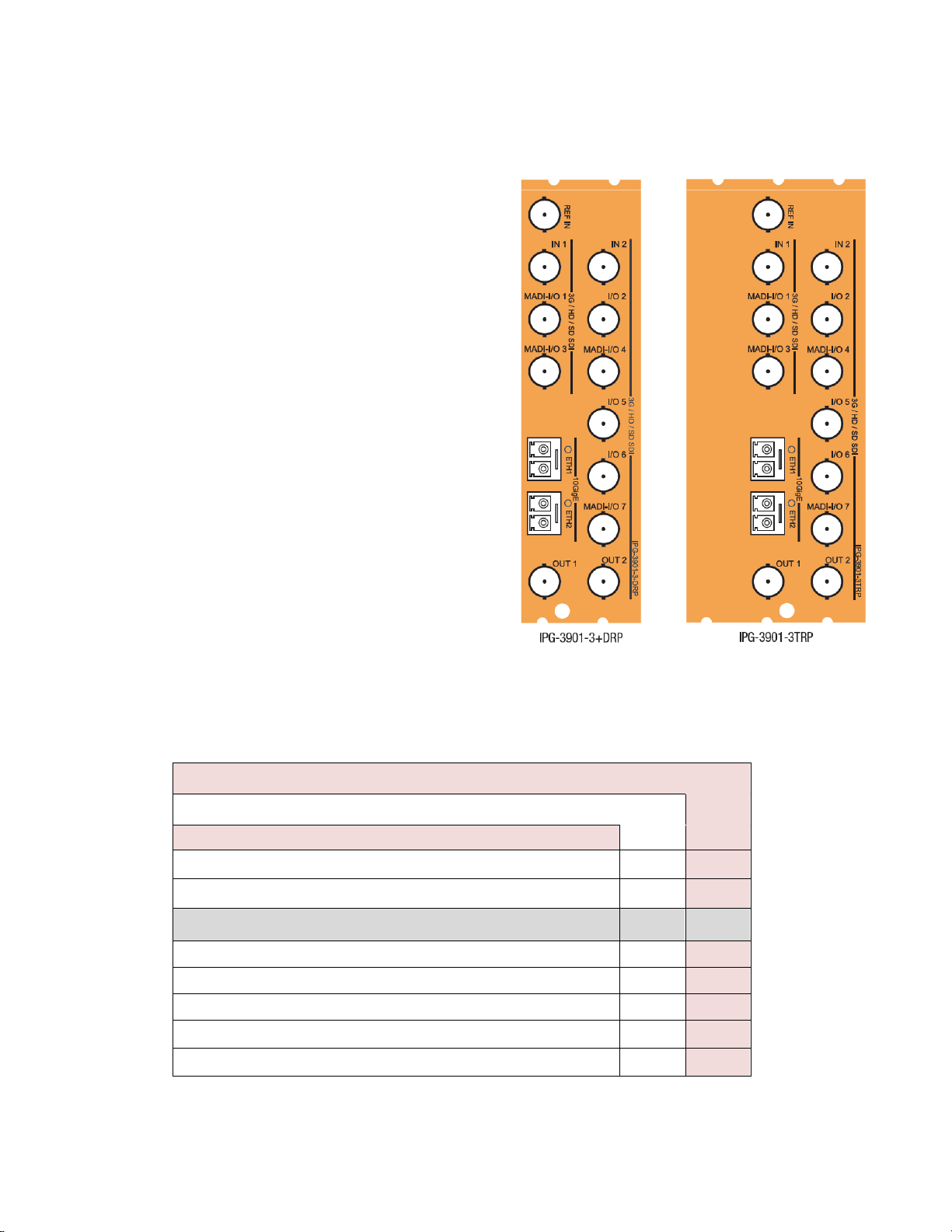
2.3.1 Images of Rear Panel Connectors......................................................................................... 4
2.3.2 Summary of rear panel connections...................................................................................... 4
2.3.3 Details of rear panel connections .......................................................................................... 5
3User Interface...........................................................................................................................6
3.1 Control options.................................................................................................................................... 6
3.2 Card-Edge Status LED ....................................................................................................................... 6
4Local control using the Densité 3 frame control panel .........................................................7
4.1 Overview............................................................................................................................................. 7
4.2 Menu for local control.......................................................................................................................... 7
5Remote control using iControl................................................................................................8
5.1 The iControl graphic interface window................................................................................................ 8
5.2 Gateway Config panel....................................................................................................................... 11
5.2.1 Gateway Config panel – System tab ................................................................................... 11
5.2.2 Gateway Config panel – Gateways tab ............................................................................... 12
5.2.3 Gateways Config panel – Names tab .................................................................................. 14
5.3 Network panel................................................................................................................................... 15
5.3.1 Network panel – Settings tab............................................................................................... 15
5.3.2 Network panel – Status tab.................................................................................................. 15
5.3.3 Network panel – Statistics tab.............................................................................................. 16
5.4 Gateway Status panel....................................................................................................................... 16
5.5 Test panel ......................................................................................................................................... 17
5.6 Factory/Presets Panel....................................................................................................................... 18
5.6.1 Factory................................................................................................................................. 18
5.6.2 Profiles ................................................................................................................................. 19
5.7 Alarm Config Panel........................................................................................................................... 21
5.8 Info Panel.......................................................................................................................................... 24
5.8.1 Info Panel – Info tab............................................................................................................. 24
5.8.2 Info Panel – Technical Support tab...................................................................................... 25
6Specifications.........................................................................................................................26
7Contact Us..............................................................................................................................27
Grass Valley Technical Support................................................................................................................. 27
Corporate Head Office............................................................................................................................... 27
ANNEX – Local Menu...................................................................................................................28

GUIDE TO INSTALLATION AND OPERATION
IPG-3901

GUIDE TO INSTALLATION AND OPERATION
IPG-3901 | 1
1 IPG-3901 High Density SDI/IP Gateway for Densité 3 Platform
1.1 Introduction
The Densité IP Gateway (IPG-3901) plug-and-play modules seamlessly bridge hybrid SDI/IP production
environments. As broadcasters migrate to IP-based transport, these space-saving, low-power cards are easily added
to existing Densité signal processing platforms, converting real-time, uncompressed, baseband video using SMPTE
2022-6 protocol for distribution over 10 GigE networks, and vice versa.
The gateways support any mix of 3G/HD/SD-SDI production workflows over IP networks. With bidirectional I/O in
combinations of 5 in/6 out or 6 in/5 out, the cards offer full redundancy in either unicast or multicast workflows to
ensure uninterrupted service.
Based on the proven Densité modular framework of over 100 functional cards, the flexible, space-efficient IPG-3901
cards accommodate a gradual adoption of IP production elements into broadcasting workflows, while protecting
operational methods and investment in installed equipment. With flexibility to configure up to 6 IPG-3901 modules per
Densité 3 frame and with each IPG-3901 module carrying 11 HD or 6 3G gateways, the Densité 3 platform scales to a
density of 66 HD or 36 3G gateways in a 3 RU frame. In the new Densité 3+ FR4 frame, up to12 IPG-3901 modules
can be installed giving a density of 132 HD or 72 3G gateways in a 4 RU frame. This means space- and cost-efficient
scaling – today and tomorrow.
The Densité IP Gateway can be controlled by the advanced GV Convergent SDN platform, offering unified control
across COTS IP switches and SDI routing/processing infrastructures, as well as by the proven iControl systems.
1.2 Features
•High density configuration with 11 gateways per card – 66 gateways per 3 RU Densité 3 frame or 132 gateways
per 4 RU frame in the new Densité 3+ FR4
•De-encapsulate full bandwidth uncompressed SMPTE 2022-6 to SDI
•Encapsulate SDI into full bandwidth uncompressed SMPTE 2022-6 IP
•Bidirectional transport of SD/HD/3G-SDI video signals over 10 GigE link
•Full 1+1 stream redundancy with automatic change-over link to avoid service interruption
•Bidirectional I/O for 5/6 inputs and 5/6 outputs for up to 11 streams
•Compatible with Densité 3 platform (3 slots in Densité 3 or 2 slots in Densité 3+ frames)
•Integrates with iControl and GV Convergent SDN control frameworks
•IGMPv3 support for IP inputs
•Supports unicast and multicast signals
•Features dual-network interfaces supporting 10 GigE SFP+:
oShort range multi-mode optical
oLong range single-mode optical

GUIDE TO INSTALLATION AND OPERATION
2| IPG-3901
1.3 Functional Block Diagram
Figure 1-1 IPG-3901 Functional Block Diagram
1.4 Front Card-edge Interface
The front card-edge of the IPG-3901 incorporates
two elements:
•Status LED (see section 3.2)
•Select Button (see section 4)
Figure 1-2 Front card-edge layout
Select Button
IRD-3802
Status LED
Status
Select
IPG-3901

GUIDE TO INSTALLATION AND OPERATION
IPG-3901 | 3
2 Installation
2.1 Installation of Rear Connector Panels
Grass Valley Densité-series cards are each associated with a rear connector panel, which must be installed in the
Densité frame before the card can be inserted.
The IPG-3901 card is designed to fit into Grass Valley’s Densité-3 and Densité 3+ frames. Two different rear
connector panels are available:
•IPG-3901-3TRP Triple-slot-width panel for Densité-3
•IPG-3901-3+DRP Double-slot-width panel for Densité-3+FR1 and FR4
See section 2.3 for details of the signal connections available on these panels.
All cards and rear panels can be installed with the frame power on. The card has connectors that plug into a mid-
frame mother board for distribution of power and for connection to the controller card, and a second connector that
plugs directly into the rear connector panel for input and output.
The rear connector panel must be installed with the card out of the frame.
•To remove an existing card from the slot, tilt the swivel handle on the front of the card to lever the
connectors apart, then use the handle to pull the card straight out of the slot.
To install the connector panel:
1. If a card is installed in the slot whose rear panel is being changed, remove it as described above.
2. Remove the existing panel (either blank or belonging to an existing card that is being changed) by releasing the
captive screw(s) at the bottom (Densité 3 or Densité 3+ FR4) or side (Densité 3+ FR1) of the panel.
3. Position the new panel and secure it in place with the captive screw(s) at the bottom or side.
2.2 IPG-3901 Card Installation
Once a matching rear connector panel is in place, install the IPG-3901 card as follows:
1. Open the front panel of the frame.
2. Slide the IPG-3901 card into the slot and push gently on the handle to seat the connectors.
•When using a triple-slot-width rear panel in a Densité-3 frame, the card should be inserted into the right-
most of the three slots.
•When using a double-slot-width rear panel in a Densité-3+ FR1 frame, the card should be inserted into the
lower of the two slots.
•When using a double-slot-width rear panel in a Densité-3+ FR4 frame, the card should be inserted into the
right-most of the two slots.
Inserting the card into the wrong slot will not damage the card, and will be flagged by the on-card status LED
flashing red to indicate that there is no connection to the rear panel.
3. Close the front door of the frame.

GUIDE TO INSTALLATION AND OPERATION
4| IPG-3901
2.3 Rear Panels and Connectors
2.3.1 Images of Rear Panel Connectors
The two available rear panels are shown in the figure. Details of
the inputs and outputs are described below.
NB – references to MADI on the labels for I/O 1, 3, 4 and 7 are
for future use.
2.3.2 Summary of rear panel connections
IPG-3901-3TRP
IPG-3901-3+DRP
Double-slot-width panel for Densité 3+ FR1 and FR4 frames
♦
Triple-slot-width panel for Densité 3 frame
♦
CONNECTORS
Reference IN (future)
1
1
3G/HD/SD SDI IN
2
2
3G/HD/SD SDI OUT
2
2
3G/HD/SD SDI I/O configurable 7 7
10 GigE Ethernet on fiber (SFP+) 2 2
.
Figure 2-1 IPG-3901 Rear Panels

GUIDE TO INSTALLATION AND OPERATION
IPG-3901 | 5
2.3.3 Details of rear panel connections
REF IN – External reference (to be supported in a future release)
Connect an NTSC or PAL reference signal (SMPTE 170M/SMPTE 318M/ITU 624-4 black burst)
3G/HD/SD IN – Serial digital 3G/HD/SD inputs
Connect serial digital video signals, conforming to the SMPTE 425M standard for 3G input signals, SMPTE 292M
standard for HD input signals or SMPTE 259M standard for SD input signals, to the connectors labeled 3G/HD/SD IN
1 and IN 2.
3G/HD/SD OUT – Serial digital video outputs
The IPG-3901 provides two 3G/HD/SD SDI video outputs on the connectors labeled 3G/HD/SD OUT 1 and 2. The
SDI video signal conforms to the input standard. The same signal is carried on both outputs.
3G/HD/SD SDI I/O – Serial digital 3G/HD/SD input or output (configurable)
Seven configurable I/O are provided. The SDI signal requirements are the same as those for the dedicated inputs and
outputs as described above.
10 GbE ETH – 10 GigE Ethernet on fiber (SFP+ Interfaces)
Two 10 Gb Ethernet interfaces (each with Tx and Rx) on optical fiber or twinax cable. SFP+ modules and matching
fiber or electrical connectors are required for the interface.

GUIDE TO INSTALLATION AND OPERATION
6| IPG-3901
3 User Interface
3.1 Control options
The IPG-3901 can be controlled in two different ways:
•The local control panel and its push-buttons can be used to move through a menu of status reports (see section
4).
•Grass Valley’s iControl system can be used to access the card’s operating parameters from a remote computer,
using a convenient graphical user interface (GUI) (see section 5).
3.2 Card-Edge Status LED
The status monitor LED is located on the front card-edge of the IPG-3901, and is visible through the front access door
of the DENSITÉ 3 frame. This multi-color LED indicates the status of the IPG-3901 by color, and by flashing/steady
illumination.
The chart shows how the various error conditions that can be flagged on the IPG-3901 affect the LED status.
•If a cell is gray, the error condition cannot cause the LED to assume that status
•If more than one LED status is possible for a particular error condition, the status is configurable.
See Alarm Config Panel for details.
•The factory default status, if available, is shown by a
The LED will always show the most
severe detected error status that it is
configured to display, and in the chart
error severity increases from left to
right, with green representing no
error/disabled, and flashing red the
most severe error.
If the LED is Flashing Yellow, it
means that the card is selected for
local control using the Densité 3
frame’s control panel. See section 4
for details.
Error Condition
LED Status
Green Yellow Red
Flashing
Red
Hardware failure – cooling fans
Wrong or missing Rear
Ethernet Port 1 Link Status
Ethernet Port 2 Link Status
Internal test pattern enabled
Overall Gateway Status

GUIDE TO INSTALLATION AND OPERATION
IPG-3901 | 7
4 Local control using the Densité 3 frame control panel
4.1 Overview
Push the SELECT button on the IPG-3901 card edge
(see section 1.4) to assign the local control panel to
operate the IPG-3901. Use the control panel buttons to
navigate through the menu, as described below.
All of the cards installed in a Densité frame are
connected to the frame’s controller card, which
handles all interaction between the cards and the
outside world. There are no operating controls located
on the cards themselves. The controller supports
remote operation via its Ethernet ports, and local
operation using its integrated control panel.
The local control panel is fastened to the front of the
CPU-ETH2 controller card, and when installed is
located in the front center of the frame, positioned in front of the power supplies. The panel consists of a display unit
capable of displaying two lines of text, each 16 characters in length, and five pushbuttons.
The panel is assigned to operate any card in the frame by pushing the SELECT button on the front edge of that card.
•Pushing the CONTROLLER button on the control panel selects the Controller card itself.
•The STATUS LED on the selected card flashes yellow.
The local control panel displays a menu that can be navigated using the four pushbuttons located beside the display.
The functionality of the pushbuttons is as follows:
[+] [–] Used for menu navigation and value modification
[SELECT] Gives access to the next menu level. When a parameter value is shown, pushing this button once
enables modification of the value using the [+] and [–] buttons; a second push confirms the new value
[ESC] Cancels the effect of parameter value changes that have not been confirmed; pushing [ESC] causes the
parameter to revert to its former value.
Pushing [ESC] moves the user back up to the previous menu level. At the main menu, [ESC] does not
exit the menu system. To exit, re-push the [SELECT] button for the card being controlled.
If no controls are operated for 30 seconds, the controller reverts to its normal standby status, and the selected card’s
STATUS LED reverts to its normal operating mode.
4.2 Menu for local control
The IPG-3901 has operating parameters that may be adjusted locally at the controller card interface.
•Press the SELECT button on the IPG-3901 front card edge to assign the Densité frame’s local control panel
to the IPG-3901
•Use the keys on the local control panel to step through the displayed menu to configure and adjust the IPG-
3901
•See the ANNEX - Local Menu for a complete menu listing.
Figure
4-1 Densité Frame local control panel

GUIDE TO INSTALLATION AND OPERATION
8| IPG-3901
5 Remote control using iControl
The operation of the IPG-3901 may be controlled using Miranda’s iControl system.
•This manual describes the control panels associated with the IPG-3901 and their use.
•Please consult the iControl User’s Guide for information about setting up and operating iControl.
In iControl Navigator or iControl Websites, double-click on the IPG-3901 icon to open the control panel.
5.1 The iControl graphic interface window
The basic window structure for the IPG-3901 is shown in figure 5.1. The window identification line gives the card type
(IPG-3901) and the slot number where the card is installed in its Densité frame.
There are four main sections in the window itself, as identified in the figure:
Section 1. The top section displays seven icons on the left. These icons report different statuses such as card
communication status, gateway status, health status, and card operation mode.
Icon # 1 2 3 4 5 6 7
Move the mouse over an icon and a status message appears below the icon providing additional information.
If there is an error, the error status message appears in the message area without mouse-over.
•If there are multiple errors, the error messages cycle so all can be seen
1
2
3
Figure
5-1 IPG-3901 iControl graphic interface window
4

GUIDE TO INSTALLATION AND OPERATION
IPG-3901 | 9
•The icon whose status or error message is shown is highlighted with a mauve background
The table below describes the various status icons that can appear, and how they are to be interpreted.
•In cases where there is more than one possible interpretation, read the error message in the iControl window to
see which applies.
Table – iControl Status Icon interpretation
Icon #1 – Manual Card Configuration
(green)
Remote card control activated. The iControl interface can be used to operate the card
(yellow)
Local card control active, The card is being controlled using the Densité frame control
panel, as described in section 4. Any changes made using the iControl interface will have
no effect on the card.
Icon #2 – Gateway status
(green)
All gateways are OK
(red)
At least one gateway is down
Icon #3 – SDI Input Status
(green)
All SDI inputs detected and valid
(red)
At least one SDI input is in error
Reference mismatch
Video/TRS error
Icon #4 – ETH1 Status
(green)
IP link up and active
(red)
No link (port down)

GUIDE TO INSTALLATION AND OPERATION
10 | IPG-3901
Icon #5 – ETH2 Status
(green)
IP link up and active
(red)
No link (port down)
(gray)
Ethernet port not used
Icon #6 – Health Monitoring
(green)
Hardware OK
(red)
Hardware Health Monitoring (Hardware fault detected)
FPGA overheating and has been disabled.
If this icon appears flashing red, you need to change the FPGA FAN and/or DSP FAN
Icon #7 – Operation Mode
(green)
Operation mode: process – normal processing of the input signal
(yellow)
Operation mode: Enabled, but no signal to process.
(yellow)
Operation mode: TEST – color bar and audio test tones enabled on at least one gateway.
Section 2. The left portion of the window contains selection buttons for all of the individual panels, which become
highlighted when they are selected. The main window section (3) then displays the selected panel.
Section 3. The main section displays the panel selected in section 2. It may contain multiple tabs to access any
appropriate sub-panels.
Section 4. The lower left corner of the window identifies the Preset currently in use or “Custom” if none is applicable.
Each of the panels accessed from the buttons in Section 2, and shown in Section 3, is described individually in the
following sections.

GUIDE TO INSTALLATION AND OPERATION
IPG-3901 | 11
5.2 Gateway Config panel
5.2.1 Gateway Config panel – System tab
System-wide Scan Rate: Use the pulldown to
select the scan rate for the system.
•Any input not matching this rate will be
considered invalid.
Receiver FIFO Level (Packets):
This setting determines the number of packets
retained in the input buffer (FIFO).
Generally, IP data streams passing through a network with multiple switches will suffer from “packet jitter”, which must
be processed out in a buffer before conversion to a continuous SDI video signal. If the necessary packets have not
been received before conversion, dropouts will appear in the video. The larger the buffer, the more likely all the
necessary packets will have been received, but the buffer adds latency to the processing, which is not desirable.
The object is to achieve error-free video with the lowest buffer size.
Use the slider, or type directly into the data box, to set the buffer size.
Output on Error: Specify the output behavior of the system when an invalid input is detected
Mode Behavior
Kill Turn the output OFF [DEFAULT]
Configurable
color slate Output a signal in the appropriate format, with the picture being a full-screen color as shown in the sample box
beside the pulldown.
The color is configurable:
1. Click on the color sample to open the Color Selection window.
2. In the Color Selection window, use the sliders, or type directly into the data boxes, to select a color.
Component Range Default
Y 1-254 16
Cb 1-254 128
Cr 1-254 128
3. If the selected color is an invalid system color it will be flagged in the Color Selection window and in the
color sample box.
4. Select Default to choose the system default color (Black: 12, 128, 128) and leave the Color Selection
Scan rate
50 Hz
59.94 Hz
Receiver FIFO level
Range: 3 to 32 packets
Default: 4 packets
Figure
5-2 Gateway Config - System

GUIDE TO INSTALLATION AND OPERATION
12 | IPG-3901
window open.
5. Select Apply to accept the selected color and leave the Color Selection window open.
6. Select OK to accept the selected color and close the Color Selection window.
7. Select Cancel to close the Color Selection window without making changes.
5.2.2 Gateway Config panel – Gateways tab
This page shows the current configuration of all 11
gateways on the card, and provides controls to
modify the configuration.
•Enable/Disable a gateway by clicking the
selection checkbox in the leftmost column (“En”)
of the table.
•Select a gateway by clicking anywhere in its
row in the table.
•Edit the configuration of the selected gateway
using the controls at the bottom.
The table in the panel shows the following:
•En. – checkbox showing enable status
•SDI I/O – 1st line: Name of gateway (fixed)
2nd line: Gateway name
(set in Names tab)
•Dir – the arrow shows the direction of signal
flow between SDI and IP through the
gateway.
•Format: The (non-specific) signal format:
(SD, HD, 3G)
The following two entries show two rows each:
Top row – primary stream information
Bottom row – redundant stream information
•Stream Address – The IP address (source or
destination, depending on the direction of
signal flow) of the stream (unicast or
multicast). In this table, the port is shown
appended to the address (IP:port)
•IGMPv3 Source – Useful only when IGMP is
used. In this protocol, the card deals with a switch to subscribe to one or many streams coming from different IP
addresses. When IGMP is used, the field “stream address” is used to talk to a “group” while the “stream
source” indicates the exact source from which we want to receive the stream.
Note that only one gateway at a time can be fed by a “socket” (stream IP address + port).
Figure
5-3 Gateway Config panel – Gateways tab

GUIDE TO INSTALLATION AND OPERATION
IPG-3901 | 13
The status of the IP stream is shown by the background color of the Stream Address column.
Gateway Direction Color Status
IP Stream to SDI Green IP stream is valid
Red Invalid address
No IP stream
Errors in IP stream
Grey Gateway disabled
SDI to IP Stream Green Normal operations
Orange Not a valid multicast or
unicast address
Red SDI input errors
SDI scan rate error
SDI format error
Grey Gateway disabled
The status of the Gateway is shown by the background color of the SDI I/O column:
Color Status
Green Input video is present
Generating a valid output
Red Input video format mismatch
Error
No input
Not generating an output
Gray Gateway is disabled
The edit box allows the following parameters to be set for the selected gateway:
Parameter Values Default value Notes
Direction (Dir.) → (SDI to IP Stream)
← (IP Stream to SDI) → (SDI to IP Stream)
SDI IN 1 and 2 are hard-coded inputs
SDI OUT 1 and 2 hard-coded outputs
Stream Address
0.0.0.0 to 255.255.255.255
0.0.0.0
SDI to IP Stream
0.0.0.0 and 255.255.255.255 are refused (not applied)
IP Stream to SDI
Multicast address are accepted (224.0.0.0 through
239.255.255.255)
Unicast address are accepted
Stream Port (S. Port) 0 to 9999 1000
IGMPv3 Source 0.0.0.0 to 255.255.255.255 0.0.0.0
R. Stream Address 0.0.0.0 to 255.255.255.255 0.0.0.0 SDI to IP Stream
0.0.0.0 and 255.255.255.255 are refused (not applied)

GUIDE TO INSTALLATION AND OPERATION
14 | IPG-3901
IP Stream to SDI
Multicast address are accepted (224.0.0.0 through
239.255.255.255)
Unicast address are accepted
R. Stream Port (S. Port)
0 to 9999
1000
R. IGMPv3 Source
0.0.0.0 to 255.255.255.255
0.0.0.0
Format
SD, HD, 3G
HD
5.2.3 Gateways Config panel – Names tab
The table shows the eleven SDI I/Os, and the user can
edit the name for each in the Gateway Name column.
1. Select the text to be changed
2. Type the new text
3. Apply to accept the revised text, or
Cancel to discard the changes
The Gateway Name is shown as the second text line in
the SDI I/O column in both the Gateway Config –
Gateways panel, and the Gateway Status panel.
Figur
e 5-4 Gateway Config panel – Names tab
Other manuals for GRASS VALLEY IPG-3901
1
Table of contents
Other Belden Gateway manuals