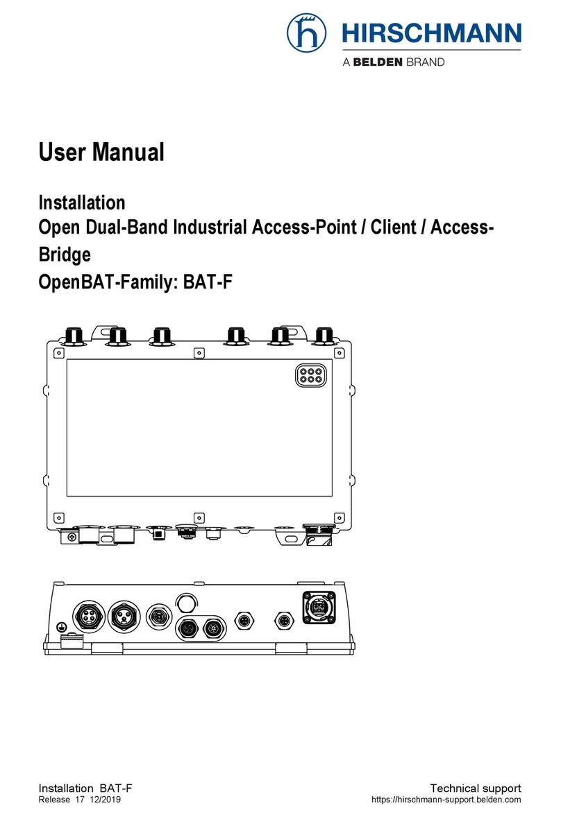
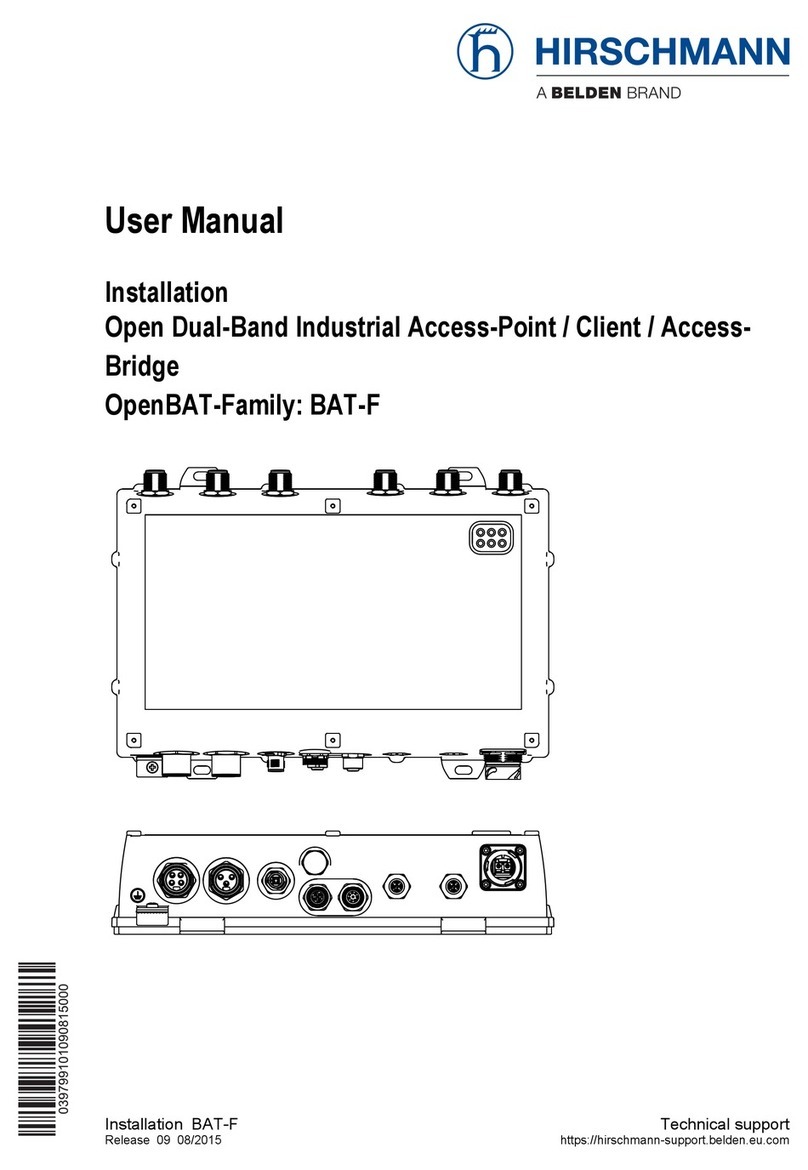
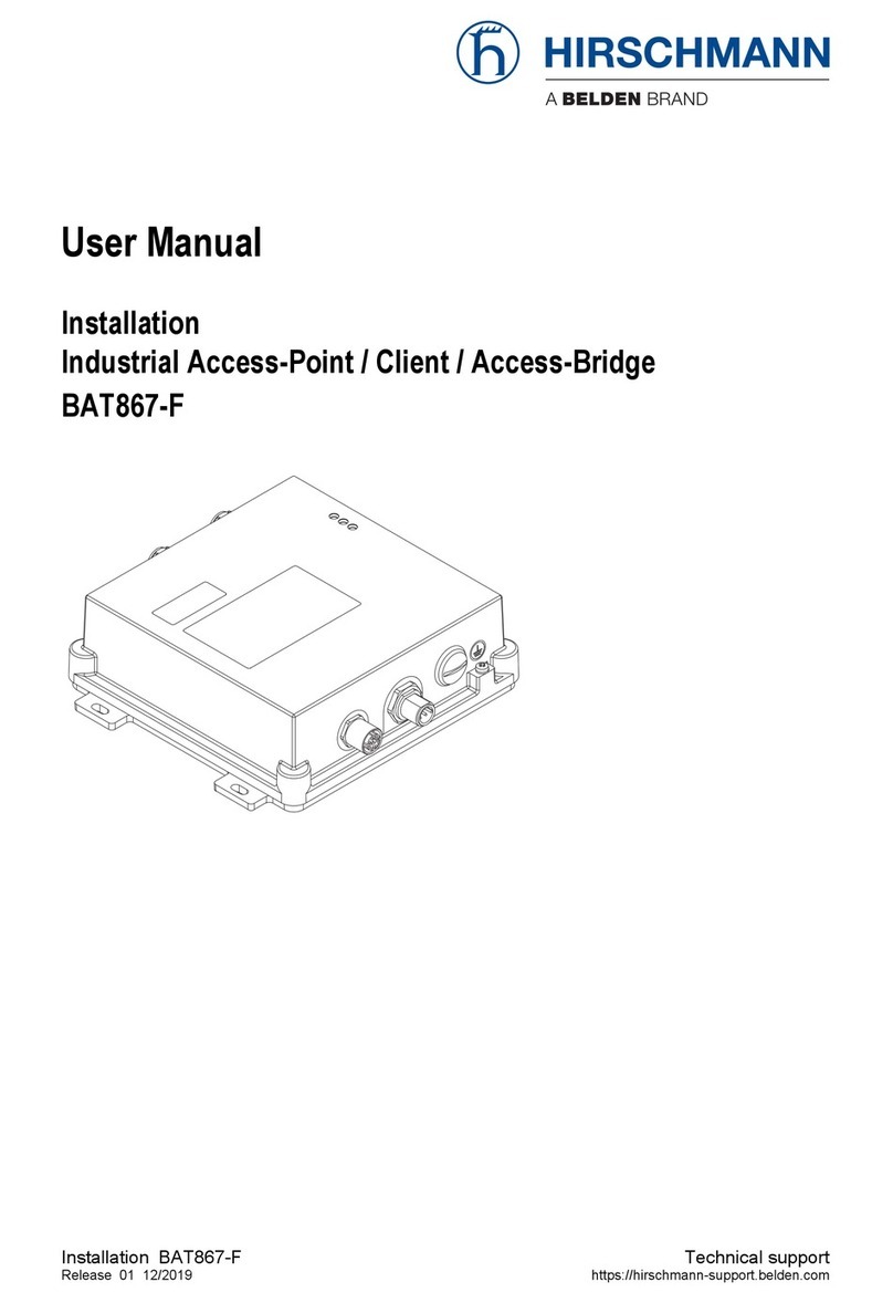
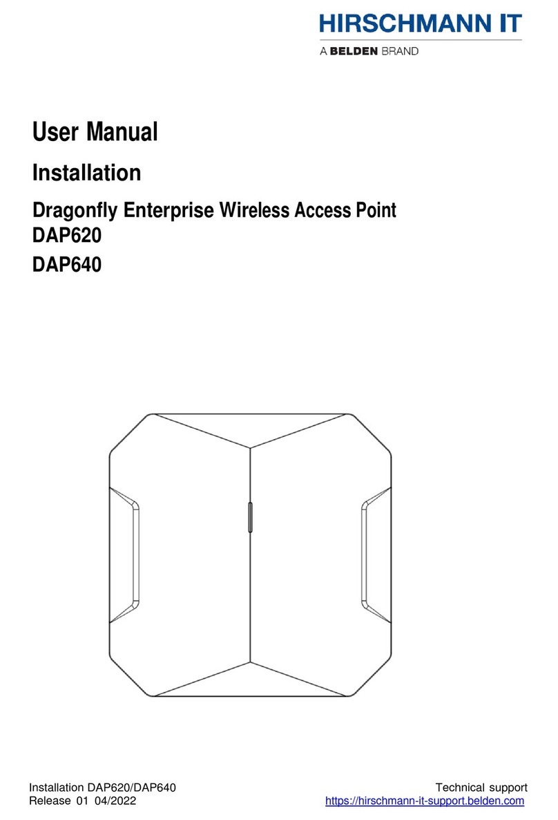
Belden HIRSCHMANN IT Dragonfly Series User manual

Installation DAP645/646/647
Release 01 04/2022
2
Even if not specifically stated, the copyrighted trademark names in this manual shall not be deemed free of
charge in the sense of the trademark and trade name protection act and thus freely available to anyone.
© 2022 Belden Singapore Pte Ltd
Both the manual and software are protected by copyright. All rights reserved. All or any part of this manual shall
be prohibited from being reproduced, copied, translated or converted into any electronic media or machine-
scannable form, except in the case that you make a copy of the software for your own use.
The performance characteristics described herein shall be binding only upon the express consent of the parties
at the time of signing the contract. This paper is produced by Belden within its capacity. Belden reserves the right
to change the contents of this manual without prior notice. Belden does not guarantee the correctness or
accuracy of the information in this manual.
Belden shall not be liable for damages caused by the use of network components or related operating software.
And the conditions of use specified in the license contract are referred to in this manual.
You may access the latest version of this manual at the product website of Hirschmann IT:
https://catalog.belden.com

Installation DAP645/646/647
Release 01 04/2022
3
Contents
Important information.......................................................................5
Safety instructions ............................................................................6
Outdoor installation ............................................................................ 7
Notes for countries with the following country codes: ....................... 10
Supplier's Declaration of Conformity ................................................ 12
U.S. Contact Information.................................................................. 12
About this manual ...........................................................................13
Key …………………………………………………………………………………….13
1Description..............................................................................14
1.1 General device description.............................................................. 14
1.2 Device name and product code ...................................................... 14
1.3 Device view DAP645/ DAP646........................................................ 15
1.4 Device view DAP647 ....................................................................... 16
1.5 Power supply ................................................................................... 17
1.6 Ethernet ports .................................................................................. 17
1.7 Display elements.............................................................................. 18
1.8 Management interfaces.................................................................... 20
2Installation ..............................................................................21
2.1 Checking the package contents ...................................................... 22
2.2 Installing and grounding the device................................................. 22
2.3 Installing the antennas ..................................................................... 42
2.4 Connecting the power supply ........................................................... 43
2.5 Connecting data cables.................................................................... 45
3First login (Password change) ................................................49
4Defining WLAN basic settings ................................................51
5Configuring the transmit power .............................................52
6Maintenance and service .......................................................54

Installation DAP645/646/647
Release 01 04/2022
4
7Disassembly ............................................................................55
8Technical data ........................................................................56
8.1 General technical data ..................................................................... 56
8.2 Dimension drawings......................................................................... 57
8.3 WLAN module specifications ........................................................... 58
8.4 EMC................................................................................................. 60
8.5 Immunity .................................................Error! Bookmark not defined.
8.6 Network range.................................................................................. 61
8.7 Power consumption/power output .................................................... 61
9Scope of delivery ....................................................................62
10 Order number ..........................................................................62
11 Accessories ............................................................................62
12 Underlying technical standards...............................................63
AFurther support.......................................................................64

Installation DAP645/646/647
Release 01 04/2022
5
Important information
Note: Read these instructions carefully and familiarize yourself with the
device before
trying to install, operate, or maintain it. The following notes may
appear throughout this
documentation or onthe device. These notes warn ofpotential hazards or call attention to
information that clarifies or simplifies a procedure.
🞍Symbol explanation
This is a general warning symbol. This symbol alerts you to potential
personal injury hazards. Observe all safety notes thatfollow this symbol
to avoid possible injury or death.
If this symbol is displayed in addition to a safety instruction of the
type
“Danger” or “Warning”, it means that there is a danger of electric shock
and failure to observe the instructions will inevitably result in injury.
This symbol indicates the danger of hot surfaces on the device.In
connection with safety instructions, non-observance of the instructions
will inevitably result in injuries.
WARNING
inevitably result in a serious or fatal accident if not observed.
DANGER
WARNING
indicates a potentially hazardous situation which, if not avoided,
could result in death or serious injury.
CAUTION
NOTE
provides information about procedures that do not involve the risk of injury.
NOTICE

Installation DAP645/646/647
Release 01 04/2022
6
Safety instructions
🞍General safety instructions
You operate this device with electricity. Improper usage of the device entails the
risk of physical injury or significant property damage. The proper and safe
operation of this device depends on proper handling during transportation,
proper storage and installation, and careful operation and maintenance
procedures.
□
Before connecting any cable, read this document, and the safety
instructions and warnings.
□
Operate the device with undamaged components exclusively.
□
The device is free of any service components. In case of a damaged or
malfunctioning device, turn off the supply voltage and return the device to
Hirschmann for inspection.
🞍Certified usage
□
Use the product only for the application cases described in the
Hirschmann IT product information, including this manual.
□
Operate the product only according to the technical specifications.
See “Technical data” on page 56.
□
Connect to the product only components suitable for the requirements of the
specific application case.
Installation site requirements
“Equipment is intended for installation in Restricted Access Area”
Restricted access location:
▶The location is outside the operator access area.
▶The location is accessible to the service personnel even when the
device is switched on.
□
During the installation,make sure that you adhere totheregulationsof
the country in which you are operating the device.
□
In ambient temperatures under -10 °C (+14 °F), use the wiring suitable
for minimum temperatures.
WARNING
UNCONTROLLED MACHINE ACTIONS
To avoid uncontrolled machine actions caused by data loss, configure all data
transmission devices individually.
Before you start any machine, which is controlled via data transmission, ensure to
complete the configuration of all data transmission devices.
Failure to follow this instruction can result in death, serious injury, or
equipment damage.

Installation DAP645/646/647
Release 01 04/2022
7
Outdoor installation
Applies to device with supply voltage (PoE):
▶You connect the device supply via Power over Ethernet (PoE), the circuit
classification ID 1 according to IEC/EN 62368-1, Table 14 applies (max. transient voltage
1500 V, 10/700 µs).
▶The device has been approved for outdoor installation in a pollution degree 2 environment
and according to outdoor enclosure.
▶Observe the mounting instructions in chapter “Installing the antennas”.
Device casing
Only technicians authorized by the manufacturer are permitted to openthe casing.
□
Never insert pointed objects (narrow screwdrivers, wires, etc.) into the
device or into the connection terminals for electric conductors. Do not
touch the connection terminals.
□
At ambient air temperatures > +60 °C (+140 °F):
The surfaces of the device housing may become hot. Avoid touching
the device while it is operating.
🞍Equipment usage
Only instructed or skilled person allowed to use the equipment
(no ordinary person allowed).
🞍Qualification requirements for personnel
□
Only allow qualified personnel to work on the device.
Qualified personnel have the following characteristics:
▶Qualified personnel are properly trained. Training as well as practical
knowledge and experience make up their qualifications. This is the
prerequisite for grounding and labeling circuits, devices, and systems
in accordance with current standards in safety technology.
▶Qualified personnel are aware of the dangers that exist in their work.
▶Qualified personnel are familiar with appropriate measures against these
hazards in order to reduce the risk for themselves and others.
▶Qualified personnel receive training on a regular basis.
🞍National and international safety regulations
□
Verify that the electrical installation meets local or nationally applicable
safety regulations.
Grounding the device
Grounding the device is by means of a separate protective ground connection on the
device.
□
Ground the device before connecting any other cables.
□
Disconnect the grounding only after disconnecting all other cables.
The overall
shield of a connected shielded twisted pair cable is connected to th
e ground
connection on the metal housing as a conductor.
Installation DAP645/646/647
Release 01 04/2022
8
🞍Lightning protection and surge protection
Applies exclusively to devices and antennas installed outdoors:
▶The installation of the device must be carried out by a lightning protection
professional in accordance with valid standards (such as
IEC 62305 / DIN EN 62305 (VDE 0185-305), and in accordance with
the lightning protection procedures recognized and proven for the application
and the environment.
□
Refer to the information in the “WLAN Outdoor Guide” on “Lightning
protection and surge protection”.
The manual is available for download on the Internet:
https://www.doc.hirschmann.com
□
Ensure that the lightning protection professional installs lightning
protection devices (for example lightning conductors) to protect antennas
installed outdoors.
□
Ensure that the lightning protection professional takes appropriate
lightning protection measures that mitigate the effects of lightning strikes.

Installation DAP645/646/647
Release 01 04/2022
9
🞍CE marking
The labeled devices comply with the regulations contained in the following
European directive(s):
2011/65/EU and 2015/863/EU (RoHS)
Directive of the European Parliament and of the Council on the
restrictionof the use of certain hazardous substances in electrical and
electronic equipment.
2014/53/EU (RED)
Directive of the European Parliament and of the council on the
harmonization of the laws of the Member States relating to the making
available on the market of radio equipment.
This product may be operated in all EU (European Union)
countries under the condition that it has been configured correctly.
In accordance with the above-named EU directive(s), the EU
conformitydeclaration will be available to the relevant authorities at the
following address:
Hirschmann Automation and Control GmbH
Stuttgarter Str. 45-51
72654 Neckartenzlingen
Germany
You find the EU conformity declaration as PDF file for downloading on the
Internet at: https://catalog.belden.com
The product can be used in residential areas (residential, commercial
andlight-industrial environments).

Installation DAP645/646/647
Release 01 04/2022
10
Notes for countries with the following country codes:
AT
BE
BG
CH
CY
CZ
DE
DK
EE
EL
ES
FI
FR
HR
HU
IE
IT
LI
LT
LU
LV
MT
NL
NO
PL
PT
RO
RS
SE
SI
SK
TR
▶The RED compliance requires compliant operation of the device in the
5 GHz band channels. Compliant operation of the device is achieved
by an unchangeable determination of the country setting. To obtain
RED compliance, perform the work steps described in chapter
“Obtaining compliance for operation in the European Union and in the
United Kingdom (UK)” on page 11.

Installation DAP645/646/647
Release 01 04/2022
11
🞍UKCA marking
The labeled devices comply with the following UK regulations:
▶S.I. 2012 No. 3032 Restriction of the Use of Certain Hazardous
Substances in Electrical and Electronical Equipment Regulations
▶S.I. 2017 No. 1206 Radio Equipment Regulations
The UKCA conformity declaration will be available to the relevant
authorities at the following address:
Belden UK Ltd.
1 The Technology Centre, Station Road
Framlingham, IP13 9EZ, United Kingdom
You find the UKCA conformity declaration as PDF file for downloading
onthe Internet at: https://www.doc.hirschmann.com/certificates.html
🞍LED or laser components
LED or LASER components according to IEC 60825-1(2014):
CLASS 1 LED PRODUCT

Installation DAP645/646/647
Release 01 04/2022
12
🞍FCC note
Supplier's Declaration of Conformity
47 CFR §2.1077 Compliance Information
DAP645
DAP646
DAP647
U.S. Contact Information
Belden –St. Louis
1 N. Brentwood Blvd. 15th Floor
St. Louis, Missouri 63105, United States
Phone: 314.854.8000
This product has been tested and found to comply with the limits for a
Class A digital device pursuant to Part 15 of the FCC Rules. These
limits are designed to provide reasonable protection against harmful
interference when the equipment is operated in a commercial
environment. This product generates, uses, and can radiate radio
frequency energy and, if not installed and used in accordance with the
manufacturer’s instruction manual, may cause harmful interference with
radio communications. Operation of this product in a residential area is
likely to cause harmful interference, in which case you will be required
to correct the interference at your own expense.
This device complies with Part 15 of the FCC Rules. Operation is
subject to the following two conditions:
(1) This device may not cause harmful interference, and (2) this device
must accept any interference received, including interference that may
cause undesired operation.
FCC Caution: Any changes or modifications not expressly approved by
the party responsible for compliance could void the user's authority to
operate this equipment.

Installation DAP645/646/647
Release 01 04/2022
13
🞍RF exposure warning
This equipment complies with FCC and CE radiation exposure limits set forth for an
uncontrolled environment.
This product may not be collocated or operated in conjunction with any other antenna
or transmitter.
This equipment must be installed and operated in accordance with provided
instructions and the antenna(s) used for this transmitter must be installed to provide a
separation distance of at least 30 cm from all persons and must not be collocated or
operating in conjunction with any other antenna or transmitter.
🞍Recycling note
Afterusage,thisdevicemustbedisposed ofproperlyaselectronicwaste,in
accordance with the current disposal regulations of your county, state,and country.
About this manual
The “Installation” user manual contains a device description, safety
instructions, a description of the display, and the other information that you
need to install the device.
Documentation mentioned in the “User Manual Installation” that is not
supplied with your device as a printout can be found as PDF files for
downloading on the Internet at: https://catalog.belden.com
Key
The symbols used in this manual have the following meanings:
▶Listing
□Work step
🞍Subheading

Installation DAP645/646/647
Release 01 04/2022
14
1Description
1.1 General device description
Hirschmann IT Dragonfly outdoor series is enterprise level Wi-Fi 6(802.11ax) certified access
point including DAP645/646/647.
There are convenient options for managing the device. Manage your devices via:
▶Web browser
▶SSH
▶Telnet
The device works without a fan.
The device complies with the degrees of protection IP67.
1.2 Device name and product code
The device name corresponds to the product code.
Order number
Product code
Description
942999308
DAP645-RW
Outdoor 802.11ax 4*4 MIMO AP, data rate
2.97Gbps, build-in omni-antenna;
Default shipping without mounting kit.
942999312
DAP646-RW
Outdoor 802.11ax 4*4 MIMO AP, data rate
2.97Gbps, build-in directional-antenna;
Default shipping without mounting kit.
942999316
DAP647-RW
Outdoor 802.11ax 4*4 MIMO AP, data rate
2.97Gbps, extended antenna with 6*N-type
female connectors;
Default shipping without mounting kit.
Table 1: Device name and product code

Installation DAP645/646/647
Release 01 04/2022
15
1.3 Device view DAP645/ DAP646
Figure 1: Device view DAP645/ DAP646
1
Reset
Factory reset. Press reset button for 5s, AP LEDs
will quickly flash for 3s, then AP will restart and
restore factory configurations
2
SFP
SFP module need to be purchased additionally
3
Protective vents
Don’t open or remove
4
Grounding point
The grounding must be completed before powering
up the AP
5
Eth0/PD
1×10/100/1000/2500Mbps (RJ-45) port, Eth0,
Power over Ethernet (PoE) 802.3bt/at compliant
6
Eth1/PSE
1×10/100/1000Mbps (RJ-45) port, Eth1, up to
802.3at PSE in case of Eth0 802.3bt Type4 PoE
input
7
Status indicators
For system and radio status

Installation DAP645/646/647
Release 01 04/2022
16
1.4 Device view DAP647
Figure 2: Device view DAP647
1
Reset
Factory reset. Press reset button for 5s, AP LEDs
will quickly flash for 3s, then AP will restart and
restore factory configurations
2
SFP
SFP module need to be purchased additionally
3
Protective vents
Don’t open or remove
4
Grounding point
The grounding must be completed before powering
up the AP
5
Eth0/PD
1×10/100/1000/2500Mbps (RJ-45) port, Eth0,
Power over Ethernet (PoE) 802.3bt/at compliant
6
Eth1/PSE
1×10/100/1000Mbps (RJ-45) port, Eth1, up to
802.3at PSE in case of Eth0 802.3bt Type4 PoE
input
7
Status indicators
For system and radio status
8
Antenna terminal
6x external Type-N connectors, labeled ANT0,
ANT1, ANT2, ANT3, ANT4, and ANT5

Installation DAP645/646/647
Release 01 04/2022
17
1.5 Power supply
You have the following options to supply your device with voltage:
1.5.1
Supply voltage with PoE
🞍Power supply via RJ45 socket for PoE port
Your device support PD (powered device) and PSE (power sourcing equipment).
Connect the device via a twisted pair cable on the PD port as power supply input,
and on the PSE port as power supply output. The PoE power supply means that no
separate power supply is required for your device.
1.6 Ethernet ports
You have the option to connect end devices or other segments to the ports
of the device via twisted pair cables.
You find information on the pin assignments for making patch cables here:
See “Pin assignments” on page 18.
1.6.1
10/100/1000 Mbit/s PSE port
This port is a RJ45 socket.
This port supports:
▶Autocrossing (if autonegotiation is activated)
▶Autonegotiation
▶Autopolarity
▶10 Mbit/s half-duplex mode, 10 Mbit/s full duplex mode
▶100 Mbit/s half-duplex mode, 100 Mbit/s full duplex mode
▶1000 Mbit/s full duplex
▶Power over Ethernet
The socket housing is electrically connected with the device housing.
Delivery state: Autonegotiation activated
1.6.2
1Gbit/s F/O port
This port is a SFP slot.
The port allows you to connect network components according to IEEE 802.3.
This port supports:
▶Full duplex
▶Delivery status
▶1 Gbit/s full duplex when 1 Gbit Ethernet SFP transceiver is used.
1.6.3
10/100/1000/2500 Mbit/s PD port
This port is a RJ45 socket.
This port supports:
▶Autocrossing (if autonegotiation is activated)

Installation DAP645/646/647
Release 01 04/2022
18
▶Autonegotiation
▶Autopolarity
▶10 Mbit/s half-duplex mode, 10 Mbit/s full duplex mode
▶100 Mbit/s half-duplex mode, 100 Mbit/s full duplex mode
▶1000 Mbit/s full duplex
▶2500 Mbit/s full duplex
▶Power over Ethernet
The socket housing is electrically connected with the device housing.
Delivery state: Autonegotiation activated
The PoE power is supplied via the wire pairs transmitting the signal (phantom
voltage).
1.6.4
Pin assignments
1.7 Display elements
After the supply voltage is set up, the Software starts and initializes the device.
Afterwards, the device performs a self-test. During this process,various LEDs light
up.
1.7.1
LED Indicators
LED Indicator for DAP645/ DAP646/ DAP647

Installation DAP645/646/647
Release 01 04/2022
19
Lights
Activity
Meaning
PSE
ON
PSE enabled
SFP
ON
SFP linkup
Eth1
ON
Ethernet1 linkup
Eth0
ON
Ethernet0 linkup
5G
ON
5GHz SSID created and running
2.4G
ON
2.4GHz SSID created and running
SYS
ON
Bootloader-OS loading and system running
Flashing
Bootloader-OS upgrading

Installation DAP645/646/647
Release 01 04/2022
20
1.8 Management interfaces
1.8.1
Reset button
The device has a reset button. The reset button is located behind a screwable IP67
protection cap.
Press reset button for 5s, LED will quickly flash for 3s, then the device will restart and
restore factory configurations
Prerequisite: Keep the working area dry and clean when you are carrying out a reset.
After pressing the reset button, replace the protection cap. Degrees of protection IP67 are
only achieved when the protection cap is closed.
This manual suits for next models
4
Table of contents
Other Belden Wireless Access Point manuals

Belden
Belden Hirschmann BAT867-F User manual

Belden
Belden Hirschmann BAT-F Series User manual

Belden
Belden HIRSCHMANN IT Dragonfly DAP620 User manual

Belden
Belden Hirschmann OpenBAT BAT-R User manual

Belden
Belden Hirschmann BAT867-R User manual

Belden
Belden HIRSCHMANN BAT450-F User manual

Belden
Belden Hirschmann BAT-F User manual
Popular Wireless Access Point manuals by other brands

Honeywell
Honeywell Field Device Access Point user guide

LevelOne
LevelOne WAB-3003 Specifications

Alfa Network
Alfa Network AWAP02O-86 Specifications

Tonze
Tonze aw 6660 Quick installation guide

Quantum
Quantum QN-H-245 Quick setup guide

MikroTik
MikroTik RouterBOARD Groove 5Hn Quick setup guide and warranty information