BelFox 47-21-i User manual


2

3
1.) Control elements of the board
1 a) Display
The control board 47-21-i is equipped with a standard illuminated display for easy
programming and trouble shooting.
1 b) Buttons
4 buttons are installed on the control for easy menu access and control.
Button Status panel Menu
↑+ Start / Stop opening Menu item / value + 1
↓- Start / Stop closing Menu item / value –1
/ Return Impulse (opening–stop –closing –
stop… ) Confirmation of the menu item /
application
Escape /
Menu Return to the menu items Return to a menu item without
memorizing of the modifications
4
2.) Wire connections
2 a) Plan for wire connections
Removeble terminal blocks (SL1 –SL8) for easy external wire connection have been
placed on the board. This system enables easy replacement of the controller board if
necessary.
DANGER !
Prior to connecting, all terminal blocks must be voltage free!
Danger! Terminals 1 to 8 are connected to 230 volts!
Do not apply any main voltage to the terminals 9 to 36!
The improper use/operation could damage the control board and the guarantee claim
would become invalid.
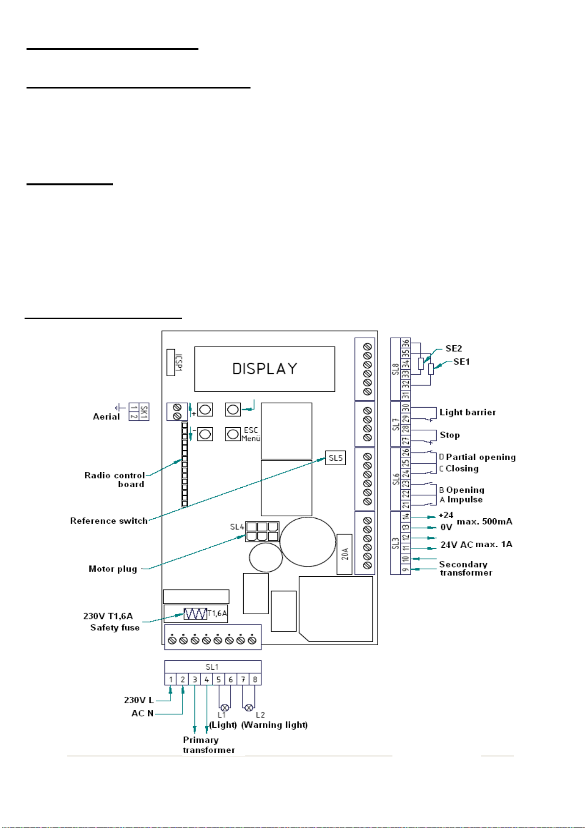
2 b) Connection plan

5
2 c) Terminal blocks [Detailed connections]
Connector block 1 (SL1) –High voltage terminal
Terminal 1 & 2: Connection of the 230V/ 50Hz power supply (1-L / 2-N)
connected in the factory.
Terminal 3 & 4: Connection of the 230V / 50Hz primary side of the transformer
(3-N / 4-L) connected in the factory.
Terminal 5 & 6 Connection of the 230V / 50Hz lighting (5-N / 6-L)
Terminal 7 & 8: Connection of the 230V / 50Hz lighting „warning light“
(7-N / 8-L)
Connector block 3 (SL3) –Low voltage supply for external devices
Terminal 9 & 10: Connection of the 24V / 50Hz Secondary side of the transformer
(Input) (already connected in the factory.)
Optional connection of the 24V DC voltage
Terminal 11 & 12: Direcly connected to terminals 9 & 10
(Output) Output of the power supply 24V- AC voltage (Standard power
supply of the control board through terminal 9 & 10 with AC
voltage / transformator)
Output current 24V- DC voltage
(By battery mode [DC-USV-power supply] of the control board
through terminal 9 & 10)
Terminal 13 & 14: Output current 24V- DC voltage
(Output) max.500mA (13 = Gnd. mass / 14 = +24V)
Connector block 5 (SL5) –Reference switch (for potential -free opening reed
contacts)
The reference switch has already been tailored and has been plugged into terminal SL5
Connector block 6 (SL6) –Push-button inputs (for potential-free closing
contacts)
Terminal 21: Button input A: Impulse function (commun terminal 22)
Terminal 22: Common terminal of the button inputs A & B
Terminal 23: Button input B: targeted opening function (commun terminal 22)
Terminal 24: Button input C: targeted closing function (commun terminal 25)
Terminal 25: common terminal of the button inputs C & D
Terminal 26: Button input D –partial opening function (commun terminal 25)

6
Connector block 7 (SL7) –Safety input Stop & light barrier
(for potential-free opening contacts, see 2e & 2f)
Terminal 27 & 28: Stop input –Wicket door safety input
Terminal 29 & 30: Connection of the safety light barrier (for the opening contact of
the light barrier)
Connector block 8 (SL8) –Safety inputs for 8,2kΩ safety contact edges or OES-
edges (see 2g & 2h)
By usage of 8,2kΩ safety contact edges:
Terminal 31: not used
Terminal 32 & 35: SE1 –Safety input 1
(Connection of the 8,2kΩ safety contact edges- activated during
closing)
Terminal 33 & 36: SE2 –Safety input 2
(Connection of the 8,2kΩ safety contact edge - activated during
opening)
Terminal 34: not used
By usage of OES-safety contact edges (optoelectronical safety contact edges)
Terminal 31: OES + 12V max. 150mA
Terminal 32: OES 1 optoelectronical safety contact edge 1
Terminal 33: OES 2 optoelectronical safety contact edge 2
Terminal 34: OES –0 volt mass
Terminal 35 & 36: not used
2 d) Connection of the aerial / radio board
A wire aerial is connected to the lower terminal of the SK1 (Terminal 2).
The length of the wire aerial depends on the frequency and should hang to the side of
the control board.
As an alternative to wire aerial, the cable core of a rod aerial can be connected to
terminal 2. We recommend mounting the aerial rod as high as possible in order to
avoid frequency disruptions caused by the gate.
The receiving frequency depends on the 15-pin radio plate. The recievieng frequency
of 868, 3 MHz is currently included as standard equipment. Optionnaly, it is possible
to order other frequencies such as 433, 92 MHz, 40,685 MHz and 27,015 MHz.

7
2 e) Light barrier
Power supply:
The supply voltage can be tapped from the control board.
Terminal 1+2 =230 AC (mains voltage)
Terminal 11+12 =24V AC (Alternative current – in use of power supply with
transformer)
Terminal 13+14 =24V DC (Direct current)
The potential-free opening contact (closed when inactive) of a light barrier can be
connected to the terminals 29 & 30. Furthermore, it is possible to connect several
safety contact edges. Their potential-free opening contacts must be connected in
series.
Is the operating mode AUTOMATIC CLOSING activated, the gate will close
optionally after the deactivation of the input “closing after leaving the light barrier
with set delay”or “after expiration of the hold-open time”.
External safety devices must be approved for personal safety since their function is
not tested by the control board! The reliability of their performance must be tested at
least every 6 months.
2 f) Stop input / Wicket door
The potential-free opening contact (closed when inactive) of a wicket door and/or of
an emergency stop control can be connected to the terminals 27 & 28.
Furthermore, it is possible to connect several safety devices. Their potential-free
opening contacts must be connected in series.
This safety input is activated in both directions of the gate. When this input is
activated the drive of the gate will not operate or a moving gate will come to an
emergeny stop. CAUTION: In this case no reversing will be operated and disable is
activated.
2 g) 8,2kΩ-safety contact edges
It is possible to connect safety contact edges with an 8,2kΩ terminating resistor
between the terminals 32 & 35 and between 33 & 36.
SE1 (closing) (Safety input 1 –terminals 32 & 35)
SE2 (closing) (Safety input 2 –terminals 33 & 36)
External safety devices must be approved for personal safety since their function is
not tested by the control board! The reliability of their performance must be tested at
least every 6 months.
8
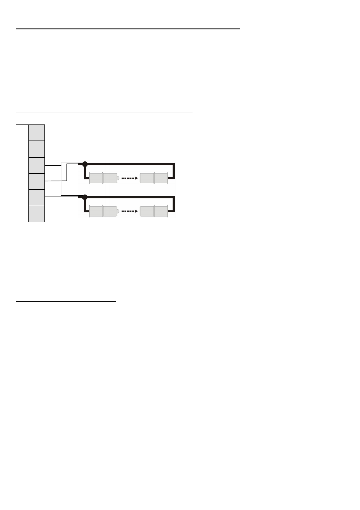
2 h) Optoelectronical safety contact edges (OES)
It is possible to connect optoelectrical safety contact edges between the terminals 31
and 34.
The power supply of the OES DC 12V has to be connected to the terminal 34=mass
and to 31=+12V max. 150mA.
The OSE1 has to be connected to the terminal 32 and the OSE2 to the terminal 33.
Connection of two OES-safety contact edges:
3
6
3
5
3
4
3
3
3
2
SL 8
3
1
External safety devices must be approved for personal safety since their function is
not tested by the control board! The reliability of their performance must be tested at
least every 6 months.
2 i) Battery operation
It is possible to supply the control board with a 24V battery.
The power supply of the battery has to be connected to the terminals 9 & 10
(The polarity does not have to be taken into account).
ATTENTION: If a battery is connected to the terminals 9 & 10, the transformer
should not be connected!
ATTENTION: The dimensions and the weight of the gate are limited if the gate
drive is battery operated!
max. dimensions of the gate: 6m
max. weight of the gate: 350kg
.
.
OS
E
-
closing
OS
E
-
opening
brown +
white
-
green
1
green
2

9
3.) Programming
3 a) General programming
Use the 4 buttons positioned on the control board in order to programm the
controller. (see 1b).
Use the buttons „top left“and „down left“with the symbols „↑+“ and „↓-“in order to
select and confirm your choices in the menu items.
Use the buttons „down right“with the inscription „Escape/Menu“in order to select
one of the 6 main menu items and to quit them without saving the modifications.
Main menu item Explanation
„Status panel“ Display of the current status of the motor (opening /
closing / idle mode / advance warning)
Display of the active inputs
Menu Configuration of functions (menu items 1-26)
Memorizing runs Teaching in/deletaing of end-of-travel positions and forces
Radio level Teaching in/delating of hand transmitters
malfunc Display of the last 10 malfunctionnings
Last orders Display of the last 50 commands
Use the button „up right“with the sign „ / Return“in order to confirm your
choices.

10
3 b) Configuration of software functions
Caution: Every time the parameters are changed the memorized runs must be learnt
again!
Press „Escape/Menu“until, „Menu“appears in the display. Enter with the button
„ / Return“.
Use the buttons „↑+“ and „↓-“-“in order to select the desired functions/options,
which will be described in the following sections. Confirm with the button „ /
Return“.
To change the parameters push the button „↑+“ or „↓-“. When the desired parameter
has been reached, confirm with „ / Return“.
In the following menu items you will find more information.
Wenn you reached the next menu item, all the modifications performed in the
previous one have been saved.
You can quit the menu
WITHOUT
memorizing the modifications by pressing several
times the button „Escape/Menu“, until you return to the previously selected menu
item.

11
General view / Information concerning the menu items:
1. Language: The following languages are available: 1. Deutsch
2. English
3. Français
4. Niederländisch
2. Type of gate: Preprogrammed configurations for following portal types are available:
0: Sliding g. lft (Sliding gate with DIN LEFT)
1: Sl. G. l. 8k2 (Sliding gate with DIN LEFT and 8,2kΩ safety contact
edges)
2: Sl. l. 8k2 a cl (Sliding gate with DIN LEFT, 8,2kΩ safety contact edges
and automatic closing)
3: Sliding g rgh (Sliding gate with DIN RIGHT)
4: Sl. G. r. 8k2 (Sliding gate with DIN RIGHT and 8,2kΩ safety contact
edges)
5: Sl.r 8k2 a cl (Sliding gate with DIN RIGHT, 8,2kΩ
safety contact edges and automatic closing)
6: garage (Garage door)
7: Garage aut.cl. (Garage door with automatic closing)
8: Gar wing gates (Garage door with pedestrian leaf)
9: Garage wr. ac. (Garage door with pedestrian leaf and automatic closing)
A: Slid.G. lft LS (Sliding gate with DIN LEFT and limit switches)
B: Slid.G. rgh LS (Sliding gate with DIN RIGHT and limit switches)
C: GarageLimitSw (Garage door with limit switches)
D: gar wg.Gate LS (Garage door with pedestrian leaf und limit switches)
To decide if your gate DIN left or DIN right is, please read point 4a.
3. Radio: this menu item allows one to: -Learn radio: learn codes of new hand
transmitters.
-Cancel radio: delete all previously
saved hand transmitter codes.
-Radio level: display strength of signal
from hand transmitters & display of the
active hand transmitter.
-Amount acc.: display of the number of
hand transmitters which have previously
been saved.
-System: display of the actual bit-system
(The bit system of the 1st hand transmitter
will be saved)

12
4. Sensor/ES:
This menu item allows you to set a position indicator
1. Sensor
2. Sens. with ref.
3. Limit switch
In the following part of the menu item Sensor/ES you can see which
Hallsensor, Limit switch or Reference switch are currently activated.
5. → A Impulse: This menu item is for informative purposes only! Here you can see
if input A active (ON) or incative (OFF) is.
6. → B opening: This menu item allows you to set the mode of operation of
the input B:
1: Stop panic (opening… stop… opening … stop… opening … )
2: Stop no panic (opening … a opening … opening … opening … )
3: “death man”(Press-and-hold travel: the gate opens only as the
respective buttons are pressed)
7. → C closing: This menu item allows you to set the mode of operation of
the input C:
1: Stop panic (closing… stop… closing … stop… closing … )
2: Stop no panic (closing … closing … closing … closing … )
3: “death man” (Press-and-
hold travel: the gate closes only as the
corresponding buttons are pressed)
8. → D Partial opening: This menu item allows you to set the mode of operation of
the input D:
1: Stop panic
(Opening=>part.op..… stop… opening => part.op.… stop… )
2: Stop no panic
(Opening => part.op.… opening => part.op.… opening => part.op.… )
Furthermore ist he pourcentage of the partial opening
adjustable here: This value must be under 100%.
Is input D permanently active and the gate closes
automatically from end pos. OPEN, the gate will only close to
the partial opening position.

13
9.
CEL (
Light barrier
)
:
This menu item allows you to program the effect of the
light barrier after it has been activated:
NO function
OP: stop
OP: disengaging (about 1 sec.)
OP: reverse
CL: Stop
CL: disengaging
CL: reverse
10. SE1 (closing): This menu item allows you to set whether the board controls the
Safety input SE1 (terminal 32) in relation to an 8,2kΩ resistance
safety contact edge or an OSE-edge (Optoelectrical safety edge).
1: 8k2
2: OSE
Program the effect of the security device SE1 by closing after it
has been activated:
1: NO function
2: Stop
3: disengaging (about 1 sec.)
4: reverse
11. SE2 (opening): This menu item allows you to set whether the board controls the
Safety input SE2 (terminal 33) in relation to an 8,2kΩ resistance
safety contact edge or an OSE-edge (Optoelectrical safety
edge).
1: 8k2
2: OES
Program the effect of the security device SE2 by opening after it
has been activated:
1: NO function
2: Stop
3: disengaging (about 1 sec.)
4: reverse
12. SE-Standby: This menu item allows you to set whether the board cuts off the
12V power supply of the optoelectrical safety edge (Terminals 31
& 34) at gate standstill in order to save energy.
(This function is only necessary by battery mode): 1: No Standby
2: Standby

14
13. Stop:
This menu item is for informative purposes only!, you can see whether the
stop is open <active> or closed <OK>.
14. Warning light: This menu item allows you to set the time the warning light
goes on before the gate closes or opens (0-10 sec.)
(Terminals 7 & 8).
The warning light is always active when the motor is operating
It can be tested with the buttons <+> und <->.
15. Light: This menu item allows you to adjust the time the light stays on after the
motor stopped operating (Terminals 5 & 6)
.
You can adjust it in seconds (from 0 - 99) and in minutes (from 2 –10)
The light is always on when the motor is operating.
It can be tested with the buttons<+> and <->.
16. Aut. closing: This menu item allows you to adjust the start time of the automatic
closing option. The time until the gate automatically closes can be
set from (0 to 99 seconds) in seconds or (2-10 minutes) in
minutes. Furthermore it also allows you to set the time the gate
atomatically closes after leaving the OES (from 0 to 20 seconds)
17. Current stop OP: This menu item allows you to configurate motor over current
shut down, which is used to detect obstacles, in the opening
direction.
You can: -Modify its status: <active> or <inactive>.
-Configurate the period of inactivity of the emergency shut down.
-Configurate an additional value which will be added to the values that
have already been learnt.
18. Current stop CL: This menu item allows you to configurate the emergency shut
down, which is used to detect obstacles, in the closing
direction.
You can: -Modify its status: <active> or <inactive>.
-Configurate the period of inactivity of the emergency shut down.
-Configurate an additional value which will be added to the values that
have already been learnt.
19. Speed: This menu item allows you to adjust separately the speed of the
movement by the opening and closing of the gate. This is a pourcentage
setting of motor voltage which in return will not be completely linear.
20. Smooth start: This menu item allows you to configurate the speed at the start
and the duration of the smooth start.

15
This function is for the moment unavailable.
We are still working on it
21. Smooth run OP: This menu item allows you to set the speed of the smooth run
in the opening direction. The length of the smooth run can be
adjusted in percent.
CAUTION:
For security reasons, the run out length must be at least 60 cm long!
The length corresponds to the values in percent contained in the table in the next section.
22. Smooth run CL: This menu item allows you to set the speed of the smooth run
in the closing direction. The length of the smooth run can be
adjusted in percent.
CAUTION:
For security reasons, the run out length must be at least 60 cm long!
The length corresponds to the following values in percent:
IS* at the opening in m 1 2 3 4 5 6 7 8 9
Min. length of smooth run 60% 30% 20% 15% 12% 10% 9% 8% 7%
IS* at the opening in m 10 11 12 13 14 15 16 17 >17
Min. length of smooth run 6% 5% 5% 5% 4% 4% 4% 4% 4%
* Intermediate Space
23.Two-way traffic:
24. Cancel data: This menu item allows you to delete the following data:
1: -----
(No deletion)
2: forces
(Deletion of the memorized forces)
3: way + forces
(Deletion of the memorized end-of-travel positions and forces)
4: adjustment
(deletion of all memorized configurations)
25. Cycle counter: This menu item is for informative purposes only!
You can see the total number of cycles. It is impossible to delete this value.
26. Version: This menu item is for informative purposes only!
You can see which software version has been programmed.

16
3 c) Learning runs of systems equipped with a sensor
A
TTENTION
: Light barriers, safety contact edges and other safety equippment must
be deactivated before learning runs or has not to be obstructed during
a normal run.
Press „Escape/Menu“until „Memorizing runs“appears in the display. Enter with
the button „ / Return“.
Keep the button „↑+“ or „↓-“pressed in order to open the gate with the deadman
function. It is possible to interrupt several times the travel of the gate by releasing
the button. As soon as the final open-position has been reached, confirm with the
button „ / Return“.
„Memorizing close ?“ appears on the display. Confirm with the button „ /
Return“.
The control board closes automatically the gate to the travel end-of-position which is
determined by the over current.
It is possible to interrupt the movement of the gate before it reaches the final position
with the buttons „↑+“ or „↓-“and to close it manually with the buttons „↑+“ and
„↓“.
Once the closed end-of-travel position is reached, no matter how (automaticly or
manually), confirm with the button „ / Return“.
„Fin pos open? “appears on the display, confirm with the button „ / Return“.
The control board will now automatically learn the amount of motor current (Amps)
needed to OPEN the gate.
„Fin pos close?”appears on the display, confirm with the button „ / Return“.The
control board will now automatically learn the amount of motor current (Amps)
needed to CLOSE the gate.
Memor runen OK?“appears on the display. If you are satisfied with all lerning
runs, confirm with the button „ / Return“.
If the runs are somehow interrupted, (Safety device, etc.) select with the buttons
„↑+“ and „↓-“the answer →No←, Confirm with the button „ / Return“and
repeat the steps described in this section. (“3c)”).

17
3 d) Learning runs of systems equipped with 2 limit switches
A
TTENTION
: Light barriers, safety contact edges and other safety equippment must
be deactivated before learning runs or has not to be obstructed during
a normal run.
Teaching in
Press „Escape/Menu“, until „Memorizing runs“appears in the display. Enter with
the button Taste „ / Return“.
Press once the button „↑+“. The motor drive stops the opening run when the limit
switch for open has been reached. „Fin pos open”appears on the display. Confirm
with the button „ / Return“.
„Memorizing close ?“ appears on the display. Confirm with the button „ /
Return“. The operator closes automatically the leaf and comes to a standstill after
the limit switch has been reached.
„Fin pos close?“appears on the display. Confirm with the button „ / Return“.
„Memor run open ?“ appears on the display. Confirm with the button „ /
Return“. The leaf opens automatically. It comes to a standstill when it has reached
the limit switch and the motor switches off.
„Fin pos close?”appears on the display. Confirm with the button „ / Return“.
„Fin pos open? “appears on the display. Confirm with the button „ / Return“.
„Memor runen OK?“appears on the display If you are satisfied with all lerning
runs, Confirm with the button „ / Return“.
If the runs are somehow interrupted, (Safety device, etc.) select with the buttons
„↑+“ and „↓-“the answer →NO←, Confirm with the button „ / Return“and
repeat the setting stepps described in the section 3d).

18
3 e) Teaching in of the radio codes
ATTENTION If either of 12-bit and 18-bit systems has been taught in, further
hand transmitters with the same bit systems can be taught in. This allows only hand
transmitters with the same bit system to be learnt. Prior to chaging the system, it is
necessary to delete all the memorized hand transmitters.
Teaching in
Press „Escape/Menu“, until „Radio level“appears in the display. Confirm with the
button „ / Return“.
„Lern radio?“appeares on the display, enter with the button „ / Return“.
Select the desired function with the buttons „↑+“ and „↓-“(see the following list of
functions) and confirm your choice with the button „ / Return“.
Functions: F1: Impulse (opening … stop… closing … stop… opening … stop… )
F2: Opening with stop (opening … stop… opening … stop… )
F3: Closing with stop (closing … stop… closing … stop… closing)
F4: Stop
F5: Partial opening (traffic leaf, see section 8 of menu, -page 12)
F6: Opening without stop (opening… opening … opening … )
F7: Closing without stop (closing… closing … closing … )
F8: Light (turning up of the light)
Press the desired button on the hand transmitter until „Accepted“appears on the 2
nd
line of the display. The button of the hand transmitter has just been lear.
Deletion
It is possible to delete all hand transmistters or only individual hand transmitters.
Press „Escape/Menu“, until „Radio level“appears in the display. Enter with the
button „ / Return“.
Press the buttons „↑+“ and „↓-“to select the function „Cancel radio?“and confirm
with the button „ / Return“.
Select with the buttons „↑+“ and „↓-“ the desired option: „0: All“(all hand
transmitters) or only individual hand transmitters. Confirm your choice with the
button „ / Return“.

19
3 f) Display of malfunctionnings
In order to see the last malfunctionnings, press „Escape/Menu“, until
„Malfunctions“appears in the display. Confirm with the button „ / Return“.
You can see with the buttons „↑+“ and „↓-“the last 10 malfunctions and also how
much time has passed since the malfunctionning has been detected.
Message malfunctionning Correcting faults
------ No malfunction OK
ROM Data content (μC has to be programmed
anew) Replace the board
RAM Memory access (μC) Replace the board
EEPROM EEProm-access Replace the board
EEPROMx EEProm-data Delete data / replace the board
W-DOG Watchdog malfunction (Hardware) Replace the board
Faul HW Current measurement (Hardware) Replace the board
Relfaul Relay for motor controller (Hardware) Replace the board
FETfaul Transistors for motor controller (Hardware) Replace the board
SE1-HW Safety input 1-Self test (Hardware) Check the connection / Replace the board
SE2-HW Safety input 2- Self test t (Hardware) Check the connection / Replace the board
CEL-HW Light barrier- Self test (Hardware) Check the connection / Replace the board
Monoimp No motor impulse or no motor current Check the connection / Replace the board
runtime Safety input 2: active during engine
operation Check the limit switch / check the
mechanism
HiVfaul Overvoltage Check mains supply or replace the board
LoVfaul Low voltage Check mains supply / check the mechanism
/ replace the board
DirMfaul The motor turns in the wrong direction Check mains supply or Replace the board
3 g) Last orders
In order to see the last orders, press „Escape/Menu“, until „Last orders“appears in
the display. Press once again „Escape/Menu“.
You can see with the buttons „↑+“ and „↓-“the last 50 orders which had a effect on
the control board. You can also see how much time has passed since the order.

20
3 h) Status panel (Motor)
In order to command the gate by the buttons which are fixed on the control board,
press „Escape/Menu“, until „Last orders“appears in the display. Press once again
„Escape/Menu“.
You can see on the 1rst line the current status of the motor. On the 2
nd
line, you can
see the currently active inputs.
Z1 –Hallsensor 1 active in the motor (flashes several times during engine operation)
Z2 –Hallsensor 2 active in the motor (flashes several times during engine operatio)
REF –Reference switch (active)
A –Input A-Impulse closed (active) ......................................................... SL6 Kl. 21 & 22
B –Input B-opening closed (active) ......................................................... SL6 Kl. 22 & 23
C –Input C-closing closed (active) .......................................................... SL6 Kl. 24 & 25
D –Input D-partial opening-closed (active) .............................................. SL6 Kl. 25 & 26
STP –Stopeingang open (active) .................................................................. SL7 Kl. 27 & 28
LS –Input of the light barrier-open (active)................................................ SL7 Kl. 29 & 30
SE 1 –Safety input 1 –8,2kΩ not found / OES Error ..................................... SL8 Kl. 32 & 35
SE 2 –Safety input 2 –8,2kΩnot found / OES Error ..................................... SL8 Kl. 33 & 36
F1… F9 - Radio command, depending on the Radiomodus
Other manuals for 47-21-i
1
Table of contents
Other BelFox Gate Opener manuals


Popular Gate Opener manuals by other brands

Chamberlain
Chamberlain LA100 owner's manual

Novoferm
Novoferm iso20-4 ZF Original assembly and operating instructions

Nice
Nice Mindy A924 Instructions and warnings for the fitter

GTO
GTO BullDog installation manual

DoorHan
DoorHan SWING-4000 owner's manual

CAME
CAME BK Series Installation, operation and maintenance manual


