DoorHan SWING-4000 User manual

© DoorHan, 07.2019
Owner’s Manual
SWING-4000
Operator
General Information 2
Safety Rules 3
Operator Design 4
Installation 4
Limit Switch Adjustment 9
Emergency Release 9
Maintenance 10
Troubleshooting 10

2
1. GENERAL INFORMATION
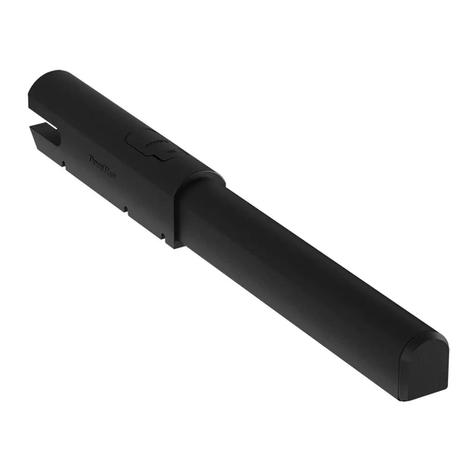
Swing-4000 electromechanical linear operator is designed to automate a two-wing swing gate with rigid frame.
Operator body consists of two silumin parts, in which the gear motor and the lead screw are located.
Worm gear and planetary reduction gear form a self-locking system that provides mechanical locking of the gate leaf when the
motor is switched off. A convenient and safe release system allows you to manually open or close the gate leaf in case of power
outage or control unit malfunction. The automatic system is operated by a remote control unit in a shockproof sealed housing.
1.1. Specifications
GENERAL INFORMATION
Characteristics Value
Power supply 220–240 V / 50, 60 Hz
Power consumption 140 W
Consumed current 1,8 А
Speed 1,8 sm/sec
Maximum leaf length 4 m
Maximum leaf weight 400 kg
Temperature protection 150 °C
Cover protection class IP44
Intensity 50 %
Operating temperature -20…+55 °C
Gate leaf length, m Gate leaf weight, kg
2,5 400
3 350
3,5 300
4 250
Operating range
1.2. Carton inventory
After receiving the device, it must be unpacked and inspected for damage. In case of any defects, please contact the supplier
of the device.
The operator components included in the standard package are listed in the following table.
# Name Qty
1 Operator 2 pcs (left/right)
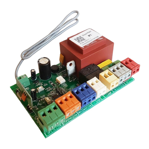
2 Control unit* 1 pc
3 Key-switch* 1 pc
4 Photocells* 1 pair
5 Signal lamp* 1 pc
6 Release key 2 pcs
7 Rear bracket 2 pcs
8 Front bracket 2 pcs
9 Hardware set 2 pcs
10 Owner’s manual 1 pc
*optional accessories (not provided)

3
2. SAFETY RULES
WARNING! To reduce the risk of injury or death read and follow all instructions. Save these instructions.
Carefully follow all the instructions specified herein. Failure to do so could cause equipment damage and/or personal
injury.
Swing-4000 is designed to operate swing gates. Use the operator only for its intended purpose, any other use is pro-
hibited.
The manufacturer assumes no liability for damage or injury to persons or property which occur as a result of incorrect
use of the operator.
Prior to operator installation verify the gate operates smoothly.
Installation must be performed in accordance with the standards EN12453 and EN 12445. For countries, which are not
EC members, these requirements are to be met.
Verify the gate conforms to EN12604 and EN 12605 standards (see gate documentation). For countries, which are not
EC members, the above mentioned requirements shall be met in order to obtain appropriate safety level.
Mechanical units of the gate shall conform to EN12604 and EN 12605 standards.
Make sure that the installation site meets the climatic conditions of the operator.
Do not install the operator in premises where there are flammable substances or other hazardous environments, as this
may cause an explosion or fire.
Use tools specified in «Tools» section hereof during assembly, installation and adjustment of the operator.
When performing operation at height, use a stable support.
The operator is not designed for installation at height over 2,5 m.
Always wear protective gloves and eye protection when drilling.
To fasten the product, use the hardware supplied with the operator or the corresponding one.
Always disconnect electrical power prior to installation, cleaning or maintenance of the operator.
If the operator is to be used with the gate having a built-in pass door it is required to install an additional safety device
preventing operator actuation when the pass door is open.
Make sure no objects will get jammed between movable and stationary parts of the operator.
Use only DoorHan accessories, as other manufacturers accessories may cause the automatic system to malfunction.
DoorHan Company assumes no liability for unstable operation of the automatic system when using safety devices and
accessories produced by other than DoorHan manufacturers without the approval of DoorHan.
Never leave operator motor disengaged as it may cause uncontrolled movement of the gate leaves and as a result their
damage.
Never use the operator if it needs to be repaired or adjusted. Incorrect operator or door installation may cause severe injury.
The manufacturer assumes no liability for incorrect installation or damage occurred during operation.
Since the operator has no power cord with a plug it shall be connected to the mains supply via automatic switch with
a minimal distance of 3 mm between the neighbouring contacts. It is recommended to use a 6 А double-pole circuit
breaker.
Before starting the operator make sure there are no foreign objects in the operator working zone.
Do not make any changes to the automatic system that are not specified in this manual.
Remove the product packaging and dispose of it. Do not leave packaging materials within reach of children.
Never allow children to play in the gate area while the operator is in operation. All remote controls, as well as stationary
control buttons, must be inaccessible to children.
Walk or drive through only when the gate is fully opened and the operator is on stop.
The contents of the instructions may not serve as a basis for any kind of claims.
The manufacturer reserves the right to make any changes to the product construction, structure, components and ac-
cessories without notice.
Having installed the operator verify all the mechanisms are correctly adjusted, safety devices and manual release func-
tion properly.
WARNING! Always install mechanical stops to limit the travel of gate leaves if the operator has no limit switches (option).
SAFETY RULES

4
OPERATOR DESIGN
3. OPERATOR DESIGN
4. INSTALLATION
4.1. Tools
1. Set of spanners
2. Set of slotted and cross screwdrivers
3. Set of drills for metal
4. Set of drills for concrete
5. Pliers
6. Hacksaw for metal
7. Electric drill
8. Tape measure (folding rule)
1. Motor
2. Power cable
3. Rear bracket
4. Front bracket
5. Housing
6. Limit switches
1
4
5
6
3
2
1175
640
200
90 90
535
Unit: mm

5
WARNING! RISK OF INJURY!
Have a qualified technician lay the 380-400 V AC cables. The cables must be laid in protective corrugated tubes. Avoid
contact of cables and moving parts of the gate. In case of supply cable damage, use the suitable type of the cable.
INSTALLATION
4.2. Scheme of operator installation and cable laying
Cables necessary for installation of Swing-4000 and accessories (if available):
Cable 2 × 0,5 mm2 (photocell transmitter, step-by-step control button).
Cable 4 × 0,5 mm2 (photocell receiver).
Cable 4 × 1,5 mm2 (power supply).
Cable 3 × 0,5 mm2 (limit switches).
Use cables with appropriate insulation.
WARNING! Use 4 × 1,5 mm and 3 × 0,5 mm cables to connect the operator.
It is recommended to use 4 × 1,5 mm cable to connect the operator motor, and 3 × 0,5 mm cable to connect the limit
switches.
Connect the operators motors to the following terminals of the control board: OP (black), CL (brown), COM (blue) (М1)
and OP (black), CL (brown), COM (blue) (М2) respectively.
Limit switches should be also connected per the colour coding to the control board (COM — blue; OP — black; Cl —
brown).
Supplied capacitors should be connected to OP and CL (M1) and OP and CL (M2) terminals of the control board re-
spectively.
1. Operator
2. Control unit
3. Photocells (option)
4. Signal lamp (option)
5. Key-switch (option)
4 × 1,5
3 × 0,5
4 × 0,5
2 × 0,5
2 × 0,5
1 1
5
4
3
2
3
4 × 1,5
3 × 0,5

6
INSTALLATION
Gate leaf opening angle А, mm В, mm С, mm D, mm
90°180 200 100 1 010
120°160 160 60 1 019
Gate leaf opening angle А, mm В, mm D, mm
90°180 200 1 010
4.3.Installation dimensions
A
Column
B
C
D
Hinge
Gate leaf
(closed)
A
B
D
Outside property
Inside property
Opening inwards Opening outwards

7
Fasten the rear bracket to the column with anchor bolts. When fastening to a brick column screw anchor bolts into the brick
body not in the mortar. Mounting methods are shown in the figures below.
4.4. Operator installation
WARNING! Before installing the operator verify the gate moves smoothly and there is enough space to securely attach
the operator to the column and gate leaf.
Concrete column
Fasten the front bracket to a gate leaf.
Brick column
When mounting the rear and front brackets, make sure they are on the
same level.
Fasten the sliding part of the operator to the front bracket.
Attach the operator. Fasten the operator to the rear bracket.
INSTALLATION
Pre-install a
steel bracket

8
Brackets mounting angle depends on the gate opening parameters and is adjusted directly at the installation site.
Rear bracket mounting angle
Front bracket mounting angle
98 mm
90 mm
95 mm
78 mm
68 mm
40 mm
28 mm
158 mm
145 mm
55 mm
60 mm
155 mm
120 mm
114 mm
INSTALLATION

9
LIMIT SWITCH ADJUSTMENT
6. EMERGENCY RELEASE
Use emergency release to disengage the operator in case of a power failure.
Turn the release lever 90° to disengage the operator.
WARNING! The motor should be unlocked only when the power is off.
2
closed position
limit switch
5.2. Closed position limit switch
1. Close the gate leaf.
2. Unscrew the mounting screws of the closed position limit switch (option).
3. Move the limit switch (option) along the guide until the switch is activated. SwCl LED on the control board will light when
the switch is activated.
4. Secure the switch (option).
5. LIMIT SWITCH ADJUSTMENT
1
open position
limit switch
5.1. Open position limit switch
1. Release the operator and fully open the gate leaf.
2. Unscrew the mounting screws of the open position limit switch (option).
3. Move the limit switch (option) along the guide until the switch is activated. SwOp LED on the control board will light when
the switch is activated.
4. Secure the switch (option).

10
WARNING! After operator installation is finished test the emergency release system. Unbalanced or damaged gate may
cause uncontrolled movement of the operator moving parts when emergency release system is used.
7. MAINTENANCE
It is required to carry out regular servicing of the operator in accordance with applicable regulations and legislation, paying
special attention to safety rules, and attracting trained service personnel.
The operator requires scheduled maintenance every 6 months or 5 000 cycles after the last maintenance. Service the
operator taking into consideration Safety Rules section of this Manual.
Disconnect all power (AC, battery) to the operator before servicing.
Check all gate and operator parts for signs of wear and tear. Replace all worn parts.
Check the operator for signs of coming out grease.
Verify the end positions of gate travel are properly adjusted. Adjust if necessary.
Clean the outer surfaces of operator, safety devices, electromechanical or electromagnetic lock (when used) with a soft,
damp cloth. Never use water jets, high pressure cleaners, acids or alkalis for cleaning.
EVERY MONTH verify all the safety devices work properly. Should any failure occur call for a trained technician to fix it.
Average product life is 10 years or 50 000 cycles.
The product life and number of cycles are approximate. They have been statistically determined for typical operating
conditions and are not guaranteed on a case-by-case basis. These characteristics refer to the period of operation of the
equipment during which there is no need for special maintenance.
Each automatic entrance group has a number of technical characteristics, such as friction, balancing, environmental
conditions, which can significantly affect the product life and operational quality of the entrance group or part of its com-
ponents (including automation).
Failure Possible reason Remedy
Operator does not work
power switched off or failed verify the power is ON
obstruction to gate movement remove the obstruction
poor wire connection check wiring for secure connection
operator is disengaged engage the operator
Operator stops unexpectedly operator thermal protection is activated let the operator to cool down
Gate does not close/open fully incorrect operator programming reprogramm the operator
8. TROUBLESHOOTING
MAINTENANCE
Release
Release
Engage
Engage

11
NOTES

We very much appreciate that you have chosen
the product manufactured by our company and
believe that you will be satisfied with its quality.
For information on purchasing, distribution and
servicing contact DoorHan central office at:
120 Novaya street, Akulovo village,
Odintsovo district, Moscow region,
143002, Russia
Phone: +7 495 933-24-00
E-mail: [email protected]
www.doorhan.com
Table of contents
Other DoorHan Gate Opener manuals

DoorHan
DoorHan SHAFT-120 User manual

DoorHan
DoorHan SLIDING-1300 User manual

DoorHan
DoorHan Sectional-500 User manual

DoorHan
DoorHan SECTIONAL-800PRO-CE User manual

DoorHan
DoorHan SWING-3000PRO User manual

DoorHan
DoorHan SHAFT-30 User manual

DoorHan
DoorHan SLIDING-3000 User manual

DoorHan
DoorHan PHOTO-W User manual

DoorHan
DoorHan Swing-2500 User manual

DoorHan
DoorHan Sectional-1000 User manual
Popular Gate Opener manuals by other brands

Entrematic
Entrematic Ditec NeoS manual

GiBiDi
GiBiDi TOP EVO 291E/S Instructions for installation

Grant's Automation
Grant's Automation e-Gate SWG-12V user manual

GiBiDi
GiBiDi MEKA BL 12 Instructions for installation

Entrematic
Entrematic OBBI3BH Original instruction

Entrematic
Entrematic Ditec PWR50H Technical manual