BelFox Jupiter 250 User manual

Drehtorantrieb
Swing gate operator
Opérateur pour portails pivotants
Jupiter 250
Montageanleitung - Mechanik
Instruction manual - Mechanics
Notice de montage - Mécanique
Version Jan. 2018

2
Allgemeine Angaben
Sicherheitshinweise
-Die Montageanleitung muss beachtet werden.
-Bei Nichtbeachtung der Montageanleitung wird eine Haftung des Herstellers
ausgeschlossen.
-Nehmen Sie kein beschädigtes Tor oder beschädigten Torantrieb in Betrieb!
-Die gültigen Richtlinien müssen beachtet werden, z.B. EN 12453, EN 12604,
EN 12605.
-Die Benutzer müssen in die Funktionen der Anlage eingewiesen werden.
-Arbeiten an der Anlage dürfen nur im spannungsfreien Zustand durchgeführt
werden.
-Nur Originalersatzteile und Originalzubehör verwenden!
General remarks
Safety instructions
- The mounting instructions must be adhered to.
- The manufacturer assumes no liability for any damages resulting from
the non-adherence to these mounting instructions.
- Do not commission any defect gate or gate operator.
- The relevant directives must be adhered to e.g. EN 12453, EN 12604
and EN 12605.
- The users must be initiated in the individual operations of the device.
- Any work relating to the device can only be done when there is no supply
voltage.
- Use only original spare and component parts.
Informations générales
Consignes de sécurité
- Veuillez suivre scrupuleusement les instructions de montage et respecter le
mode d’emploi ci-présent.
- Le fabricant décline toute responsabilité en cas de dégradations dues au
non-respect des recommandations fournies dans ce document.
- Veuillez n’employer que des portails et dispositifs en parfait état de marche.
- Toutes les Normes européennes et les directives en vigueur, telles que EN
13241-1, doivent être respectées.
- Les utilisateurs doivent être initiés au fonctionnement du système.
- Tous travaux sur l’opérateur doivent être effectués hors de tension.
- Utilisez exclusivement que des pièces et fournitures originales.

3
Inhaltsverzeichnis:
2) Technische Daten..............................................................................................................4
3) Wirkungsweise ..................................................................................................................5
4) Lieferumfang......................................................................................................................5
5) Abmessungen/Montagemaße............................................................................................6
6) Montage des Antriebes......................................................................................................7
7) Einstellen der Endschalter.................................................................................................8
7.1) Einstellen des Endschalters „ZU“ ......................................................................................8
7.2) Verschieben der Endschalter.............................................................................................9
7.3) Einstellen des Endschalters „AUF“....................................................................................9
8.) Notentriegelung...............................................................................................................10
8.1) Verriegeln des Antriebes.................................................................................................11
9) Kabelplan ........................................................................................................................11
10) Wartung der Toranlage....................................................................................................12
11) Elektrischer Anschluss ....................................................................................................12
12) Konformitätserklärung ................................................................................................13/14
Table of contents:
13) Mode of operation............................................................................................................15
14) Scope of delivery.............................................................................................................15
15) Dimensions/mounting dimensions...................................................................................16
16) Mounting of the operator .................................................................................................17
17) Adjustment of end switches.............................................................................................18
17.1) Adjustment of end switch “CLOSED”...............................................................................18
17.2) Altering the position of end switches ...............................................................................19
17.3) Adjustment of end switch “OPEN”...................................................................................19
18) Emergency release..........................................................................................................20
18.1) Locking the operator ......................................................................................................21
19) Cable layout.....................................................................................................................22
20) Maintenance....................................................................................................................23
21) Electrical connection .......................................................................................................23
22) Declaration of conformity ..........................................................................................24/25
Sommaire:
23) Mode de fonctionnement.................................................................................................26
24) Contenu de la livraison....................................................................................................26
25) Dimensions/dimensions de montage...............................................................................27
26) Montage de l’opérateur....................................................................................................28
27) Réglage des commutateurs de fins de course ................................................................29
27.1) Réglage du commutateur de fin de course « FERME » ..................................................29
17.1) Modification la position des commutateurs de fin de course ...........................................30
27.3) Réglage du commutateur de fin de course « OUVERT »................................................30
28.) Déverrouillage d’urgence.................................................................................................31
28.1) Verrouiller l’opérateur ......................................................................................................32
29) Plan de câblage...............................................................................................................33
30) Maintenance....................................................................................................................34
31) Raccordements électriques.............................................................................................34
32) Déclaration de conformité CE.....................................................................................35/36

4
2. Technische Daten 2. Technical data 2. Données techniques
Netzanschluss
mains supply
alimentation
secteur
230V / 50 –60 Hz
Motorspannung /
Strom
motor voltage/
current
tension
moteur
12V DC 5A
Motorbremse
engine brake
frein moteur
12V DC 1,5 A
Leistung
engine output
puissance du
moteur
118 W
Öffnungszeit bei 900
C
Opening time
at 900C
temps
d’ouverture à
900C
Typisch. 15 sek
Generally 15 sec.
En général 15 sec.
Arbeitshub max.
maximum
power stroke
course max.
de travail
330 mm
Max. Kraft
Maximum
force
force max.
2000 N
Temperaturbereich
temperature
range
plage des
températures
-200C bis +500C
from 200C to + 500C
de 200C à + 500C
max. Bewegungsfreq.
maximum
movement
frequency
fréquence
max de mou-
vements.
20 x Stunde
20 x per hour
20 x par heure
max. Flügellänge
maximum
wing length
longueur
max. du van-
tail
2,5 m
max. Torgewicht
maximum ga-
te weight
poids max.
du portail
200 kg

5
3. Wirkungsweise
Der Antrieb arbeitet elektromechanisch. Ein 12 V Gleichstrommotor treibt eine
Spindel an. Über eine fest mit der Spindelmutter verbundene Schubstange wird
die Spindel aus dem Antriebskörper heraus- oder hineingeschoben und dadurch
das Tor bewegt.
Bei Erreichen der eingestellten Endlagen schaltet der Antrieb automatisch über
Endschalter ab.
Bei Torflügeln über 2 m oder 2-flügeligen Toranlagen empfiehlt es sich, einen
Toranschlag in „TOR ZU“-Stellung anzubringen. Als zusätzliche Verriegelung
kann ein Elektroschloss eingebaut werden.
Der Antrieb ist selbsthemmend. Das Tor kann im verriegelten Zustand (Normalbe-
trieb) von Hand nicht aufgeschoben werden, ohne dass der Antrieb oder die Be-
schläge beschädigt werden. Sollte die Selbsthemmung des Antriebes nicht aus-
reichen, so muss ein zusätzliches Elektroschloss eingebaut werden.
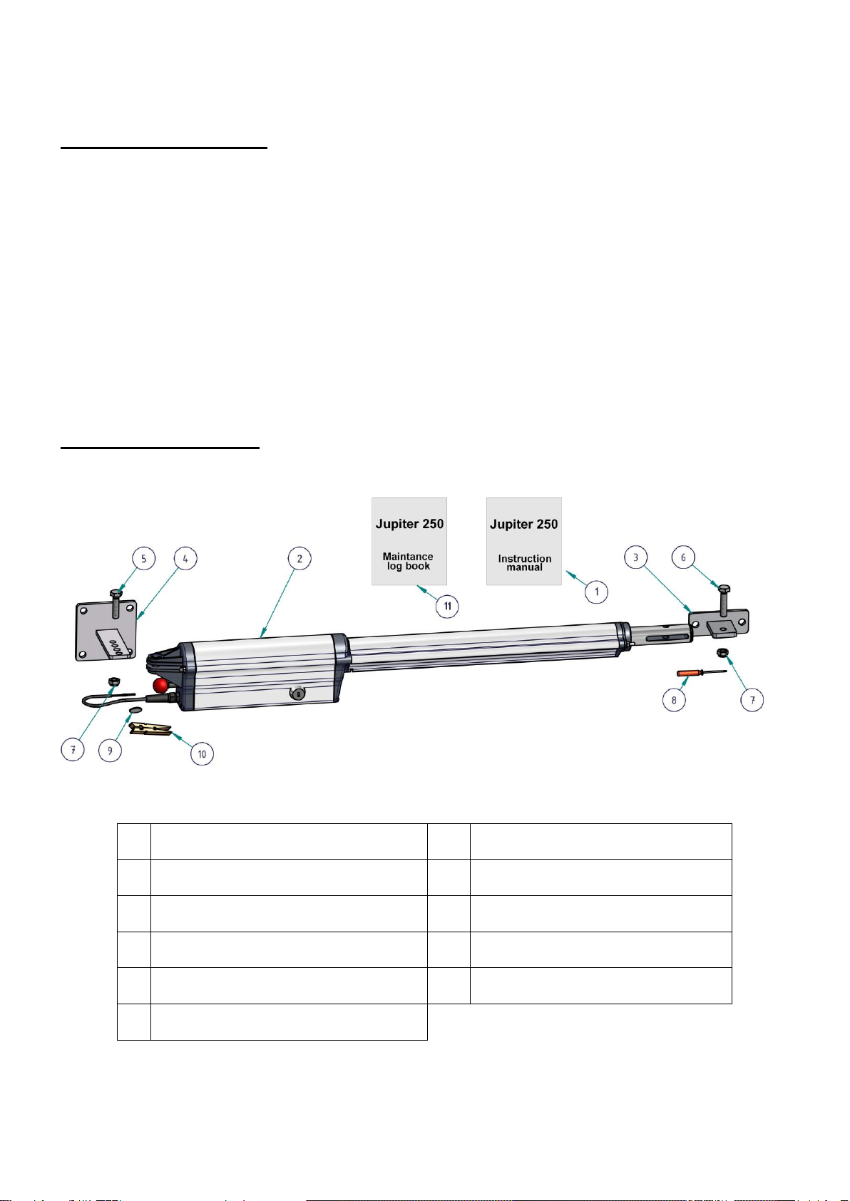
4. Lieferumfang
(1)
1St. Montageanleitung
(7)
2St. Splinte 3,2 x 20
(2)
1St. Antrieb Jupiter 250
(8)
1St. Schraubendreher klein
(3)
1St. Beschlag für Torflügel
(9)
1St. Knopfzelle 3V
(4)
1St. Beschlag für Pfeiler/Pfosten
(10)
1St. Klammer
(5)
1St. Splintbolzen 10 x 36
(11)
1St. Prüfbuch
(6)
1St. Splintbolzen 10 x 36

6
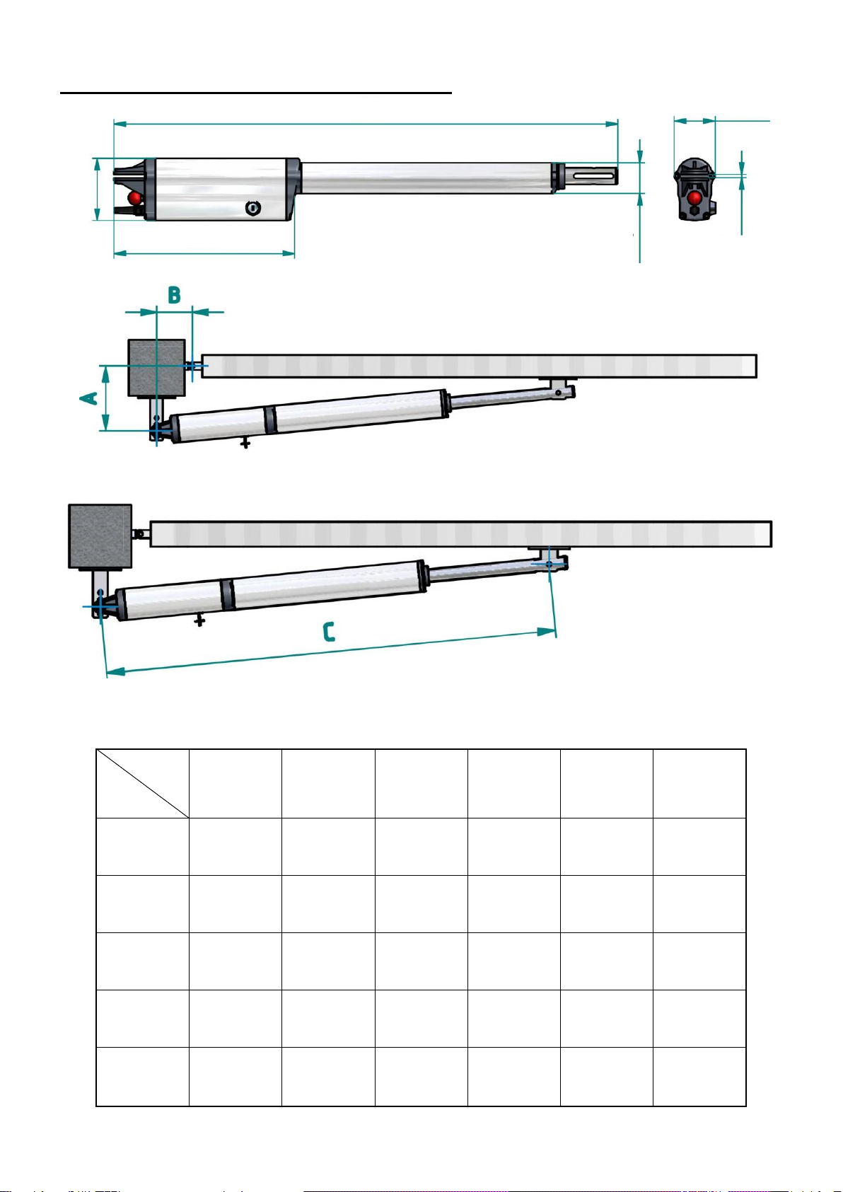
5. Abmessungen / Montagemaße
Beim Einbau des Antriebes müssen die Montagemaße (Maße in mm) eingehalten werden
A
B
90
C
100
C
110
C
120
C
130
C
140
C
100
1070
1125
1020
1125
980
1130
940
1130
920
1135
900
1145
120
1100
1135
1070
1140
1030
1145
990
1150
970
1150
950
1155
140
1130
1145
1100
1150
1080
1155
1050
1160
1030
1165
1000
1170
160
1170
1165
1130
1170
1090
1175
1050
1175
1010
1180
970
1180
180
1200
1200
1110
1180
1060
1185
1000
1185
970
1185
940
1190
921
340
74
55,5
112
6

7
6. Montage des Antriebes
Hinweis: Der Anbau des Antriebes ist denkbar einfach. Vor Beginn der Mon-
tage sollte jedoch die Montageanleitung sorgfältig gelesen werden. Einbau-
fehler können dadurch vermieden, Zeit und Ärger erspart werden. Für die
Beschädigung des Antriebes durch fehlerhafte Montage kann der Hersteller
keine Gewährleistung übernehmen.
Für die einwandfreie Funktion des Antriebes ist ein leichtgängiges Tor ohne
Stützräder Bedingung. Die Angeln sollten spielfrei sein. Für Tore mit großer
Windlast ist dieser Antrieb nicht geeignet.
Signalleitungen dürfen eine Länge von 30m nicht überschreiten. Ab einer
Kabellänge von 5m ist ein abgeschirmtes Kabel zu verwenden.
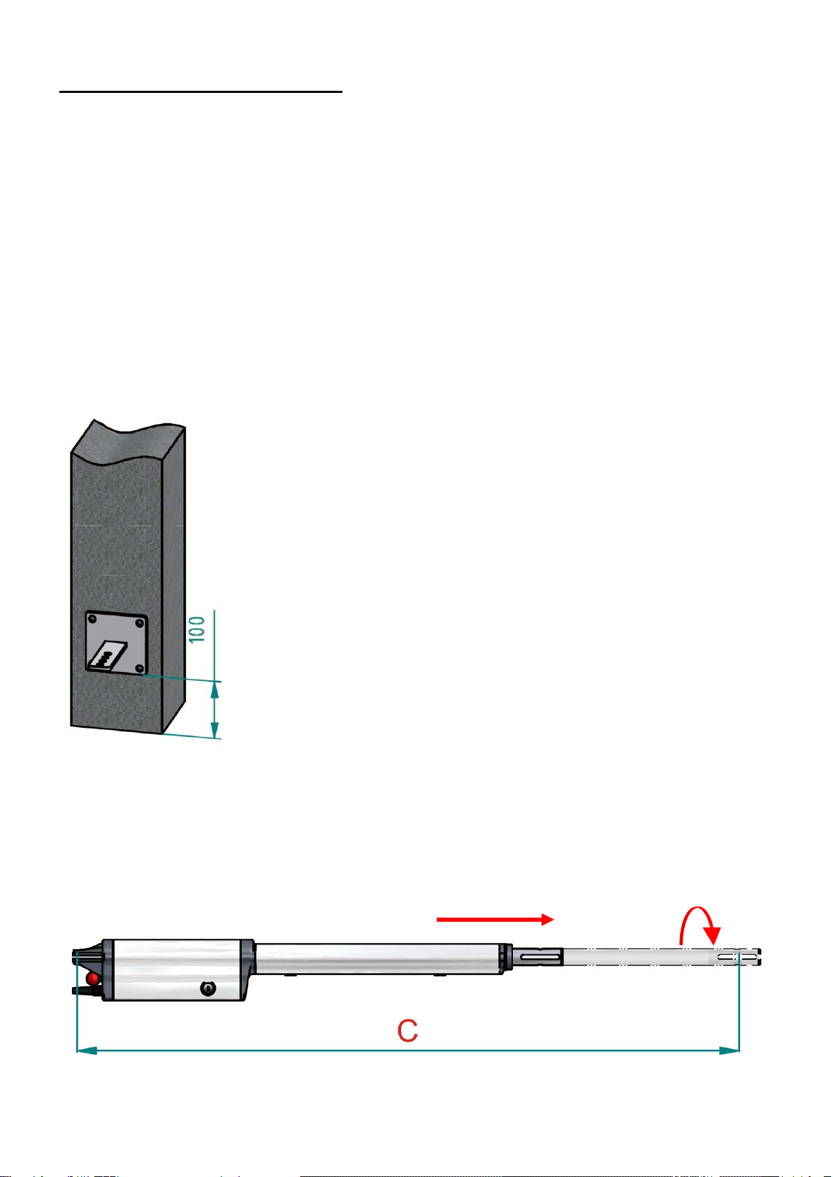
Messen Sie entsprechend dem Pfosten/Pfeiler das Maß
A und B (siehe Seite 6 Punkt 5, „Abmessungen / Monta-
gemaße“) aus und befestigen Sie den Pfosten-
/Pfeilerbeschlag an dem Torpfosten/-pfeiler.
(Die Pfosten-/Pfeilerbeschläge können angeschweißt
oder angeschraubt werden. Wird der Pfosten-
/Pfeilerbeschlag angeschraubt, so sind Dübel zu wählen,
welche sich im Betrieb nicht lockern können. Am besten
eignen sich Klebe-Verbundanker.)
Der Abstand vom Boden bis zur Unterkante des Pfosten-
/Pfeilerbeschlages muss mindestens 100 mm betragen.
Drehen Sie die Schubstange solange heraus, bis das Maß C (siehe Seite 6
Punkt 5, „Abmessungen / Montagemaße“) erreicht ist. Kontrollieren Sie die
waagrechte Ausrichtung des Antriebes.
Nun befestigen Sie den Torflügelbeschlag an dem geschlossenen Tor.

8
7. Einstellen der Endschalter
Lösen Sie den Antrieb von dem Pfosten-/Pfeilerbeschlag und dem Torflügel-
beschlag und befestigen den Antrieb mit der Unterseite nach „Oben“ wieder
an dem Pfosten-/Pfeilerbeschlag und dem Torflügelbeschlag. Somit wird die
Einstellung der Endschalter erleichtert.
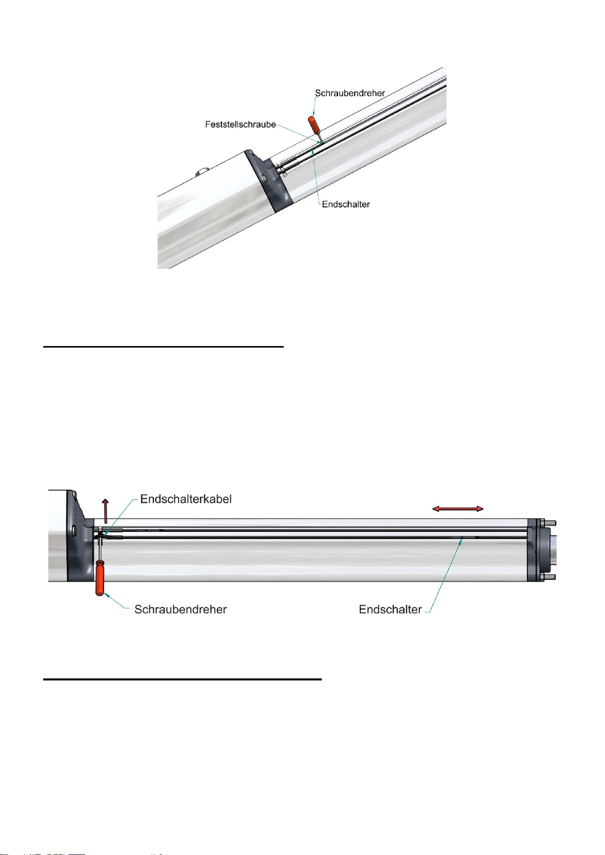
7.1 Einstellen des Endschalters „ZU“
Klemmen Sie die Anschlussleitung des Antriebes mit der Klammer an die
mitgelieferte 3V Knopfzelle, so dass die Leuchtdiode des Endschalters „ZU“
leuchtet.
Lösen Sie nun die Feststellschraube (siehe Seite 9 Punkt 7.2 „Verschieben
der Endschalter“) des Endschalters „ZU“ und verschieben diesen so lange in
Richtung Motorgehäuse, bis die Leuchtdiode des Endschalters „ZU“ erlischt.
Jetzt hat der Endschalter „ZU“ die richtige Position.
9
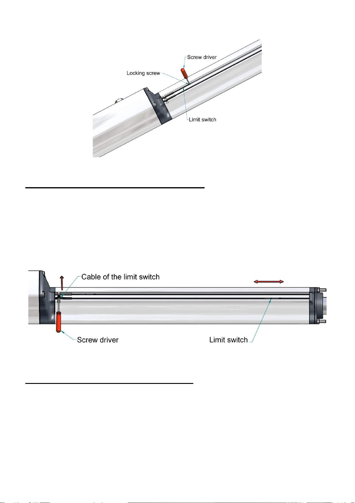
7.2 Verschieben der Endschalter:
Mit dem mitgelieferten Schraubendreher können Sie das Endschalterkabel
aus dem Führungsprofil herausheben. Nach dem Lösen der Feststell-
schraube des Endschalters kann dieser durch Schieben oder Ziehen an dem
Endschalterkabel verstellt werden. Ist der Endschalter richtig eingestellt, so
muss dieser durch die Feststellschraube wieder befestigt werden. Das restli-
che Endschalterkabel wird in das Motorgehäuse eingeschoben.
7.3 Einstellen des Endschalters „AUF“
Entriegeln Sie den Antrieb mit Hilfe der Notentriegelung (siehe Seite 10
Punkt 8 „Notentriegelung“) und schieben das Tor in die gewünschte Stellung
„AUF“. Wechseln Sie nun die Anschlussdrähte an der 3 V Knopfzelle, so
dass die Leuchtdiode des Endschalters „AUF“ leuchtet. Lösen Sie nun die
Feststellschraube des Endschalters „AUF“ und verschieben diesen so lange
in Richtung „Schubstange-Ende“, bis die Leuchtdiode des Endschalters
„AUF“ erlischt. Jetzt hat der Endschalter „AUF“ die richtige Position.
10
Entriegelungsknopf
(nach hinten gezogen)
Gummitülle
Schloss
(Innenteil herausgesprungen)
Entriegelungsknopf
Gummitülle
Schloss
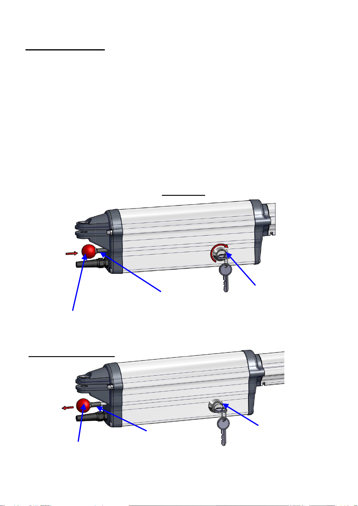
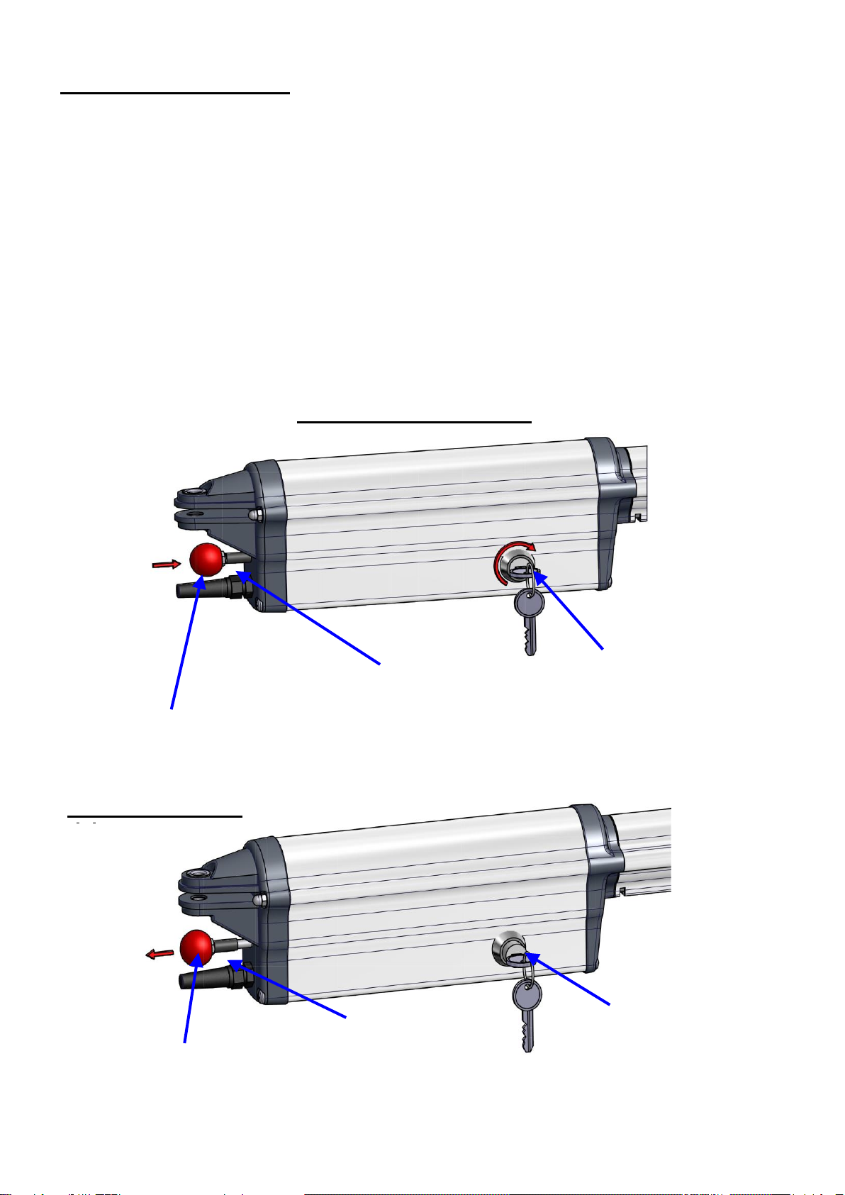
8. Notentriegelung
(Notentriegelung nur im stromlosen Zustand durchführen!)
Bei Stromausfall kann das Tor von Hand geöffnet oder geschlossen werden,
unabhängig davon in welcher Stellung es sich gerade befindet.
Um den Antrieb notzuentriegeln drehen Sie den Schlüssel 450 nach rechts.
Das Innenteil des Schlosses muss ca. 1,5 cm nach Außen springen. Wenn
das Innenteil des Schlosses nicht nach Außen springt, müssen Sie den Ent-
riegelungsknopf in Richtung „Motorgehäuse“ drücken und das Innenteil des
Schlosses mit Hilfe des Schlüssels nach Außen ziehen. (Dadurch entriegelt
sich das Motorhalteblech und der Motor wird von der Schubspindel getrennt.
Der Entriegelungsknopf muss sich deutlich nach hinten bewegen.)
Der Torflügel kann von Hand bewegt werden.
Entriegeln
Entriegelter Zustand
11
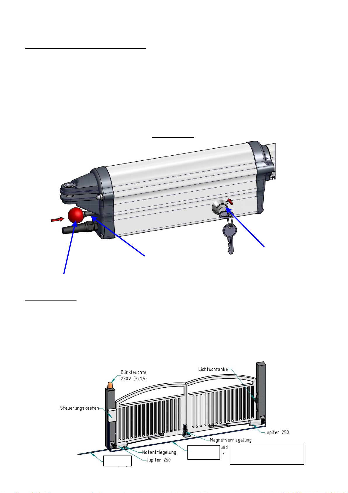
8.1 Verriegeln des Antriebes:
Schieben Sie den Entriegelungsknopf in Richtung „Motorgehäuse“, bis das
Innenteil des Schlosses in die Halterung des Motorbleches eingeschoben
werden kann.
Die richtige Stellung der Verriegelung erkennen Sie daran, dass die Gum-
mitülle leicht gestaucht ist. Jetzt kann der Schlüssel wieder abgezogen wer-
den.
Das Tor lässt sich nun wieder automatisch betreiben.
9. Kabelplan
An dem Antrieb ist bereits ein Versorgungskabel (12V) von 100cm Länge
installiert. Die Anschlüsse der Endschalter sind in dem Motorgehäuse ver-
schaltet und müssen nicht nach Außen geführt werden.
Die Motorleitung von der Steuerung zum Motorkabel muss bei einer Länge
bis 4m mit einem Querschnitt von 2x1,5mm2und bei einer Länge über 4m
mit einem Querschnitt von 2x2,5 mm2verlegt werden.
Verriegeln
Entriegelungsknopf
Gummitülle
Schloss
Zuleitung
230V (3x1,5)
Lichtschranke
(4x0,8)
Motorleitung
12V (2x1,5) bis 4m Länge
12V (2x2,5) ab 4m Länge

12
10. Wartung der Toranlage
Kraftbetätigte Toranlagen müssen vor der ersten Inbetriebnahme und min-
destens einmal jährlich einer fachgerechten Sicherheitsprüfung/-wartung
durch einen Sachkundigen unterzogen werden. Die Durchführung der Prü-
fung und deren Ergebnisse sind im mitgelieferten Prüfbuch festzuhalten.
Die Schubstange sollte unabhängig von der Sicherheitsprüfung/-wartung
einmal im Jahr von außen mit einem sauberen Tuch gereinigt und mit Sili-
konspray leicht eingesprüht werden.
11. Elektrischer Anschluss
Hierzu verwenden Sie die Montageanleitung „Motorsteuerung 47-31-250“.

13
12. EG –Konformitätserklärung
BelFox Torautomatik
Produktions- u. Vertriebs GmbH
Gewerbestrasse 3+5
D –36148 Kalbach
Wir erklären hiermit, dass die nachstehend aufgeführten Geräte allen einschlägigen zutreffenden EG-
Richtlinien und Normen entsprechen:
Gerätebezeichnung: Drehtorantrieb Jupiter - 250
Angewandte Richtlinien und Normen sind unter anderem:
EMV –Richtlinie (2014/30/EU)
Maschinenrichtlinie (2006/42/EG)
Niederspannungsrichtlinie (2014/35/EU)
Funkanlagenrichtlinie RED (2014/53/EU)
RoHS (EU-Richtlinie 2011/65/EU)
Nutzungssicherheit kraftbetätigter Tore, Anforderungen (EN 12453)
Nutzungssicherheit kraftbetätigter Tore, Prüfverfahren (EN 12445)
Angewandte harmonisierte Normen, deren Fundstellen im Amtsblatt der EU veröffentlicht worden sind:
DIN EN 61000-6-2
DIN EN 61000-6-3
DIN EN 60335-1:2012
DIN EN 60335-2-103
Die Übereinstimmung wurde nachgewiesen durch:
Technischer Bericht „funktionale Sicherheit“, insbesondere EN 60335-1,
TÜV Süddeutschland
Dudenstr. 28
D-68167 Mannheim
Erstprüfung nach DIN EN 13241-1
RWTÜV Systems GmbH
Langemarckstr. 20
D-45141 Essen
Ort: D-36148 Kalbach Datum: 01.06.2017
Unterschrift des gesetzlich Haftenden: ________________________
Name und Funktion: Edgar Fierle, Geschäftsführer

14
Seite 2 zur EG-Konformitätserklärung Drehtorantrieb Jupiter-250
Aufgrund der auf Seite 1 aufgeführten Normen und dem Nachweis der Übereinstimmung
des geprüften Antriebes mit diesen Normen sowie dem Prüfbericht von RWTÜV Systems
vom 03.03.2010 ist der Betrieb des Antriebes Jupiter-250 wie folgt zulässig:
Betrieb bis 200 Kilogramm Torgewicht und 2,5 Meter Torbreite ohne Sicherheitskontakt-
leiste.
Ausdrücklich wird darauf hingewiesen, dass weitere Sicherheitseinrichtungen wie bei-
spielsweise Lichtschranken zur Ausrüstung eines kraftbetätigten Tores notwendig sein
können.
15
Mounting instructions- mechanics
13. Mode of operation
The device is operated electromechanically. A 12 V DC motor drives a shaft. A
driving rod attached to the screw nut pushes the shaft out of or into the drive unit
thus moving the gate. As soon as the operator reaches the end positions which
have been set before it automatically stops by means of the end switches.
When the wings of the gate exceed 2 m or a gate is provided with two wings it is
recommendable to mount a stopper in the position “GATE CLOSED”. To have an
additional locking device, you can install an electronic lock.
The operator is self-locking. When the gate is locked (normal operation), it is not
possible to open it manually without doing damage to the operator or the sheath-
ing. If the self-locking capacity of the gate is insufficient, you have to install an
electronic lock in addition.
14. Scope of delivery
(1)
1 x Instruction manual
(7)
2 x cotter-pin 3,2 x 20
(2)
1 x operator Jupiter 250
(8)
1 screwdriver small
(3)
1 x sheathing for gate wing
(9)
1 button cell 3 V
(4)
1 x sheathing for pile
(10)
1 x clamp
(5)
1 x hexagon bolt M10x40
(11)
1 x maintance log book
(6)
1 x hexagon bolt M10x45
(12)
1 x silicone aerosol
16
15. dimensions / mounting dimensions
When mounting the operator you have to stick to the mounting dimensions (in mm).
A
B
90
C
100
C
110
C
120
C
130
C
140
C
100
1070
1125
1020
1125
980
1130
940
1130
920
1135
900
1145
120
1100
1135
1070
1140
1030
1145
990
1150
970
1150
950
1155
140
1130
1145
1100
1150
1080
1155
1050
1160
1030
1165
1000
1170
160
1170
1165
1130
1170
1090
1175
1050
1175
1010
1180
970
1180
180
1200
1200
1110
1180
1060
1185
1000
1185
970
1185
940
1190
921
74
112
340
55,5
6
17
16. Mounting of the operator
Note: The mounting of the operator is absolutely easy. Nevertheless you
should carefully read the mounting instructions before starting the mounting.
This prevents you from making any mistake and allows you to save time and
to avoid trouble. The manufacturer cannot assume any liability for any dam-
age of the operator which results from an incorrect mounting.
In order to make sure that the operator works without any difficulty a smooth-
running gate without stabilizers is required. The hinges should be free of
clearance. This operator is not appropriate for gates exposed to a heavy
wind load.
Signalling lines may not exceed the length of 30 m. As soon as the length of
the cable exceeds 5 m you have to use a shielded cable.
Measure the dimension A and B (see page 16) according
to the pile and fix the sheathing of the pile to the pile it-
self.
(The sheathings can be welded or screwed. If the
sheathing is screwed, you have to choose anchor bolts
which do not loosen when the operator is active. The
best solutions are adhesive shear connectors).
The distance from the floor to the bottom edge of the
sheathing of the pile has to amount to at least 100 mm.
Now fix the sheathing of the gate wing to the closed gate in such a way that
the dimension C (see page 16, point 15 “dimensions/mounting dimensions“)
is not neglected. In order to do so turn the driving rod as long as the dimen-
sion C is reached. Check the horizontal alignment of the operator.

18
17. Adjustment of end switches
Remove the operator from the sheathing of the pile and the sheathing of the
gate wing and fix it once again with the rear side pointing to “the top “. This
makes it easier to adjust the end switches.
17.1 Adjustment of end switch “CLOSED “
Using the clamp attach the connecting cable to the 3 V button cell included
in the delivery. This makes the LED of the end switch “CLOSED “flash.
Now remove the locking screw of the end switch “ CLOSED “ (see page 19 ,
point 17.2 “Altering the position of end switches”) and move it towards the
crankcase until the LED of the end switch “CLOSED” ceases to flash. Now
the end switch “CLOSED” has reached the correct position.
19
17.2 Altering the position of end switches:
Using the screw driver included in the delivery you can remove the end
switch cables from the guiding profile. After having released the locking
screw of the end switch, you can alter its position by moving or pulling the
cable of the end switch. When the end switch has reached the correct posi-
tion, you have to fix it again using the locking screw. The remaining cable of
the end switch is introduced into the crankcase.
17.3 Adjustment of end switch “OPEN “
Unlock the operator using the emergency release (see page 20, point 18
“emergency release “) and move the gate until it reaches the desired posi-
tion “OPEN “. Now exchange the connecting wires at the 3V button cell so
that the LED of the end switch “OPEN” will start to flash. Release the lock-
ing screw of the end switch “OPEN” and move it towards “ the end of the
driving rod “ until the LED of the end switch “OPEN” ceases to flash. Now
the end switch “OPEN” has reached the correct position.
20
release button
(pulled backwards)
grommet
lock
(inner part outwards)
release button
grommet
lock
18. Emergency release
(Only make an emergency release when the operator is disconnected from
the mains)!
When there is a mains failure, you can open and close the gate manually re-
gardless of the position the gate has got at present time.
In order to make an emergency release, turn the key 45° to the right. The in-
ner part of the lock must jump about 1.5 cm outwards. If it doesn’t do so, you
have to push the release button towards “the crankcase”. Moreover you
have to pull the inner part of the lock outwards using the key. (Thus the re-
taining plate of the engine is released and the engine is separated from the
shaft. The release button must move backwards considerably).
The gate wing can be moved manually.
How to release the operator
Operator in released
state
Table of contents
Languages:
Other BelFox Gate Opener manuals


