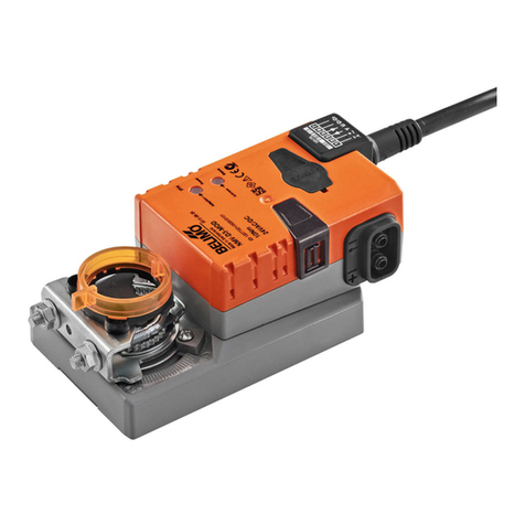
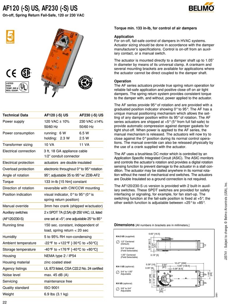
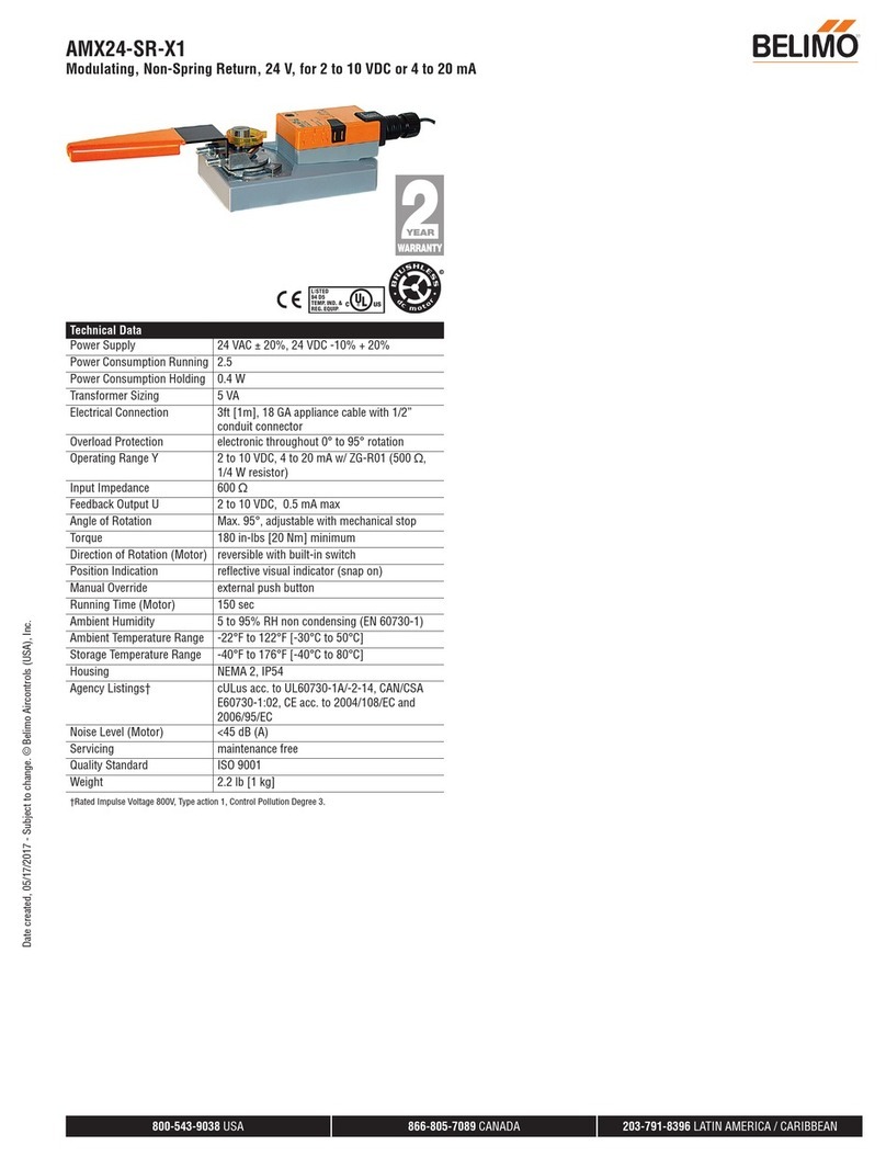
Belimo AF24-LIN US User manual

AF24-LIN US Damper Linearizing Actuator
Damper actuator, Spring Return, 24 VAC/DC power, 2 to 10 VDC and 4 to 20 mA control signal.
Output signal of 2 to 10 VDC for position indication. Programmable rotation with respect to control signal.
I20652 - 04/-06 - Subject to change. © Belimo Aircontrols (USA), INC.
1.97"
3.15" [80]
3.86" [98] 3.10" [78]
2.24"
[57]
[50]
1.93"
[49]
2.64"
[67] 0.26" [6.5]
5.85" [148.5]
10.59" [269]
0.35" [9]
0.39" [10]
0.65" [16.5]
0.19" [5]
Standard:
1/2" to 1.05"
Optional*
3/8" to 3/4"
3/8" to 5/8"
*with K4 US
clamp
®
70635-00001
Torque min. 133 in-lb, for control of air dampers
Application
For proportional modulation of dampers where linear air flow
response with respect to input signal is required..
The concept of the linearizing actuator is based on the need
recognized in problem applications where the non-linearities of
dampers themselves, linkages or jackshafts, or other geomet-
ric effects cause severe modification of flow response.
The actuator operates in response to a 2 to 10 VDC, or with
the addition of a 500Ωresistor, a 4 to 20 mA control input
from an electronic controller or positioner. A 2 to 10 VDC
feedback signal is provided for position indication or master-
slave applications.
Operation
The AF24-LIN US series actuators provide true spring return
operation for reliable fail-safe application and positive close-off
on control dampers.The spring return system provides con-
stant torque to the damper with, and without, power applied to
the actuator.
The AF24-LIN US series provides 95° of rotation and is pro-
vided with a graduated position indicator showing 0 to 90°.
The AF24-LIN US has a manual positioning crank arm which
allows the setting of any damper position within its 95° of rota-
tion.
The actuator manual override allows pre-load to provide auto-
matic compression against damper gaskets for tight shut-off.
When power is applied, the manual mechanism is released
and the actuator drives toward the full fail-safe position. The
actuator will memorize the angle where it stops rotating and
use this point for its zero position for its normal control opera-
tions. The manual override can also be released physically by
the use of a crank supplied with the actuator.
The AF24-LIN US uses a brushless DC motor which is con-
trolled by a microprocessor. The actuator may be stalled any-
where in its normal rotation without damage.
The actuator is programmed using ZIP-RS232 hardware and
the laptop software embedded within an Excel® program. The
damper manufacturer provides a chart with the signal versus
required rotation that provides a linear air flow response with
respect to the signal. Alternately the TAB and control contrac-
tor can field adjust the program.
Dimensions [All numbers in brackets are in millimeters.]
Technical Data AF24-LIN US
Power supply 24 VAC ± 20% 50/60 Hz
24 VDC ± 10%
Power consumption running: 6 W ; holding: 2.5 W
Transformer sizing 10 VA (class 2 power source)
Electrical connection
Motor 3 ft, 18 GA 4 color leads (24V)
Auxiliary switches 3 ft, 18 GA appliance cable
1/2” conduit connector
Overload protection Electronic throughout 0 to 95° rotation
Operating rangeY 2to10VDC,4to20mA
Input impedance 100 kΩ(0.1 mA), 500Ωfor 4-20 mA
Feedback output U 2 to 10VDC (max.0.5 mA) for 95°
Angle of rotation Mechanically limited to 95°
Torque 133 in-lb [15 Nm] constant
Direction of rotation Spring return reversible with CW/CCW
mounting. The control direction switch
can be used to change the action from
direct to reverse.
Position indication Visual indicator, 0° to 90° (0° is default
spring return position)
Manual override 3mm hex crank (shipped w/actuator)
Running time 150 sec. constant, independent of load,
spring return 19 seconds nominal
Humidity 5 to 95% RH non-condensing
Ambient temperature -22°F to +122°F [-30°C to +50°C]
Storage temperature -40°F to +176°F [-40°C to +80°C]
Gears Permanently lubricated
Housing NEMA type 2 / IP54
Housing material Zinc coated metal
Agency listings cULus listed to UL873 and CAN/CSA C22.2
No.24, CE
Noise level Maximum 45 dB (A)
Servicing Maintenance free
Quality standard ISO 9001, 5 year Belimo warranty
Weight 6.0 lbs (2.7 kg.)
MFT options Adjustable rotation per volt signal change
D004
1

I20652 - 04/-06 - Subject to change. © Belimo Aircontrols (USA), INC.
2
AF24-LIN US Damper Linearizing Actuator
Damper actuator, Spring Return, 24 VAC/DC power, 2 to 10 VDC and 4 to 20 mA control signal.
Mechanical Accessories
All AF series accessories may be employed:
IND-AF2 Damper position indicator
K4 US Universal clamp for 3/8” to 3/4” shafts
K4-1 US Universal clamp for up to 1.05” dia. jackshafts
K4-H Universal clamp for hexshafts 3/8” to 5/8”
KH-AF Crankarm for up to 3/4” round shaft (Series 2)
KH-AF-1 Crankarm for up to 1.05” jackshaft (Series 2)
KH-AFV V-bolt kit for KH-AF and KH-AF-1
Tool-01 10 mm wrench
SGA24 Min.and/or max. positioner in NEMA 4 housing
SGF24 Min.and/or max. positioner for flush panel mounting
ZDB-AF2 Angle of rotation limiter
ZG-100 Universal mounting bracket
ZG-101 Universal mounting bracket
ZG-102 Multiple actuator mounting bracket
ZG-103 Universal mounting bracket
ZG-104 Universal mounting bracket
ZG-106 Mounting bracket for Honeywell®Mod IV replace-
ment or new crankarm type installations
ZG-107 Mounting bracket for Honeywell®Mod III or Johnson®
Series 100 replacement or new crankarm type
installations
ZG-108 Mounting bracket for Barber Colman®MA 3../4..,
Honeywell®Mod III or IV or Johnson®Series 100
replacement or new crankarm type installations
ZG-AF Crankarm adaptor kit for AF/NF
ZG-AF108 Crankarm adaptor kit for AF/NF
ZS-100 Weather shield (metal)
ZS-150 Weather shield (polycarbonate)
ZS-260 Explosion-proof housing
ZS-300 NEMA 4X housing
For an overview of how to apply the accessories, see
Belimo Mechanical Accessories and refer to the Belimo
Mounting Methods Guide.
Go to www.belimo.us or www.belimo.ca. Then click on
“AF Linearizing Actuator” section for extensive details.
Wiring diagrams
1 Common
2 + Hot
3 Y1Input, 2 to 10V
5 U Output 2 to 10V
1
1
2
3
24 VAC Transformer
Provide overload protection and disconnect as required.
Actuators may be connected in parallel. Power consumption
and input impedance must be observed.
Actuator may also be powered by 24 VDC.
4The ZG-R01 500Ω resistor converts the 4 to 20mA.
Maximum 4 actuators parrelleled on 4 to 20 mA.
5Only connect common to neg. (—) leg of control circuits.
5
3
2
4
Control Signal (+)
4 to 20 mA
(–)
Feedback Signal
(+)
2 to 10VDC
(–)
Ω
500Ω
Line
Volts
Control Signal (+)
2 to 10VDC
(–)
1 Blk Com
2 Red + Hot
3 Wht Y1Input, 2 to 10V
5 Wht U Output 2 to 10V
1
2
3
24 VAC Transformer
AF24-LIN US
AF24-LIN US
Line
Volts
1
2
3
1
2
3
Provide overload protection and disconnect as required.
Actuators may be connected in parallel. Power consumption and input impedance must be observed.
Actuator may also be powered by 24 VDC.
4
4
5
The ZG-R01 500 resistor converts the 4 to 20 mA. Maximum 4 actuators paralleled on 4 to 20 mA.
Control Signal (+)
2 to 10VDC
(–)
1
2
3
5
1
1
2
3
24 VAC Transformer
AF24-LIN US
1
2
3
5
2
22
AF24-SR/MFT
Line
Volts
Control Signal (+)
4 to 20 mA
(–)
1
2
3
24 VAC Transformer
AF24-LIN US AF24-LIN US
Line
Volts
Mechanically paralleled actuators must be wired 5 to 3.
Electrically paralleled actuators may be wired 3 to 3 or 5 to 3.
Ω
500Ω
5
5
3
Specifications
Dampers on AH units…(name)…shall be linearized using Belimo
AF24-LIN US actuators. The control signal shall be 2-10V or 4-
20mA. Balancer shall confirm that the air flow quantity does not vary
more than ± 10% from linear with respect to the control signal.
Contractor shall provide damper manufacturer or Belimo with the fol-
lowing information:
(1) Closest AMCA figure number representing the geometry of
the installation.
(2) Damper type - Opposed Blade or Parallel Blade and presence
of jackshaft or linkage if any.
(3) Approximate authority of each damper.
Actuators shall be programmed for linearization of the damper by the
damper manufacturer or the contractor in the field as appropriate.
Safety Note
Screw a conduit fitting into the actuator’s metal bushing. Jacket the
actuator’s input and output wiring with suitable flexible conduit.
Properly terminate the conduit in a suitable junction box.
Go to to www.belimo.us or www.belimo.ca. Then click on “AF
Linearizing Actuator”for laptop program, tutorial, and other files.
W441
W442
®
Mechanically paralleled - piggyback (5 to 3)
and Electrically paralleled (3 to 3).

I20652 - 04/-06 - Subject to change. © Belimo Aircontrols (USA), INC.
3
Default Program
The feedback is set to allow slave actuators to follow accurate-
ly. It is for this reason that the feedback is 30%. If a standard
2-10V slave actuator is driven from wire 5, then that actuator
will position at the 4.5V position as calculated already.
In other words, a standard 2-10V actuator may be paralleled
with a LIN actuator if wire 5 is used to control the standard
actuator. If paralleling LIN actuators, wire 3 should be used as
input for both.
The default program outputs 8.6V at 100% open. (That is
(.94 x 8V) + 2V This AMCA application produces 100% flow
at 85% open, that is .85 x 90º. (See files.) 85º/95º= 94%.
The readings will vary slightly. For example, assume the LIN
master actuator is full closed at 0ºand the slave actuator is
full closed at -5º. In that case, the damper will position cor-
rectly for the flow, but the LIN actuator will be 80ºopen per
the indicator while the slave is 75ºaccording to the indicator.
Mechanically paralleled actuators.
While electrically paralleled actuators may be wired Signal to
3 to 3 to 3, etc., mechanically paralleled (“piggyback”) actua-
tors must be wired using Signal to 3, 5 to 3 to 3 to 3 (maxi-
mum 4 actuators). See Figure on page 1.
When the signal to a LIN increases and the actuator does not
move due to mechanical load, the wire 5 stops being a feed-
back after a few seconds. It then increases the voltage on wire
5 above the signal input for a few seconds.The follower actua-
tor then starts to move and the actuators track together.This
algorithm has been used for years by Belimo and works well.
Adaptation.
The LIN actuators do not adapt at startup or upon power inter-
ruption. If one needs the actuator to adapt, then rotate the
crank winder two times. The actuator will drive closed, then
drive to the full open position (typically limited by the damper
or linkage geometry), and then drives to the control signal
position.
The actuator will not adapt to be more open than the program
indicates.
For example, if the damper is limited to 80 degrees open and
the actuator is adapted, then 100% signal input (10V) will
cause the actuator to drive 80 degrees open. This changes
the actuator's position calculation for other points also.
If 6V (50% signal, 32% rotation) is applied, the actuator drives
.32 x 80º= 26º.That damper angle would produce 50% of
maximum airflow. Program adjustment would likely be needed.
The actuator has a default program as below. 5% refers to
the damper authority.
Actuator Functionality
Initial startup.
Upon powerup, the AF24-LIN US will drive back and find the
true damper 0 position. It sets the 0% (2V or 4mA) signal
position here.When the signal is increased beyond 2V, the
actuator drives to the programmed position for that signal
input. For example, if the signal is 6V, which is 50% in the pro-
gram, and the default program is active, then the actuator will
drive to 32% open. See the AMCA 5.2 OB 5% chart above.
In an AMCA 5.2 OB 5% Authority application, 32% open will
produce approximately 50% flow through the damper.
Feedback.
Continuing the example above:
The feedback will be 32% or about 4.5V when the signal input
is 6V or 50%. That is (.32 x 8V) + 2V.
For approximation in degrees, use 32% = .32 times 90º= 29º.
Instruments and actuators vary slightly, approximate accuracy
is sufficient.
®
AMCA 5.2 OB
damper authority 5%
Input Input Rotation Angle
Signal [V] Signal [%] [% of 95°]
20% 0%
312.5% 7%
425.0% 15%
537.5% 21%
650.0% 32%
762.5% 43%
875.0% 53%
987.5% 67%
10 100% 94%
Note that the rotation angle of the default linearization curve is
based on a 0 to 95°range, so 0% equals 0°, 100% equals 95°.

I20652 - 04/-06 - Subject to change. © Belimo Aircontrols (USA), INC.
Technical Data ZIP-RS232 US
Supply Voltage 24 VAC; Class II power supply
Power Consumption 1 W / 1.5 VA (without actuator)
Electrical protection MFT-XFMR is internally protected and
automatically resets
Connections Power supply; Stereo connector
Actuator; manual push button terminals
MP-Bus; Orange male connector, part
number ZKS-MP (Optional)
RS232; PC cable, sub-D, 9 pin,
female/female, included
Operating temperature 0°to +122°F
Storage temperature -40°F to +176°F
Electrical safety Class III
Weight <1.0 lb. (without actuator)
ZIP-RS232 US
For interfacing PC with…MFT US type actuators
®
Power supply
The MFT-XFMR accessory transformer is connected to the
unit, and supplies 24 VAC power to the ZIP-RS232 and up to
one connected actuator. The actuator on switch powers the
actuator. Separate actuator 24V may also be used.
RS232 connector
The ZIP-RS232 is connected via this RS232 connector to the PC
with a standard female-female 9-pin sub-D cable, provided.
LEDS
A Green LED is lit when 24 VAC is supplied.
Tx: LED flashes when data flows from ZIP-RS232 to actuator.
Rx: LED flashes when data flows from actuator to ZIP-RS232.
EN: LED is lit constantly when RS232 device is connected.
Accessories
Null modem serial cables can be used by switching the
ZIP-RS232 internal jumpers.
System Transformer Powered
1
2
3
5
Common
+ Hot
Control signal“Y”
U5 Diagnostics
…MFT US
RS232
D-Sub
RS232
D-Sub
ZIP-RS232
Actuator
ON
OFF 12 5
PC
24 VAC
_
T
+
~
_
T
+
~
UPP
Tx Rx EN
MP-BusSupply U5PP EN
T
24VAC/DC
50/60 Hz
1.5VA 1W
MFT-XFMR
Optional wiring via 24V
Class 2 transformer
Line voltage
Com
Hot
Standard jumper
setting Jumper setting for
null-modem cable
RS232
D-Sub
RS232
D-Sub
RS 232
ZIP-RS232
Actuator
ON
OFF
12 5
_
T
+
~
_
T
+
~
_
T
+
~
U
PP
1235
U
PP
MFT
AC 24V
DC 24V
!
Connect via
safety isolating
transformer.
Programming.
The LIN actuators do not have MFT program capacity.
The signal input is always 2-10V or 4-20mA.
Adjustable rotation with respect to signal programming.
Go to to www.belimo.us or www.belimo.ca. Then click on “AF
Linearizing Actuator”for laptop program, tutorial, and other files.
MFT-XFRM Powered
4
Other Belimo Controllers manuals
Belimo
Belimo SY-3-T-TS Series Quick start guide
Belimo
Belimo LF-2 Series User manual
Belimo
Belimo AFX24LON User manual
Belimo
Belimo AFRB24-SR Manual
Belimo
Belimo PR User manual
Belimo
Belimo LMQB24-1 User manual

Belimo
Belimo NMQB24-MFT User manual
Belimo
Belimo LRB24-3 User manual
Belimo
Belimo FS Series Use and care manual

Belimo
Belimo AF24-SR US Parts list manual
Belimo
Belimo NF24A-SR-S2 Instruction Manual
Belimo
Belimo GM24 US User manual
Belimo
Belimo NM24A-MP Instruction Manual
Belimo
Belimo LonWorks NMX24-LON User manual
Belimo
Belimo TR24-SR User manual
Belimo
Belimo LMB series User manual

Belimo
Belimo NMB24-SR User manual
Belimo
Belimo CQB24-3 User manual
Belimo
Belimo AMB24-SR-X1 User manual

Belimo
Belimo TFC120-S US User manual
