Sungrow COM100 User manual

CCOOMM110000CCoommmmuunniiccaattiioonn BBooxxUUsseerr
MMaannuuaallCCOOMM110000--VV2222--UUEENN--
VVeerr1111--220022000033
COM100-V22-UEN-Ver11-202003
COM100
CCoommmmuunniiccaattiioonn BBooxx
UUsseerr MMaannuuaall


I
CCoonntteennttss
1 About this Manual ....................................................................................... 1
1.1 Intended Use................................................................................................ 1
1.2 Target Group................................................................................................ 1
1.3 How to Use This Manual............................................................................... 1
1.4 Symbol Explanation...................................................................................... 1
2 Function Description .................................................................................. 3
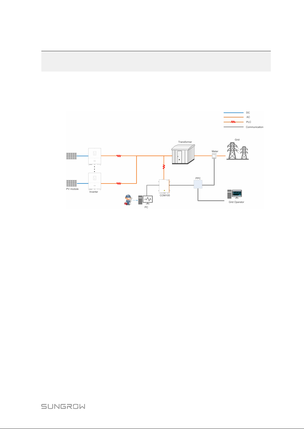
2.1 Function Introduction ................................................................................... 3
2.2 Main Features.............................................................................................. 3
2.3 Dimensions.................................................................................................. 3
3 Mechanical Installation .............................................................................. 5
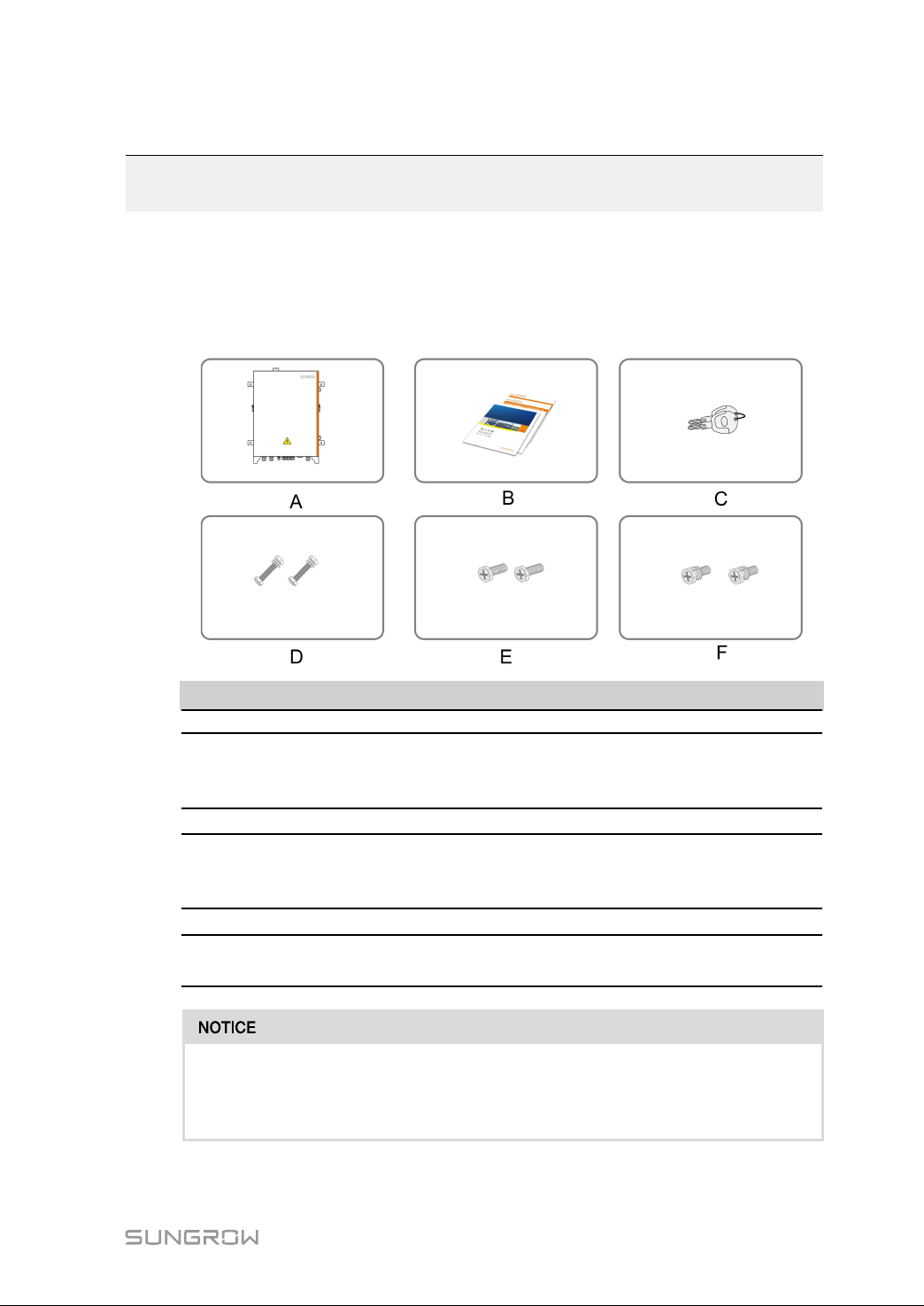
3.1 Inspection before Installation ........................................................................ 5
3.2 Location Requirements ................................................................................ 6
3.3 Installation Method....................................................................................... 6
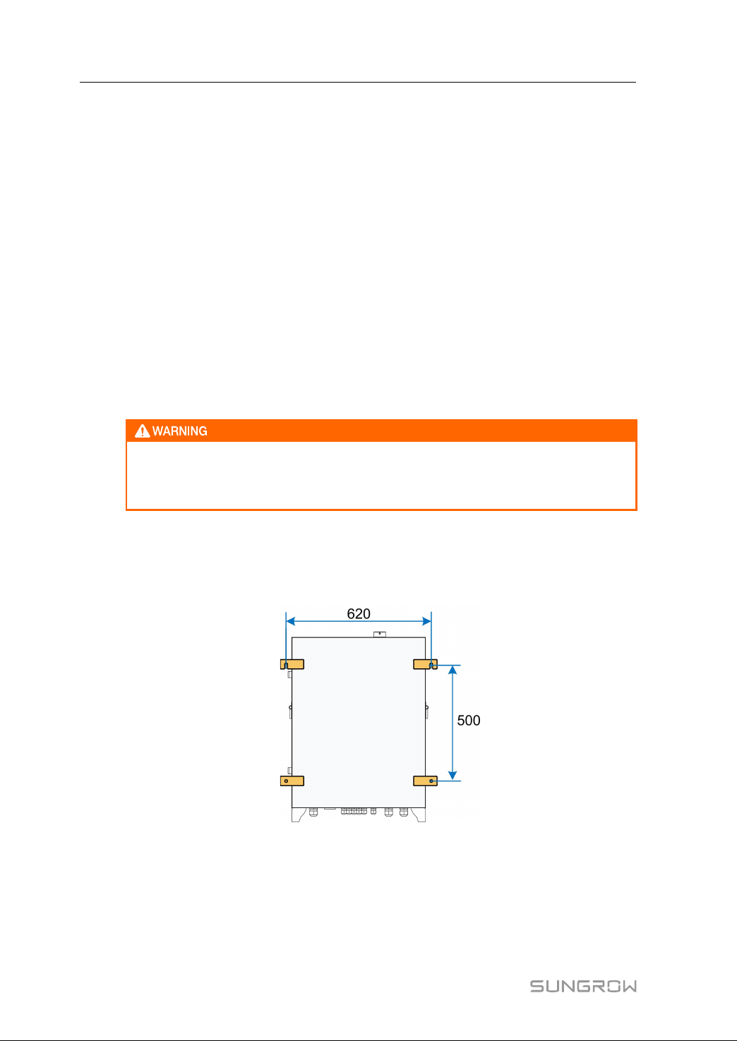
3.3.1 Wall Mounting .................................................................................... 6
3.3.2 Ground Mounting ............................................................................... 7
3.3.3 Pole Mounting (optional)..................................................................... 8
4 Electrical Connection ............................................................................... 10
4.1 Waterproof Terminal Description ................................................................ 10
4.2 Internal Structure........................................................................................ 10
4.3 Preparation Before Connection................................................................... 12
4.4 Electrical Connection Steps........................................................................ 13
4.4.1 Grounding ........................................................................................ 13
4.4.2 RS485 Communication Terminal Connection .................................... 15
4.4.3 Optical Fibre (Optional) ..................................................................... 16
4.4.4 AC 220V Connection ........................................................................ 16
4.4.5 PLC Port Connection ........................................................................ 17
4.5 Communication Methods ........................................................................... 21
5 Commissioning ........................................................................................... 22
5.1 Inspection before Commissioning............................................................... 22
5.2 Commissioning Steps................................................................................. 22

II
6 Troubleshooting ......................................................................................... 24
7 Appendix A: Related Parameters ......................................................... 25
8 Appendix B: General Information ......................................................... 26
8.1 Quality Guarantee ...................................................................................... 26
8.2 Contact Information ................................................................................... 26

1
1 About this Manual
This manual is valid for the communication box COM100 developed and manufactured
by Sungrow Power Supply Co., Ltd.
The communication box COM100 is referred to as "COM100" for short unless otherwise
specified.
1.1 Intended Use
This manual is intended to provide the reader with detailed information and description
of the installation and operation about COM100.
1.2 Target Group
This manual is intended for technically qualified persons who need to install and operate
COM100.
1.3 How to Use This Manual
Read this manual carefully before performing operation on the device. Keep the manual
in a convenient place for future reference.
All rights reserved including the pictures, symbols, and markings used in this manual.
Any reproduction or disclosure, even partially, of the contents of this manual is strictly
prohibited without prior written authorization of Sungrow.
The content of the manual will be periodically updated or revised as per the product
development. It is probably that there are changes in manuals for the subsequent
module edition. If there any inconsistency, the actual product shall govern.
1.4 Symbol Explanation
This manual contains important safety and operational instructions that must be
accurately understood and respected during the installation and maintenance of the
equipment.
To ensure the optimum use of this manual, note the following explanations of the
symbols used.
DANGER indicates a hazard with a high level of risk which, if not avoided, will
result in death or serious injury.

2
WARNING indicates a hazard with a medium level of risk which, if not avoided,
could result in death or serious injury.
CAUTION indicates a hazard with a low level of risk which, if not avoided, could
result in minor or moderate injury.
NOTICE indicates a situation which, if not avoided, could result in equipment or
property damage.
NOTE indicates additional information, emphasized contents or tips to help
you solve problems or save time.
1 About this Manual User Manual

3
2Function Description
2.1 Function Introduction
The system block diagram is shown in the following figure.
2.2 Main Features
SSmmaarrtt aanndd fflleexxiibbllee
•Integrating fiber switch and splice box, easy and flexible networking
•Integrating data collector, support of local intelligent commissioning
•Wall mounting, pole mounting, and ground mounting available, flexible installation
SSiimmppllee aanndd eeffffiicciieenntt
•Seamless connection to iSolarCloud, easy management of PV devices
•Built-in PLC communication, communication and management of string inverters
without cable routing
SSaaffee aanndd rreelliiaabbllee
•Equipped with electrical isolation and SPD protection, steady and reliable
communication
•Ingress of protection IP65, long-term reliable outdoor operation
2.3 Dimensions
The external dimensions of COM100 are shown in the following figure.

5
3 Mechanical Installation
3.1 Inspection before Installation
Check the scope of delivery for completeness according to the packing list. The
following items should be included:
IItteemm DDeessccrriippttiioonn SSuumm
A COM100 1
B
Documents, including certificate, warranty
card, delivery inspection report, user manual,
etc.
1
CKeys 2
D
M10 hexagon bolt assembly, used for wall-
mounted installation and floor-mounted
installation
4
EM4x25 bolt, used for fixing antenna 1
FM6x14 bolt assembly, used for fixing external
PE point 1
The device is carefully tested and inspected before delivery, but damage may
be caused during shipping. Therefore, inspect the device before installation. If
there any damage, contact the forwarding company or SUNGROW.

6
3.2 Location Requirements
•With the ingress of protection IP65, COM100 can be installed both indoors and
outdoors (more commonly).
•Ambient temperature: -25℃ to +60℃; and ambient humidity: ≤ 95%. Excessive
moisture can damage internal components.
•Take anti-moisture and anti-corrosion measures.
3.3 Installation Method
COM100 can be installed in two common manners: wall mounting and ground
mounting.
According to different user requirements, Sungrow provides the third optional
installation method: pole mounting. If necessary, specify your requirement when placing
an order.
Beware of the weight of COM100 throughout the installation process!
Tilting or falling of the device due to inappropriate processing can cause
personal injury!
3.3.1 Wall Mounting
The installation dimensions of mounting ears on the back of COM100 are shown in the
following figure.
step 1 Mark the hole locations on the installation wall according to the foregoing installation
dimensions and drill holes on the marked locations according to bolt specifications.
3 Mechanical Installation User Manual

7
step 2 Fasten the device in the order of M10 nut(A) , hanger(B), wall surface(C) and bolt(D),
where the fastening torque is 37±3N.m.
step 3 Check to ensure COM100 is firmly in place.
-- -- EEnndd
3.3.2 Ground Mounting
For the ground mounting, the device is fixed via the foundation bolts pre-embedded in
the foundation.
step 1 Construct the foundation according to the exterior dimensions of COM100.
step 2 Pre-embed the foundation bolts in the four foundation corners, where the bolts are of
M10.
User Manual 3 Mechanical Installation

8
step 3 Secure the mounting holes on bottom of COM100 to the foundation, where the
fastening torque is 37±3N.m.
-- -- EEnndd
3.3.3 Pole Mounting (optional)
COM100 supports pole mounting. If necessary, specify your requirements when placing
an order. Sungrow will design according to actual installation conditions.
Accessories supplied with COM100 include matching screw combinations, nuts,
brackets, clamps, and the like.
The installation steps are as follows:
step 1 Fasten the mounting ears of COM100 onto the brackets by using the matching screw
combinations, as shown in the figure below.
step 2 Fix the brackets and the clamps by using the nuts.
3 Mechanical Installation User Manual

10
4 Electrical Connection
4.1 Waterproof Terminal Description
IItteemm MMaarrkk DDeessccrriippttiioonn
AOptical fiber ports Waterproof terminals for optical
fibers
BGrounding waterproof terminal
C RS485 Waterproof terminals for RS485
communication cables
D* Input AC 400V/480V/540V/800V Waterproof terminal for PLC
communication cables
EInput AC220V Waterproof terminal for AC 220V
power cables
Note: The voltage level indicated by D* is for reference only. Specifically, refer
to the actual device purchased.
4.2 Internal Structure
The internal structure of COM 100 is shown in the following figure.

11
Internal components may differ as per selected product module. For details, refer to the
actually received product.
IItteemm DDeessccrriippttiioonn RReeccoommmmeennddeedd CCaabbllee
SSppeecciiffiiccaattiioonn SSoouurrccee
A
RS485
communication
terminal
2 x (0.75~1.5) mm2,
outdoor ultraviolet
protection STP
Beyond the scope of
delivery
B PLC1 terminal 4mm²~10mm²or
7~11AWG, withstanding
voltage:
Operating voltage<
800V
To gourd operating
voltage≥1,000V
Beyond the scope of
deliveryC PLC2 terminal
D220Vac power supply
terminal
Withstanding voltage ≥
315 Vac
1~1.5 mm2or
15~17AWG, outdoor
ultraviolet protection
cable
Beyond the scope of
delivery
ESplice box — —
User Manual 4 Electrical Connection

12
IItteemm DDeessccrriippttiioonn RReeccoommmmeennddeedd CCaabbllee
SSppeecciiffiiccaattiioonn SSoouurrccee
F
Troubleshooting
socket, AC 220V,
800W (Max.)
— —
GSurge protective
device 1
•Nominal voltage:
960Vac
•Nominal current: 6A
—
HSurge protective
device 2
•Nominal voltage:
385Vac
•Max. discharge
current: 20kA
—
I
Switch (For more
information, visit the
website of the
corresponding
manufacturer)
— —
JPLC module — —
K Logger — —
L Grounding terminal 4mm²~10mm²or
7~11AWG
Beyond the scope of
delivery
4.3 Preparation Before Connection
step 1 Open the cabinet. Unlock the door with the specific key, as shown in the following figure.
step 2 Open the upstream input switch of COM100, and turn the power switch inside COM100
to the "OFF" position to ensure COM100 is voltage-free.
-- -- EEnndd
4 Electrical Connection User Manual

13
4.4 Electrical Connection Steps
4.4.1 Grounding
SSaaffeettyy IInnssttrruuccttiioonnss
The grounding cable must be grounded reliably! Otherwise,
•Lethal electrical shock can be caused when fault occurs!
•The device may be damaged by lightening!
BBrriieeff IInnttrroodduuccttiioonn
COM100 is designed with two grounding terminals: grounding copper bar inside the
cabinet and external PE point.
On site, connect both grounding terminals reliably.
PPrreeppaarraattiioonn bbeeffoorree IInnssttaallllaattiioonn
•Prepare the grounding cable.
•Strip the cable and crimp the OT terminal.
4.4.1.1 Cooper Bar Grounding
PPoossiittiioonn DDeessccrriippttiioonn
The grounding copper bar is located inside COM100, as shown in the figure below.
User Manual 4 Electrical Connection

14
WWiirriinngg SStteeppss
step 1 Unscrew the waterproof terminal “ ” at the bottom of COM100.
step 2 Connect the yellow-green grounding cable led from outside to the grounding copper
bar inside COM100 through the internal waterproof terminal “ ”.
IItteemm DDeeffiinniittiioonn RReemmaarrkk
AM6 bolt assembly It has been installed on the copper bar before
delivery.
B OT terminal -
CGrounding hole -
step 3 Secure the cable with M6 bolt, where the fastening torque is 7.5±0.5N·m.
step 4 Screw the waterproof terminal at the bottom of COM100.
-- -- EEnndd
4.4.1.2 PE Point Grounding
PPoossiittiioonn DDeessccrriippttiioonn
The external PE point of COM100 is shown by A in the figure below.
4 Electrical Connection User Manual

15
WWiirriinngg SStteeppss
Anchor the prepared OT terminal to the grounding hole with M6 x 14 bolt assembly,
where the fastening torque is 7.5±0.5N·m.
IItteemm DDeeffiinniittiioonn RReemmaarrkk
A M6 x 14 bolt
assembly
Included in the scope of delivery
BOT terminal<-
C Grounding hole -
4.4.2 RS485 Communication Terminal Connection
CCaabbllee RReeqquuiirreemmeennttss
Cables connected to COM100 must be 2 x (0.75–1.5) mm2in cross-sectional area.
WWiirriinngg SStteeppss
step 1 Unscrew the "RS485" waterproof terminal at the bottom of COM100.
step 2 Connect the RS485 cable led from outside to the communication terminal inside
COM100 through the "RS485" communication terminal.
step 3 Strip the cable jacket with a wire stripper.
step 4 Connect the cable to corresponding terminal, and secure it with a screwdriver, where
the fastening torque ranges between 0.5N·m and 0.6N·m.
User Manual 4 Electrical Connection

16
table 4-1 Terminal definition
MMaarrkk DDeeffiinniittiioonn
GND Connected to RS485 cable shield
A Connected to RS485–A, corresponding to upper-layer terminal
BConnected to RS485–B, corresponding to lower-layer terminal
step 5 Gently pull the cable backwards to ensure firm connection.
step 6 Screw the "RS485" waterproof terminal at the bottom of COM100.
-- -- EEnndd
4.4.3 Optical Fibre (Optional)
PPrreeppaarraattiioonn bbeeffoorree IInnssttaallllaattiioonn
Before installation, prepare the required components. Components listed below are for
reference only, and the actual situation may differ.
NNoo.. CCoommppoonneenntt
1Pigtail: 12-input single-mode ST, 600mm
2Jumper: Single-mode single-core ST-SC, 500mm
3ST flange
4 Network cable, 2,600mm
IInnssttaallllaattiioonn SStteeppss
step 1 Unscrew the waterproof terminal "Optical fiber ports", and lead the optical fibre through
the terminal.
step 2 Splice the optical fibre inside the splice box.
For details, contact SUNGROW.
step 3 Screw the waterproof terminal "Optical fiber ports".
-- -- EEnndd
4.4.4 AC 220V Connection
PPrreeppaarraattiioonn bbeeffoorree IInnssttaallllaattiioonn
•Before wiring AC 220V power supply, turn the micro circuit breaker to OFF position.
•Prepare the AC cable.
4 Electrical Connection User Manual
Table of contents
Other Sungrow Conference System manuals