SUNKET-ESS LFP5000 User manual

LFP 5000
LiFePO4 BATTERY
51.2V 100Ah
USER MANUAL

2
content
Safety Precautions................................................................................................................3
Preface..................................................................................................................................4
1Introduction .....................................................................................................................4
1.1 Brief Introduction.....................................................................................................4
1.2 Product Properties ..................................................................................................4
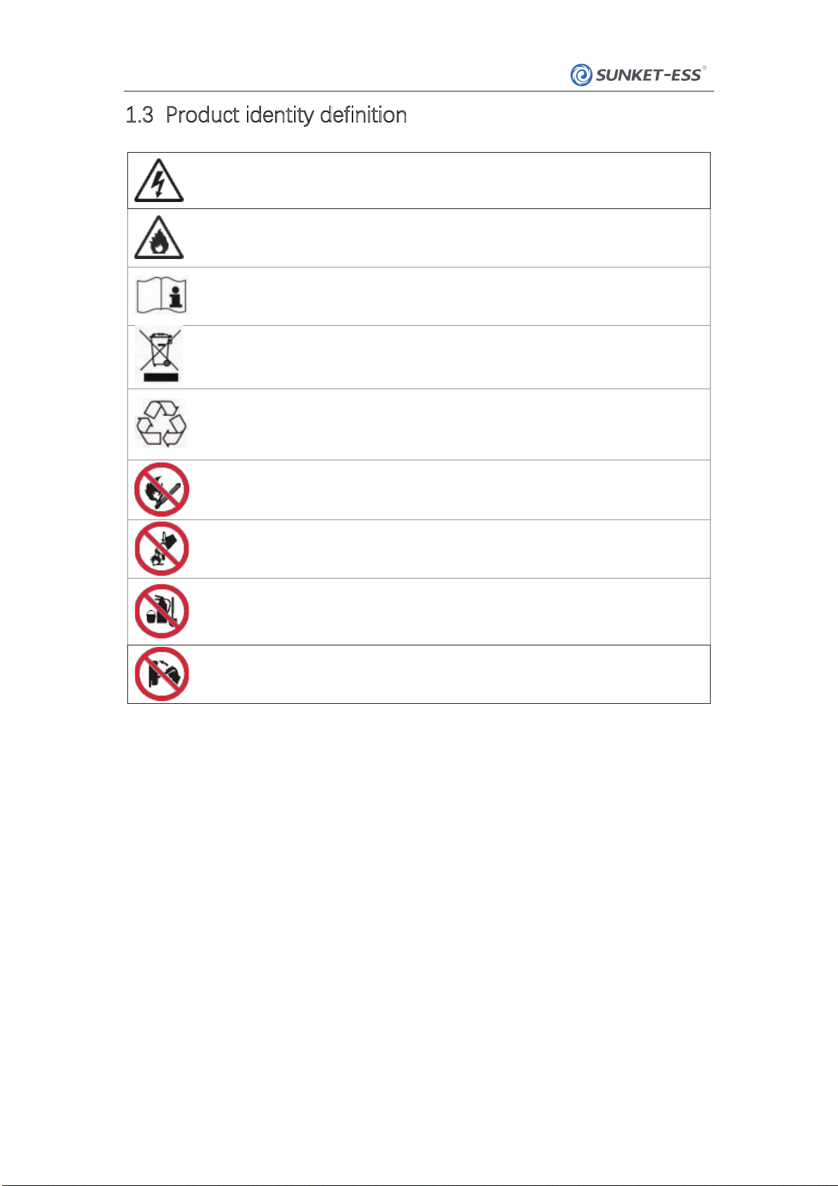
1.3 Product identity definition........................................................................................5
2 Product Specification .......................................................................................................6
2.1 Size and Weight......................................................................................................6
2.2 Performance Parameter .........................................................................................6
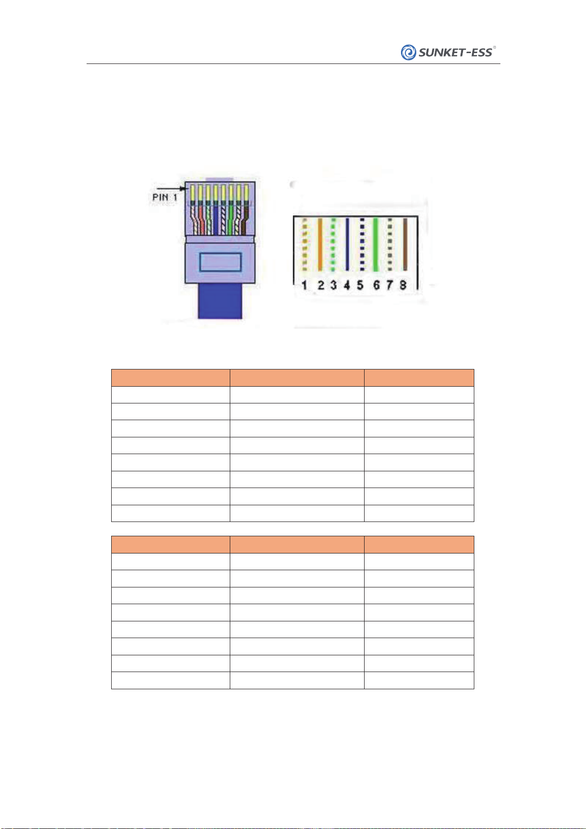
2.3 Interface Definition...................................................................................................6
2.4 Battery Management System(BMS).....................................................................
9
2.4.1 Voltage Protection .....................................................................................
9
2.4.2 Current Protection .....................................................................................
9
2.4.3 Temperature Protection ...........................................................................
10
2.4.4 Other Protection ........................................................................................
10
3 Installation and Configuration ........................................................................................
10
3.1 Preparation for installation....................................................................................
10
3.1.1 Environmental requirements ......................................................................
11
3. 1.2 Tools and data...........................................................................................
11
3.1.3 Technical preparation..................................................................................
11
3. 1.4 Unpacking inspection................................................................................
12
3. 1.5 Engineering coordination ..........................................................................
13
3.2 Equipment installation...........................................................................................
13
3.2.1 Installation preparation...............................................................................
14
3.2.2 M echanical installation ............................................................................
14
3.2.3 Electrical installation .................................................................................
14
3.2.4 Battery parameter settings on the inverter.................................................
16
4 Use, maintenance and troubleshooting.........................................................................
16
4.1 Battery system usage and operation instructions ..............................................
16
4.2 Alarm description and processing ........................................................................
17
4.3 Analysis and treatment of common faults ............................................................
18
LFP5000
..
..
..

3
Safety Precautions
Warning
Please do not put the baery into water or re, in case of explosion or any other situation
that might endanger your life.
Please connect wires properly while installation, do not reverse connect.
To avoid short circuit, please do not connect positive and negative poles with conductor on
the same device.
Please avoid any form of damage to baery, especially stab, hit, trample or strike.
Please shut othe power completely when removing the device or reconnecting wires
during the daily use or it could cause the danger of electric shock.
Please use dry powder extinguisher to put out the ame when encountering a re hazard,
liquid extinguisher could result in the risk of explosion.
For your safety, please do not arbitrarily dismantle any component in any circumstances.
The maintenance must be implemented by authorized technical personnel or our
company’s technical support. Device breakdown due to unauthorized operation will not be
covered under warranty.
Caution
Our products have been strictly inspected before shipment. Please contact us if you nd any
abnormal phenomena such as device outer case bulging.
The product shall be grounded properly before use in order to ensure your safety.
To assure the proper use please make sure parameters among the relevant device are
compatible and matched.
Please do not mixed- use baeries from dierent manufacturers, dierent types and models,
as well as old and new together.
Ambient and storage method could impact the product life span, please comply with the
operaon envi ronment instrucon to ensure device works in proper condion.
For long-term storage, the baery should be recharged once every 6 months, and the
amount of electric charge shall exceed 80% of the rated capacity.
Please charge the baery in 18 hours after it fully discharged or over-discharging protection
mode is activated.
Formula of theoretical standby time: T=C/ I (T is standby time, C is baery capacity, I is total
current of all loads).
LFP5000

4
Preface
Manual declaraon
1.2 Product Properties
LFP5000
SUNKET-ESS
LFP5000 lithium
iron
phosphate
baery
energy
storage
system
can
provide
energy storage
for
photovoltaic
power
generation
users
through
parallel
combination.
Our
product
can
store
extra
electricity
into
baery
from
photovoltaic
power
generation
system
in
daytime
and
supply stable
power
to
user’s
equipment
as
power
backup
at
nighime
or
any
time
when
needed.
It
can
improve
the
eiciency
of
photovoltaic
power
generation
and
increase
the
electric
power eiciency
by
peak
load
shiing.
This
user
manual
details
the
basic
structure,
parameters,
basic
procedures
and
mthods
of installation
and
operation
and
maintenance
of
the
equipment.
1
Introduction
1.1
Brief
Introduction
LFP5000
lithium
iron
phosphate
ba
ery
system
is
a
standard
baery
system
unit,
customers
can
choose
a
certain
number
ofLFP5000
according
to
their
needs,
by
connecting
parallel
to
form
a
larger
capacity
ba
ery
pack,
to
meet
the
user's
long-term
power
supply
needs.
The
product
is
especially
suitable
for
energy
storage
applications
with
high
operating
temperatures,
limited
installation
space,
long
powerbackup
time
and
long
service
life.
LFP5000
energy
storage
product’s
positive
electrode
materials
are
lithium
iron
phosphate,
baery
cells
are
managed
eectively
by
BMS
with
beer
performance,
the
system’s
features
as
below:
Comply
with
European
RoHS,
Certified
SGS,
employ
non-toxic,
non-pollution
environment-
friendly
baery.
Anode
materials
are
lithium
iron
phosphate
(Li
FePO4),
safer
with
longer
life
span.
Carries
ba
ery
management
system
with
be
er
performance,
possesses
protection
function
like
over-discharge,
over-charge,
over-current,
abnormal
temperature.
Self-management
on
charging
and
discharging,
Single
core
balancing
function.
Intelligent
design
configures
integrated
inspection
module.
Flexible
configurations
allow
paralle
l
of
multi
ba
ery
for
longer
standby
time.
Self-ventilation
with
lower
system
noise.
Less
baery
self-discharge,
then
recharging
period
can
be
up
to
10
months
during
the
storage.
No
mem ory
eect
so
that
ba
ery
can
be
charged
and
discharged
shallowly.
With
wide
range
of
temperature
for
working
envi
ronment,
-20℃
~
+55℃,
circulation
span
and
discharging
performance
are
well
under
high
temperature.
Less
volume,
lighter
weight.

5
1.3 Product identity definition
Baery voltage is higher than safe voltage, direct
contact with electric shock hazard.
inflammable.
Read the user manual before using.
The scrapped baery cannot be put into the garbage can
and must be professionally recycled.
After the baery life is terminated, the baery can
continueto be used after it recycled by the professional
recycling organization and do not discard it at will.
Do not place near open flame or incinerate.
If catch re, do not put out with water.
If catch fire, do not put out with dry powder fire
extinguisher.
Do not cut or spear with sharp objects.
LFP5000

6
Product Nominal
Voltage
Nominal
Capacity Dimension Weight
DC51.2V 100Ah 453×433×177mm
Item Parameter value
Nominal Voltage(V)
Work Voltage Range(V)
Nominal Capacity(Ah) 100
Nominal Energy(kWh)
50
58.4
2.3 Interface Definition
This section elaborates the interface functions of the front interface of the devic
Figure2-1 The sketch of interfac
LFP5000
2
Product
Specification
2.1
Size
and
Weight
Table
2-
1
LFP5000
Device
size
LFP5000 65kg
Table
2-2 LFP5000
performance
parameter
Max. Charge
Voltage
(Vdc)
Max. Charge Current (A)
Max. Discharge Current
(A) 50
5.12
43.2~56
51.2
1
23
45678910 11

7
Table 2-3 Interface Denition
Item Name Definition
1 SOC
The number of green lights shows the remaining power. Table 2-3
f
or details.
2 ALM
R
ed light flashing when an alarm occurs, red light always on
dur
ing protection status. After the condition of trigger protection i
s
relieved, it can be automatically
3 RUN
G
reen light flashing during standby and charging mode. Green
light always on when disc
4
ADD
DIP switc
5
CAN
Communication cascade port, support CAN communication
6
RS485
Communication cascade port, support 485 communication
7
RS485
Communication cascade port, support 485 communication
8
Res
Reset switch
9
power
power switch
10
Positive socket
Battery output positive or parallel positive lin
11
Negative socket Battery output negative or parallel negative lin
LFP5000

8
DIP switch descripon:
When the baeries are connected in parallel, the host communicates with the slaves through
the 485 interface. The host summarizes the information of the entire baery system and
communicates with the inverter through CAN.
Figure 2-2 CAN/485 interface definition
Table 2-5
CAN Pin Definition
Foot position
Color
Denion
PIN1
Orange/white
NC
PIN2 Orange NC
PIN3
Green/white
XGND
PIN4
Blue
CAN-H
PIN5
Blue/white
CAN-L
PIN6 Green XGND
PIN7
Brown/white
NC
PIN8
Brown
NC
485 Pin Definition
Foot position
Color
Denion
PIN1
Orange/white
RS485-B
PIN2 Orange RS485-A
PIN3
Green/white
XGND
PIN4
Blue
NC
PIN5
Blue/white
NC
PIN6 Green XGND
PIN7
Brown/white
RS485-A
PIN8 Brown RS485-B
Tips: Please pay aention of the communication com definition of inverter, in order to avoid
voltage in the port to aect communication.
LFP5000

Table 2-6 LED status indicators
Baery
Status SOC LED4 LED3 LED2 LED1 ALM RUN
Shutdown /oooooo
Standby / oooooFlashing
Charging
0%<SOC≤25% oooFlashing o
25%<SOC<50% ooFlashing o
50%<SO C≤75% oFlashing o
SOC>75% Flashing o
Discharging
0%<SOC≤25% oooFlashing oFlashing
25%<SOC<50% ooFlashing oFlashing
50%<SOC≤75% oFlashing oFlashing
SOC>75% Flashing oFlashing
9
LFP5000
means
green
light
always
on
2.4
Battery
Management
System(BMS)
2.4.1
Voltage
Protection
Low
Voltage
Protecon
in
Discharging
:
When
any
ba
ery
cell
voltage
or
total
voltage
is
lower
than
the
rated
protection
value
during
discharging,
the
over-discharging
protection
is
activated.
Then
baery
system
stops
supplying
power
to
the
outside.
When
the
voltage
of
each
cell
back
to
rated
return
range,
the
protection
is
over.
Note:
Aer
the
BMS
is
turned
o
aer
discharging
and
under
-voltage
protecon,
the
buon
is
acvated
or
the
charging
is
acvated,
the
BMS
will
keep
output
voltage
for
1
minute
to
detect
the
baery
voltage
of
the
inverter,
so
it
is
not
allowed
to
dischar
ge
within
1
minute.
Over
Voltage
Protection
in
Charging:
Baery
will
stops
charging
when
total
voltage
or
any
baery
cell
voltage
reaches
the
rated
protection
value
during
charging
stage.
When
total
voltage
or
all
cell
back
to
rated
range,
the
protection
is
over.
2.4.2
Current
Protection
Over
Current
Protecon
in Charging:
When
the
charging
current
is
>
50A,
the
current
limit
protecon
mode
is
acvated.
If
the
current
does
not
drop
within
10S,
the
charging
current
will
be
limited.
It
can
be
restored
aer
60S
or
the
discharge
can
be
restored
immediately.
Over
Current
Protecon
in
Discharging:
When
the
discharging
current
is
>50A,
the
current
limit
protecon
mode
is
acvated.
If
the
current
does
not
drop
within
10S,
the
discharging
current
will
be
limited.
It
can
be
restored
aer
60S
or
the
charge
can
be
restored
immediately.

2.4.3 Temperature Protection
Low/Over temperature protecon in charging:
When baery’s temperature is beyond range of 0℃~+50℃during charging, temperature
protection is activated, device stops charging.
The protection is over when temperature back to rated working range.
Low/Over temperature protecon in discharging:
When baery’s temperature is beyond range of -20℃~+55℃during discharging, temperature
protection is activated, device stops supplying power to the outside.
The protection is over when temperature back to rated working range.
2.4.4 Other Protection
Short Circuit Protection:
When the baery is activated from the shutdown state, if a short circuit occurs, the system starts
short-circuit protection.
Self-Shutdown:
When device connects no external loads and power supply and no external communication for
over 48 hours, device will dormant standby automatically.
Caution
Baery’s maximum discharging current should be more than load’s maximum working current.
3 Installation and Configuration
3.1 Preparation for installation
Safety Requirement
This system can only be installed by personnel who have been trained in the power supply
system and have suicient knowledge of the power system.
The safety regulations and local safety regulations listed below should always be followed during
the installation.
All circuits connected to this power system with an external voltage of less than 51.2V
must meet the SELV requirements defined in the IEC60950 standard.
If operating within the power system cabinet, make sure the power system is not
charged. Baery devices should also be switched o.
Distribution cable wiring should be reasonable and has the protective measures to avoid
touching these cables while operating power equipment.
when installing the baery system, must wear the protective items below:
The isolation gloves
Safety goggles
Figure3- 1
Safety shoes
10
LFP5000

3.1.1 Environmental requirements
Working temperature: -20℃~ +50℃
Charging temperature range is 0℃~+50℃,
Discharging temperature range is -20℃~+55℃
Storage temperature: - 30℃~ +45℃
Relave humidity: 5% ~ 85% RH
Elevaon: no more than 4000m
Operating environment : Indoor installation, sites avoid the sun and no wind, no conductive dust and
corrosive gas.
And the following conditions are met :
Installation location should be away from the sea to avoid brine and high humidity
environment.
The ground for product arrangement shall be at and level.
No ammable explosive materials near the installaon site.
The optimal ambient temperature is 15℃~ 30 ℃
Keep away from dust and messy zones
3.1.2 Tools and data
Tools and meters that may be used are shown in table 3- 1.
Table 3- 1 Tool instrument
3.1.3 Technical preparation
Electrical interface check
Devices that can be connected directly to the baery can be user equipment, power supplies, or other
power supplies .
Conrm whether the user's PV power generation equipment, power supply or other power
supply equipment has a DC output interface, and measure whether the DC power output voltage
meets the voltage range requirements in Table 2-2.
Conrm that the maximum discharge current capability of the DC power interface of the user's
photovoltaic power generation equipment, power supply or other power supply equipment
should be higher than the maximum charging current of the products used in Table 2-2.
If the maximum discharge capacity of the DC power interface of the user's photovoltaic power
generation equipment is less than the maximum charging current of the products used in Table 2-
2, the DC power interface of the user's photovoltaic power generation equipment shall have a
current limiting function to ensure the normal operation of the user’s equipment.
Verify that the maximum operating current of the baery-powered user equipment (inverter
DC input) should be less than the maximum discharge current of the products used in Table 2-2.
The security check
Firefighting equipm ent should be provided near the product, such as portable dry powder
fire extinguisher.
Automatic fire fighting system shall be provided for the case where necessary.
No flammable, explosive and other dangerous materials are placed beside the baery.
Name
Screwdriver(Slotted、Phillips)
Multimeter
Torque wrench
Clamp current met
Diagonal pliers
Insulation tape
Pointed nose plie
Temperature meter
Pliers to hold the wire
Anti-static bracele
Stripping pliers
Cable tie
Electric dril
Tape measur
11
LFP5000

3.1.4 Unpacking inspection
When the equipment arrives at the installation site, loading and unloading should be carried
out according to the rules and regulations, to prevent from being exposed to sun and rain.
Before unpacking, the total number of packages shall be indicated according to the
list aached to each package, and the case shall be checked for good condition.
shipping
In the process of unpacking, handle with care and protect the surface coating of the object.
Open the package, the installation personnel should read the technical documents, verify the list,
according to the configuration table and packing list, ensure objects are complete and intact, if the
internal packing is damaged, should be examined and recorded in detail
Packing list is as follows:
Item Specication Quanty Figure
SKT-48100P 51.2V/ 100Ah
1
Parallel cable-
posve
Red
/25mm2/ L250mm
1
Parallel cable-
negave
Black
/25mm2/ L250mm
1
Communicaon
parallel cable
Black
/ L500mm/ Double
RJ45 plug
1
Ground wire
L500mm,4mm²
1
User Manual
User manual
1
12
LFP5000

3.1.5 Engineering coordination
Attention should be paid to the follow ing item s before construction:
Power line specification.
The power line specification shall meet the requirements of maximum discharge current
for each product.
Mounting space and bearing capacity.
Make sure thatthe battery hasenough roomto install, and that the brackets have
enough load capacity.
Wiring.
Make sure the power line and ground wire are reasonable. Not easy toshort-circuit,
water and corrosion.
3.2 Equipment installation
Table 3-2 Installation steps
Step1 Installation
preparation
Step 2Mechanical
installation
1. Battery placement position determination
2Battery module installation
Step3 Electrical
installation
1. Ground cable installation
2. Battery module parallel cable installation
3 . Parallel communication cable connection
Step4 Battery system
self-test
1. Turn the ON/O FF sw itc h to the "ON" state
2. Press SW button 3 S to w ake up battery
3. Check the system output voltage and led status
4. Shut dow n the sys tem
Step5
Connecting
inverter
1. Connect total positive & total negative cable of the
battery system to the inverter
2Battery m odule total positive cable installation
3. Battery module total negative cable installation
4. Connect the communication cable from the m aster CAN
IN to the inverter
5.Turn on the Pow er sw itch and w ake up system by SW
button
6 C lo se the D C b reaker b etw een i nv erter a nd ba ttery
7.Turn on the inverter and check the communication
between inverter and battery system
13
LFP5000
Confirm
that
the
ON/OFF
switch
on
the
front
panel
of
LFP5000
unit
is
in
the
“OFF”
state
to
ensure
no
live
operation.

3.2.1 Installation preparation
1. Prepare to install equipment and tools to detect if the battery is off.
2. Confirm the form of the battery. The two forms can be switched as required, as shown in
Figure 3-1, and can be used in a matching cabinet, as shown in Figure 3-2, which can be
directly stacked. (Picture 3-2 bracket needs to be purchased additionally)
3.2.3 Electrical installation
Before connecting the power cables, use multimeter to measure cable continuity, short circuit, confirm
positive and negative, and accurately mark the cable labels.
Measuri ng methods:
Power cable check : select the buzzer mode of multimeter and detect the both ends of the same
color cable. If the buzzer calls, it means the cable is in good condition.
Short circuit judgment : choose multimeter resistor file, probe the same end of positive and
negative pole, if the resistor shows infinity, means that the cable is available.
After visual testing of power line connection,the positive and negative poles of the battery
shall be connected respectively to the positive and negative poles of the opposite terminal.
It is better to add a circuit breaker between the inverter and the battery system. The selection of the
circuit breaker requires:Voltage:>60V, current:I=Inverter power/51.2V.
figure3-3.
figure3-1.
figure3-2.
14
LFP5000
3.2.2
M
echanical installation
1.
Place the
LFP5000, as shown in Figure 3-3,
align the upper and lower mounting ears holes,
and
then
assemble
by
the
combination
of
bolts
-
spring washers
-
flat washers
-
mounting ears
-
nuts.
A total of 8 sets of corners need to be assembled.

Communication
cable-to inverter
Figure3- 4
Note:
1. For more ADD Settings ,Reference 2.3. 1 “DIP switch definition and description”
2. After the whole system connection, set the master DIP mode according to the inverter model firstly,
then start the battery.
3. The BAT- INV comms cable is from inverter comm port to master CAN IN port, BAT- BAT cable is from
master CAN OUT to slave1 CAN IN, slave1 CAN OUT to slave2 CAN IN …
4. Each pair of power cable, it’s limited continuous current is 120A, so if the inverter Max. work current
more than 120A, please add power cable according to the proportion.
Communication
parallel cable
parallel cable-
negative
Parallel cable-
positive
Power cable-
negative
Power cable-
positive
15
LFP5000

3.2.4 Battery parameter settings on the inverter
Max Charging(Bulk) Voltage: 58.4V
Absorption Voltage: 56.8V
Float Voltage: 54V
Shut Down(cut off) Voltage: 50V
Shut Down(cut off) SOC: 15%
Max Charge Current : 50A*battery QTY
Max Discharge Current : 50A*battery QTY
4 Use, maintenance and troubleshooting
4.1 Battery system usage and operation instructions
After completing the electrical installation, follow these steps to start the battery system.
1. Refer to the description of the DIP switch of 2.3.1 to prepare the battery module before
starting up, then press the ON/OFF button to the ON position, press and hold the SW
button for 3 seconds.
2. After the indicator self-test, the RUN indicator will light and the SOC indicator will be on
(100% SOC status in the Figure4- 1).
Figure4-
1
16
LFP5000
ALM PUM ADD CAN/232 RS485 IN/OUT RES POWER

Caution:
1. After pressing the power button,if the battery status indicator on the frontpanel
continues to be red, please refer to the "4.2 Alarm description and processing ". If the
failure cannotbe eliminated,please contact the dealer timely.
2. Use avoltmeter to measure whether the voltage of the circuit breaker battery access
terminal is higher than 48V, and check whether the voltage polarity is consistent with
the inverter inputpolarity. If the circuit breakerbattery inputterminal has avoltage
outputand is greater than 48V,then the battery begun to work normally.
3. After confirming that the battery outputvoltage and polarity are correct, turn on the
inverter, close the circuit breaker.
according to Table 4- 1.
Table 4- 1 Main alarm and Protectio
Statue Alarm category Alarm indication Processing
Charge state
Over-current RED Stop charging and find out
the cause of the trouble
High temp RED Stop charging
Discharge
state
Over-current RED
Stop discharging and find
out the cause of the trouble
High temp RED Stop discharging and find
out the cause of the trouble
Total voltage
undervoltage
RED
Start charging
Cell voltage
undervoltage
RED
Start charging
17
LFP5000
4.
Check
if
the
indicator
of
the
inverter
and
battery
connection
(communication
indicator
and
battery
access
status
indicator)
is
normal.
If
it
is
normal,
successfully
complete
the
connection
between
the
battery
and
the
inverter.
If
the
indicator
light
is
abnormal,
please
refer
to
the
inverter
manual
for
the
cause
or
contact
the
dealer.
4.2
Alarm
description
and
processing
When
protection
mode
is
activated
or system
failure
occurred,
the
alarm
signal
will
be
given
through
the
working
status
indicator
on
the
front
panel
of
the
LFP5000.
The
network
management
can
query
the
specific
alarm
categories.
If the fault such as single cell over voltage, charging over
-current, under-voltage protection, high-
temp protection and other abnormalities which affects the output, please deal with it

4.3 Analysis and treatment of common faults
Analysis and treatment of common faults in the Table 4-2:
Table 4-2 Analysis and treatment of common faults
No.Fault phenomenon Reason analysis Solution
1
The indicator does
not respond after the
power on
Total voltage lower than 35VCheck the total voltage
2 No DC output
Battery data status is abnormal.
Battery gets into over-discharged
protection
Read the battery
information on the
monitor.
3 The DC power supply
time is too short Battery capacity become smaller
Storage battery
replacement or add more
modules
4 The battery can't be
fully charged to 100% Charging voltage is too low Adjust charging voltage at
57V or 57.6V
5
The power cable
sparks once power on
and ALM light RED
Power connection short-circuit
Turn off the battery, check
the cause of the short
circuit
6
Communication fault
The DIP setting of the host is
wrong/ the battery type of the
inverter is wrong/
Communication cable used
incorrectly/The communication
cable is incorrectly connected at
the battery communication port
or the inverter communication
port/The battery firmware
version is too low to support the
inverter
Check these possible
causes one by one
18
LFP5000

Other manuals for LFP5000
1
Table of contents
Other SUNKET-ESS Batteries Pack manuals