Benchmark DAC1 PRE User manual

Benchmark DAC1 PRE
Instruction Manual
2-Channel 24-bit 192-kHz
Digital-to-Analog Audio Converter
withPreampFunctionsandUSBInput

DAC1 PRE Instruction Manual Rev J Page 2
Safety Information
Voltage Selection
CAUTION: THE FUSE DRAWER INCLUDES
A VOLTAGE SELECTION SWITCH WITH
TWO SETTINGS: ‘110’AND ‘220’. CHECK
TO SEE THAT IT IS PROPERLY
CONFIGURED FOR YOUR LOCATION
BEFORE CONNECTING AC POWER.
Incorrect configuration may blow fuses or
cause erratic operation.
Repairs
CAUTION: DO NOT SERVICE OR REPAIR
THIS PRODUCT UNLESS PROPERLY
QUALIFIED. ONLY A QUALIFIED
TECHNICIAN SHOULD PERFORM
REPAIRS.
Fuses
CAUTION: FOR CONTINUED FIRE
HAZARD PROTECTION ALWAYS REPLACE
THE FUSES WITH THE CORRECT SIZE
AND TYPE (0.5A 250 V SLO-BLO® 5 X 20
MM –LITTELFUSE® HXP218.500 OR
EQUIVALENT).
Modifications
CAUTION: DO NOT SUBSTITUTE PARTS
OR MAKE ANY MODIFICATIONS
WITHOUT THE WRITTEN APPROVAL OF
BENCHMARK MEDIA SYSTEMS, INC.
MODIFICATION MAY CREATE SAFETY
HAZARDS AND VOID THE WARRANTY.
NOTICE: CHANGES OR MODIFICATIONS
NOT EXPRESSLY APPROVED BY
BENCHMARK MEDIA SYSTEMS COULD
VOID THE USER'S AUTHORITY TO
OPERATE THE EQUIPMENT UNDER FCC
REGULATIONS.

DAC1 PRE Instruction Manual Rev J Page 3
Contents
Safety Information 2
Voltage Selection 2
Repairs 2
Fuses 2
Modifications 2
Contents 3
Features 4
Overview 5
DAC1 and DAC1 USB Heritage 5
Applications 5
AdvancedUSB Audio™ Technology 5
Jitter-Immune UltraLock™5
HPA2™ Headphone Amplifier 6
High-Current Output Drivers 6
‘Audio-Always’ Design Philosophy 6
Low-Noise Internal Power Supply 6
Phase-Accurate Multi-Track and 5.1 6
Automatic Digital De-Emphasis 6
Quick Start Guide 7
Audio Inputs 7
Volume Control 7
Direct Interfacing to Power Amplifiers 7
Source Selector and On/OFF Switch 7
Input Status Display 7
Automatic Standby/Resume 7
Mute on Headphone Insertion 7
Front Panel 8
Input Status Display 8
Error Indication 8
“Source” and “ON/OFF” Switch 8
Standby Mode 9
HPA2TM Headphone Jacks 9
Volume Control 9
Rear Panel 10
Analog Input –RCA Unbalanced 10
Computer Input –USB 10
Digital Input 1 –Optical 11
Digital Inputs 2, 3, and 4 - Coaxial 11
Output Level Switch 12
Balanced XLR Analog Line Outputs 12
Unbalanced RCA Analog Outputs 13
Low-Impedance Passive Pads 13
Calibration Trimmers 14
AC Power-Entry and Fuse Module 14
Internal Settings 15
Removing Top Cover 15
Jumpers 15
Rack Mounting 17
System1™ Universal Rack Adapter 17
Blank Rack Panel 17
Benchmark Technologies 18
HPA2™ Headphone Amplifier 18
UltraLock™ Clock System 18
AdvancedUSB Audio™ Technology 21
Performance Graphs 24
Frequency Response Tests 24
FFT Analysis of Idle Channel Noise 26
Multi-Unit Phase Response 27
THD+N Tests 28
Jitter Tests 33
Input Sensitivity Tests 36
Volume Control Curve 38
Specifications 39
Audio Performance 39
Group Delay (Latency) 40
Analog Audio Inputs 41
Digital Audio Inputs 41
Balanced Analog Outputs 43
Unbalanced Analog Outputs 43
HPA2TM Headphone Outputs 44
Status Display 44
AC Power Requirements 45
Dimensions 45
Weight 45
Regulatory Compliance 46
FCC and RoHS Compliance Statements 46
CE Certificates of Conformity 46
CE Certificates of Conformity 47
Warranty Information 49
Benchmark 1 Year Warranty 49
Benchmark Extended Warranty 50

DAC1 PRE Instruction Manual Rev J Page 4
Features
Reference-quality 2-channel 192-kHz 24-bit digital-to-analog audio converter
“System Preamp” (control amplifier) functions include input selection and volume control
Designed to connect directly to power amplifiers and/or powered monitors and/or preamps
6 stereo inputs –1 analog (RCA), 1 computer (USB), 1 optical (TOSLINK), and 3 coaxial (RCA)
4 stereo analog outputs –balanced (XLR), unbalanced (RCA), and 2 headphone outputs
Rotary input selector switch with standby on/off function
Two reference-grade HPA2™ “0-Ohm”, high-current, ¼” headphone outputs
Front-panel volume control for headphone outputs
Front-panel volume control of all analog outputs (in Variable mode)
Rear-panel Variable/Calibrated switch selects the volume/mute mode of analog outputs
In Calibrated mode, output levels are set by 10-turn trimmers (20 dB Range, 2 dB/turn)
Benchmark’s AdvancedUSB Audio™ input supports high-resolution 96-kHz 24-bit digital audio
AdvancedUSB™ is compatible with Windows and Mac computers without driver installation
Coaxial digital inputs support professional (AES) and consumer (S/PDIF) data formats at up to
192-kHz, 24-bits
Optical digital inputs support professional (AES) and consumer (S/PDIF) data formats at up to
96-kHz, 24-bits
Benchmark’s UltraLock™ technology eliminates jitter on all digital inputs (including USB)
Jumper-selected low-impedance 10, 20, or 30 dB pads on balanced outputs
HPA2™ gain jumpers for customizing headphone output gain for headphone sensitivities
Left-most headphone jack auto-mutes XLR and RCA outputs (feature may be disabled)
Status LED’s - display input selection and error conditions
Automatic Standby Mode –activated after 15 seconds of loss of digital input signal
Instant wake-up from Standby Mode - no loss of audio
Automatic de-emphasis in response to consumer pre-emphasis bit (44.1, 48, 88.2, and 96 kHz)
115 V, 230 V, 50-60 Hz international power supply with very wide operating range
Low radiation toroidal power transformer significantly reduces hum and line related interference
Low power consumption (8 Watts typical program, 16 Watts peak)
Meets FCC Class B and CE emissions requirements

DAC1 PRE Instruction Manual Rev J Page 5
Overview
The DAC1 PRE is a reference-quality, 2-
channel 192-kHz 24-bit digital-to-analog
audio converter, stereo preamplifier, and
headphone amplifier. It features
Benchmark’s AdvancedUSB Audio™
technology, UltraLock™ clock system, and
HPA2™ headphone amplifier.
DAC1 and DAC1 USB Heritage
The pristine audio path of the award-winning
DAC1 has made it the ‘Benchmark’of stand-
alone D/A converters. The DAC1 USB and
DAC1 PRE preserve the exact topology of the
DAC1 audio path while adding some of the
most frequently requested features.
With the introduction of the DAC1 USB we
added a very unique USB input with native
96/24 capability, an auto-mute function for
headphone use, customizable headphone gain
range, an automatic standby feature, and a
high-current LM4562/LME49860 output stage
designed to drive long cables and/or difficult
loads, such as high-end power-amplifiers.
The DAC1 PRE adds the versatility of a
stereo analog input and three S/PDIF digital
inputs. National LM4562/LME49860 opamps
are used throughout, and all RCA connectors
are premium bulkhead mounted RCA
connectors for maximum durability and
superior grounding.
The DAC1 PRE looks, sounds, and measures
the same as the DAC1 and DAC1 USB. We
have added convenience and flexibility
without altering the performance or changing
the signal path.
Applications
The DAC1 PRE is designed for maximum
transparency and is well suited for critical
playback in studio control rooms, mastering
rooms, and high-end audiophile applications.
Benchmark’s AdvancedUSB Audio™
interface makes the DAC1 PRE an ideal
primary output device for digital audio
workstations, desktop audio editing
applications, computer-based media
playback, home media servers, and
computer-based radio broadcast systems.
A rugged rack-mount adapter makes the
DAC1 PRE an excellent choice for location
recording, broadcast facilities, and mobile
trucks.
AdvancedUSB Audio™ Technology
The USB input is compatible with Windows
Vista/XP/2000 and Mac OS X with no driver
installation or system configuration required
(see www.benchmarkmedia.com/wiki for up-
to-date compatibility information).
Benchmark’s AdvancedUSB Audio™
technology supports sample rates up to 96
kHz and word lengths up to 24 bits.
The DAC1 PRE is a true plug-and-play
solution, and it will be ready for playback
immediately after the unit is connected to a
USB port for the first time.
Jitter-Immune UltraLock™
The Benchmark UltraLock™ system is nearly
100% jitter-immune. The D/A conversion
clock is isolated from the input digital audio
clock in a topology that outperforms two-
stage PLL designs. In fact, no jitter-induced
artifacts can be detected using an Audio
Precision System 2 Cascade test set.
Measurement limits include detection of
artifacts as low as -140 dBFS, application of
jitter amplitudes as high as 12.75 unit
intervals (UI) and application of jitter over a
frequency range of 2 Hz to 200 kHz.
Any signal that can be decoded by the USB or
AES/EBU receivers will be reproduced without

DAC1 PRE Instruction Manual Rev J Page 6
the addition of any measurable jitter artifacts.
The AES/EBU receiver IC has been selected
for its ability to accurately recover data in the
presence of very high jitter levels.
HPA2™ Headphone Amplifier
Two ¼” headphone jacks are driven by the
HPA2™ - Benchmark’s signature high-
current, 0-Ohm headphone amplifier. The
HPA2™ is capable of delivering the full
performance of the DAC1 PRE into the
difficult loading presented by headphones.
The HPA2™ maintains less than 0.0003%
THD+N under full load.
High-Current Output Drivers
The DAC1 PRE features new high-current
output drivers that are capable of driving
300-Ohm loads without an increase in
distortion. They are also well suited for
driving long cables or high-capacitance loads.
‘Audio-Always’ Design Philosophy
The DAC1 PRE is designed to perform
gracefully in the presence of errors and
interruptions at the digital audio inputs. A
soft mute circuit eliminates pops when a
digital signal is applied. Power management
circuitry controls the muting and resetting of
all digital circuits upon removal and
application of power. Audio is present at the
outputs only 60 ms after applying, selecting,
or restoring a digital input signal and only 500
ms after applying power to the unit.
The DAC1 PRE is designed to avoid all
unnecessary mute scenarios. Muting is only
enabled upon loss of power, or when digital
transmission errors occur. The DAC1 PRE
does not mute when the AES or S/PDIF input
data is all zeros. Consequently, no audio is
lost when an audio transient follows full
silence. Furthermore, the DAC1 PRE signal-
to-noise specifications represent the true
system performance, not just the
performance of an output mute circuit.
The DAC1 PRE will operate even when
sample rate status bits are set incorrectly.
Sample rate is determined by measuring the
incoming signal. Lack of sample rate status
bits or incorrectly set status bits will not
cause loss of audio.
The DAC1 PRE includes non-volatile memory
that saves the state of control settings when
AC power is removed for a period of up to
several hours. The unit will resume normal
operation after interruptions in AC power.
Low-Noise Internal Power Supply
The internal power supply supports all
international voltages with generous margins
for over and under voltage conditions. It has
excellent immunity to noise on the AC line
and no external AC filtering is required.
Phase-Accurate Multi-Track and 5.1
The DAC1 is phase-accurate between
channels at all sample rates, and is phase
accurate between any combination of DAC1,
DAC1 USB, and DAC1 PRE converters at
sample rates up to 96 kHz. Phase-accurate
multi-track and 5.1 surround systems are
easily constructed using any combination of
DAC1 series converters.
Automatic Digital De-Emphasis
Pre-emphasis was used on many early CD
recordings. It is rarely used on newer
recordings and consequently some D/A
converters omit de-emphasis. The DAC1
PRE will correctly apply precise digital de-
emphasis when and if it is needed. The de-
emphasis circuit supports 44.1, 48, 88.2 and
96-kHz sample rates and is automatically
enabled in response to the pre-emphasis
status bits in consumer format digital signals.

DAC1 PRE Instruction Manual Rev J Page 7
Quick Start Guide
Audio Inputs
The DAC1 PRE features one stereo analog
input (RCA) and five stereo digital inputs (3 x
coaxial, 1 x optical, and 1 x USB). The coaxial
and optical digital inputs accept professional
(AES) and consumer (S/PDIF) data formats at
word lengths up to 24-bits. The coaxial inputs
support sample rates up to 192 kHz. The
optical inputs support sample rates up to 96
kHz.
Volume Control
The front-panel Volume Control sets the
output level of the headphone jacks, and can
also be used to control the output level of the
main outputs (balanced XLR and unbalanced
RCA analog) when in Variable output mode.
A rear-panel switch selects Variable or
Calibrated output mode. In Variable output
mode, all analog outputs are controlled by the
Volume Control.In Calibrated output
mode, the volume is fixed at the level set by
the calibration trim-pots.
Direct Interfacing to Power Amplifiers
The DAC1 PRE is designed to be able to
interface directly to power amps and powered
studio monitors. This configuration provides
the cleanest and shortest path from the
digital source to the monitor output, and
often results in a substantial improvement in
sound quality.
The DAC1 PRE is equipped with 10, 20, and
30 dB output attenuators for optimal
interfacing. The pads optimize the output
signal level of the DAC1 PRE for the input
sensitivity of virtually any load (amplifier,
preamp, etc). Most power amplifiers and
powered monitors require the 20 dB pad
setting. The DAC1 PRE is factory-set with
the 20 dB pad enabled.
Source Selector and On/OFF Switch
A rotary Source Selector control selects any
of the 6 inputs to the DAC1 PRE. Pressing
the Source Selector toggles the DAC1 PRE
on and off. The on/off function features a
very fast soft mute/un-mute and doubles as a
mute control.
Input Status Display
Under normal operation, the Input Status
Display shows which of the 6 inputs is
currently selected. A steady light indicates
that a normal signal is present. Flashing
lights indicate error conditions. If the error
condition continues, the automatic-standby
mode will begin.
Automatic Standby/Resume
The DAC1 PRE features an automatic
standby mode that eliminates the need to
turn the converter on and off. Standby
Mode starts 15 seconds after a digital source
device is turned off, disconnected, or contains
errors that prevent D/A conversion. All lights
are off while in Standby Mode.
While in Standby Mode, the DAC1 PRE
continues to monitor the selected digital input
and will immediately resume normal
operation when an error-free signal is
restored.
Mute on Headphone Insertion
The left-hand headphone jack includes a
switch that mutes the main analog outputs
(XLR and RCA) when a headphone plug is
inserted. This feature allows the listener to
switch from loudspeaker to headphone
playback seamlessly. This mute feature can
be disabled with internal jumpers.

DAC1 PRE Instruction Manual Rev J Page 8
Front Panel
Input Status Display
The DAC1 PRE has a six-LED input-selection
indicator on the front panel. These LED’s
flash when an error condition occurs on a
selected digital input. All LED’s turn off when
the DAC1 PRE is in Standby Mode or is
turned off.
The numbers next to the LED’s match the
numbers adjacent to the digital connectors on
the rear panel. Digital input “1” is TOSLINK
Optical. Inputs 2, 3, and 4 are RCA Coaxial.
Error Indication
The Input Status Display will flash when an
error occurs on the selected digital input. The
type of error is indicated by the number of
flashes before standby engages.
Error Codes:
No signal –16 slow flashes –audio muted
Data transmission errors - 16 flashes –
audio muted
Non-PCM –16 flashes –audio muted
Non-audio –32 rapid flashes –audio muted
Invalid sample (v-bit) –64 very rapid
flashes –no mute
Common causes of errors are:
Disconnected cable
Data drop-outs due to a bad cable
Incompatible data type (AC3, ADAT, etc.)
Non-Audio data
If the error is not resolved within +/- 15
seconds, the DAC1 PRE will enter Standby
Mode. The DAC1 PRE will resume normal
operation when it detects a valid input signal
at the last chosen input. There is no error
indication on the analog input.
“Source” and “ON/OFF”Switch
The rotary Source Selector control is located
directly to the right of the Input Status
Display. Rotate the knob to select an input.
The rotary Source Selector switch is
equipped with an on/off switch. Press the
control knob to turn the DAC1 PRE on or off.
The on/off function features a soft mute and
soft un-mute function that responds very
quickly. Because of this fast response, the
on/off function also serves as a mute control.
Press the Source Selector switch to mute all
audio outputs. Press again to restore all
audio outputs.
No analog or digital audio signals are routed
through the Source Selector switch. Source
selection is transparent and free from
crosstalk.
If the DAC1 PRE is off or in Standby Mode
it will resume normal operation when the
Source Selector is rotated or pressed.

DAC1 PRE Instruction Manual Rev J Page 9
Standby Mode
The DAC1 PRE features an automatic
standby mode that eliminates the need to
turn the converter on and off. Standby
Mode starts 15 seconds after the selected
digital source device is turned off,
disconnected, or contains errors that prevent
D/A conversion. All status LED’s are off while
in Standby Mode.
While in Standby Mode, the DAC1 PRE
continues to monitor the selected digital input
and will immediately resume normal
operation when an error-free signal is
restored.
HPA2TM Headphone Jacks
The DAC1 PRE features two headphone jacks.
The left-hand jack is equipped with a switch
that automatically mutes the XLR and RCA
analog outputs when a headphone plug is
inserted. The right-hand jack has no switch.
This feature enables seamless muting of the
main outputs when headphones are being
used. This auto-mute feature can be enabled
or disabled via an internal jumper.
Instructions for setting the auto-mute jumper
are detailed in the ‘Internal Settings’
section of this manual.
TIP: Use the left-hand jack when you
want to listen to headphones and mute
your playback system. Use the right-
hand jack when you need to keep all
outputs active.
The dual jacks also allow two listeners to
monitor and compare notes on what is heard.
When comparing, we recommend using
identical headphones because headphone
sensitivities differ significantly. The Volume
Control adjusts the level for both jacks.
The original gain-range of the HPA2™ (such
as in the original DAC1) is often too high for
the headphones of many users. The DAC1
PRE features three gain ranges for the
HPA2™ to suit the sensitivity of any
particular headphones. These gain ranges
are set using internal jumpers. The jumpers
reduce the input to the HPA2™ by 0, 10, or
20 dB. These jumpers are factory-installed at
10 dB below full gain. Instructions for setting
the headphone gain range are detailed in the
‘Internal Settings’ section of this manual.
TIP: For optimal performance, the
headphone gain jumpers should be set
so that comfortable listening levels occur
when the ‘Volume Control’is set above
the 10th detent.
Volume Control
The front-panel Volume Control is a 41-
detent potentiometer (see ‘Volume Control
Curve’ in the ‘Performance Graphs’ section of
this manual).
The Volume Control always controls the
output level of the headphone jacks. It can
also be used to control the output levels of
the balanced XLR and unbalanced RCA analog
outputs when the rear-panel Output Level
Switch is set to Variable.
The XLR outputs have jumper-enabled
passive attenuators that can be used to
optimize the gain structure of the playback
system.
TIP: For optimal performance and
minimal noise, the XLR gain jumpers
should be set so that comfortable
listening levels occur when the ‘Volume
Control’ is set above the 10th detent.
Instructions for setting the XLR pads are
detailed in the ‘Internal Settings’ section of
this manual. The DAC1 PRE is shipped with
the XLR attenuation set to -20 dB.

DAC1 PRE Instruction Manual Rev J Page 10
Rear Panel
Inputs
There are six stereo inputs on the DAC1
PRE: 1 x Analog, 1 x USB, 1 x Optical, and 3
x Coaxial. These inputs are selected using the
front-panel Source Selector control.
The optical and coaxial can decode AES/EBU
and S/PDIF input signals in either professional
or consumer formats.
TIP: The DAC1 PRE will not decode AC3
or ADAT signals. The ‘Status Display’ will
flash when AC3, ADAT, or other non-PCM
input signals are connected to the
selected digital input.
The Benchmark UltraLock™ system removes
interface jitter from all digital inputs
(including the USB input). The result is that
all digital inputs have identical jitter
performance.
Analog Input –RCA Unbalanced
The DAC1 PRE has an unbalanced stereo
analog input via a pair of RCA connectors.
The analog inputs can be used for devices
such as:
Phono preamplifiers
FM Tuners
Tape Transports
Analog VCR outputs
iPod and MP3 devices
Outputs from analog mixing consoles
Computer Input –USB
The USB input accepts a ‘B-type’ male USB
1.1 or USB 2.0 connector. An ‘A-B type’ USB
cable is provided with the DAC1 PRE. The
USB cable connects the DAC1 PRE directly to
a computer’s USB output. The USB interface
utilizes USB 1.1 protocol, and is compatible
with both USB 1.1 and USB 2.0 ports.
The USB input supports 44.1, 48, 88.2 and 96
kHz sample rates at word lengths up to 24-
bits. The USB interface acts as a ‘native’ USB
audio device and does not require the
installation of any custom drivers.
Benchmark’s AdvancedUSB Audio™
technology achieves bit-transparent operation
without special drivers and without changing
system settings.
The Benchmark USB interface is truly a plug-
and-play solution. The DAC1 PRE can begin
DAC1 PRE Instruction Manual Rev J Page 11
streaming high resolution audio bit-
transparently within seconds after being
plugged into a computer for the first time. No
software or hardware configuration is
required.
The DAC1 USB is designed, tested and
proven compatible with Windows
Vista/XP/2000 and Mac OS X with no driver
installation or system configuration required.
For the up-to-date information about more
recent operating systems and suggestions for
optimization, go to:
www.benchmarkmedia.com/wiki.
TIP –Visit our computer audio
application pages for the latest
information on media players, media
servers, operating systems, and audio-
related computer accessories:
www.benchmarkmedia.com/wiki
These pages include instructions for
maximizing the performance of media
servers.
Digital Input 1 –Optical
The optical input connector is manufactured
by Toshiba and is commonly known as a
TOSLINK connector. The TOSLINK optical
connector used on the DAC1 PRE is designed
to work well at sample rates up to 96 kHz.
Maximum word length is 24-bits. All sample
rates between 28 and 96 kHz are supported.
The optical input will accept professional
AES/EBU data formats or consumer S/PDIF
data formats.
Digital Inputs 2, 3, and 4 - Coaxial
The coaxial inputs use female RCA connectors
that are securely mounted directly to the rear
panel. The input impedance is 75 Ohms.
Maximum word length is 24-bits. All sample
rates between 28 and 195 kHz are supported.
The Coax inputs are DC isolated, transformer
coupled, current limited, and diode protected.
The RCA body is bonded directly to the
chassis to prevent currents in the internal
ground systems. This direct bonding also
maximizes RF shielding.
TIP: Shielded 75-Ohm coaxial cable is
required for stable performance. Do not
use 50-Ohm cables or twisted pair
cables, or any non-coaxial cables.
The Coaxial inputs accept AES/EBU or S/PDIF
digital audio formats. AES3-id and SMPTE
276M standards specify 75-Ohm 1 Vpp
professional format digital audio signals and
these are commonly used in video production
facilities. IEC 609588-3 specifies 75-Ohm 0.5
Vpp consumer-format digital audio signals
(commonly known as S/PDIF). The coaxial
inputs on the DAC1 PRE are designed to
accept either type of signal.
Analog Outputs
The DAC1 PRE has two unbalanced RCA
outputs and two balanced XLR outputs.
The DAC1 PRE features new high-current
output drivers that are capable of driving
300-Ohm loads without an increase in
distortion. They are also well suited for
driving long cables or high-capacitance loads.
Note: The XLR and RCA output levels are
controlled by the Volume Control level when
the Output Level Switch is set to variable.
The levels are set by the 10-turn calibration
trimmers located internally on the circuit
board, when the Output Level Switch is set
to Calibrated. The XLR and RCA outputs are
muted, when the switch is in the center
position.
The XLR outputs are equipped with low-
impedance passive output attenuators that
can be set at 0 dB, -10 dB, -20 dB, or -30 dB

DAC1 PRE Instruction Manual Rev J Page 12
to allow interfacing to a wide variety of audio
devices without any loss of dynamic range.
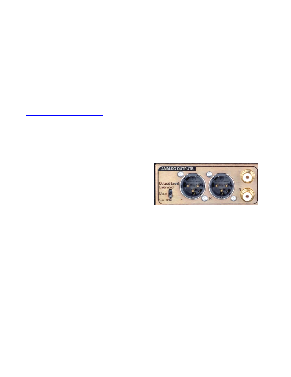
Output Level Switch
The Output Level Switch is a
three-position toggle switch
located on the rear panel. The
DAC1 PRE ships with this
switch set in the Variable
position.
CAUTION: Do not set the ‘Output Level
Switch’to ‘Calibrated’ if you are directly
driving a power amplifier or powered
speakers. The ‘Calibrated’ setting
disables the front panel volume control
and will produce an output that may be
too loud for your speakers.
Calibrated (UP) –Analog output levels are
controlled by 10-turn internal trim controls
(see page 14 for information on calibration
trimming).
Off (CENTER) –Analog XLR and RCA outputs
are muted; headphone outputs remain active.
Variable (DOWN) –Analog output levels are
controlled by the Volume Control.
The Output Level Switch does not affect the
operation of the headphone jacks (the
headphone outputs are never disabled and
the headphone level is always controlled from
the Volume Control).
TIP: If the DAC1 PRE is being used in a
critical signal chain (such as a broadcast
facility or theater) the headphone mute
switch should be defeated using the
internal jumpers. See ‘Internal Settings’
section for instructions.
Balanced XLR Analog Line Outputs
The Left and Right balanced outputs use
Neutrik™ gold-pin male XLR jacks. The XLR
shell and pin 1 (ground) are both directly
bonded to the chassis to prevent currents in
the internal ground systems. This direct
bonding also maximizes RF shielding.
The XLR output levels may be controlled from
the front panel, or may be set to fixed levels
using the internal Calibration Trimmers.
The XLR outputs have passive attenuators
that allow direct connections to a wide variety
of audio devices without a loss of dynamic
range. The 20 dB pad is usually required for
direct interfacing to power amplifiers and
powered speakers. The DAC1 PRE ships with
the 20 dB pad enabled.
Industry-standard XLR wiring:
XLR pin 2 = + Audio Out
XLR pin 3 = - Audio Out
XLR pin 1 = Cable Shield
CAUTION: If the balanced XLR outputs
are wired to an unbalanced input (using
a special adapter cable), pin 3 must be
left floating. Shorting pin 3 to ground
will increase the temperature of the
output drivers, will increase power
consumption, and may cause distortion.

DAC1 PRE Instruction Manual Rev J Page 13
Unbalanced RCA Analog Outputs
The Left and Right unbalanced
outputs use standard RCA style
jacks. The ground connections
are bonded to chassis ground
at the location where analog
ground is bonded to the
chassis. This minimizes the
effects of ground loops caused
by AC currents in the cable
shield.
The RCA output levels may be controlled from
the front panel, or may be set to fixed levels
using the internal Calibration Trimmers. In
Calibrated mode the RCA outputs are factory
preset to –10 dBV at -20 dBFS. This is typical
for most consumer-grade equipment.
TIP: Mono summing with an RCA ‘Y’
cable is not recommended as this will
cause high amounts of distortion. Mono
summing with a ‘Y’cable can be
accomplished with the use of a modified
cable by implementing a 1k Ohm series
resistor in each leg of the ‘Y’.
Note: The XLR pads do not have any effect
on the level of the RCA outputs.
The RCA output impedance is very low (30
Ohms). This makes these outputs well suited
for driving high-capacitance loads and/or
high-capacitance cables.
TIP: The RCA outputs are capable of
driving cables as long as 1360 feet (see
Table 1). But, long un-balanced cables
will generally suffer from hum problems
due to ground loops. We highly
recommend using balanced
interconnects for long runs.
Low-Impedance Passive Pads
The XLR outputs are equipped with low-
impedance passive pads that may be used to
reduce the output levels while preserving the
full dynamic range of the DAC1 PRE. The
DAC1 PRE ships with the 20 dB pads
enabled.
TIP: When directly driving power
amplifiers and powered speakers, use
‘Variable’mode and start with the
factory default 20 dB pad setting. If
necessary, change the pads to achieve a
normal listening level when the ‘Volume
Control’ is near the 12 o’clock position.
When the output pads are enabled, the
output impedance changes slightly, and the
maximum allowable cable length should be
reduced as shown in Table 1 (assuming 32
pF/foot and a maximum allowable loss of 0.1
dB at 20 kHz).
Table 1 - Cable Drive Capability
Balanced Output Drive Capability:
Attenuator Output Maximum Loss in dB
Setting (dB) Impedance Cable (ft) at 20 kHz
060 680 0.1
10 425 96 0.1
20 135 302 0.1
30 43 949 0.1
Unbalanced Output Drive Capability:
Output Maximum Loss in dB
Impedance Cable (ft) at 20 kHz
30 1360 0.1
TIP: To set the XLR outputs to typical
professional studio levels, set the pads
to 0 dB, and set the ‘Output Level Switch’
to ‘Calibrated’. If the factory settings of
the ‘Calibration Trimmers’ have not been
changed, the XLR outputs will be
calibrated to +4 dBu at -20 dBFS, and the
RCA outputs will be calibrated to -10 dBV
at -16 dBFS.
DAC1 PRE Instruction Manual Rev J Page 14
Calibration Trimmers
The Calibration
Trimmers are
located internally on
the circuit board
behind the Output
Level Switch. They
are 10-turn trimmers
and are adjustable
using a small
screwdriver.
These trimmers
provide a 2 dB per rotation adjustment with a
total control range of + 9 to +29 dBu at 0
dBFS (full-scale digital input). There are no
stops at either end of the 10-turn rotation.
CAUTION: Do not change the calibration
trimmers unless you have the ability to
accurately measure audio levels.
Factory calibration has been set so that the
output level at the balanced XLR connectors is
+4 dBu at -0 dBFS. This is exactly 20 dB
lower than a typical alignment of +4 dBu at
-20 dBFS. The lower level is appropriate for
most powered monitors.
TIP: To set the XLR outputs to typical
professional studio levels, set the pads
to 0 dB, and set the ‘Output Level Switch’
to ‘Calibrated’. If the factory settings of
the ‘Calibration Trimmers’ have not been
changed, the XLR outputs will be
calibrated to +4 dBu at -20 dBFS, and the
RCA outputs will be calibrated to -10 dBV
at -16 dBFS.
The factory-preset levels may be increased by
5 dB or decreased by 15 dB in order to
conform to other studio reference levels. This
range of levels is also well suited for direct
connection to the balanced line-level inputs
on most power amplifiers. Most professional
equipment will work well at these levels.
Note: The Calibration Trimmers have no
effect on the output levels when the Output
Level Switch is set to Variable.
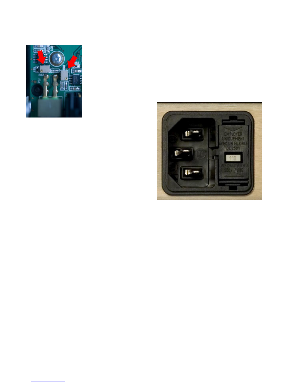
AC Power-Entry and Fuse Module
The AC power input uses a standard IEC type
connector. One USA-compatible power cord
is included with DAC1 PRE converters
shipped to North America. IEC style power
cords in country-specific configurations are
available in your locality.
Fuse Holder
The fuse holder is built into a drawer next to
the IEC power connector. The drawer
requires two 5 x 20 mm 250 V Slo-Blo®Type
fuses. The drawer includes a voltage
selection switch with two settings: 110 and
220. The fuse rating for all voltage settings
is 0.50 Amps.
The AC input has a very wide input voltage
range and can operate over a frequency
range of 50 to 60 Hz. At 110, the DAC1 PRE
will operate normally over a range of 90 to
140 VAC. At 220, the DAC1 PRE will
operate normally over a range of 175 to 285
VAC.
Caution: Always install the correct fuses.
Always insure that the voltage setting is
correct for your locality.

DAC1 PRE Instruction Manual Rev J Page 15
Internal Settings
Removing Top Cover
The DAC1 PRE cover must be removed to
gain access to the jumpers. Do not attempt
to remove the faceplate or rear panel.
CAUTION: The DAC1 PRE contains static
sensitive components and should only be
opened by qualified technicians. Static
discharge may cause component failures,
may affect the long-term reliability, or
may degrade the audio performance. Use
a static control wrist strap when
changing jumper settings.
CAUTION:
Disconnect AC power by unplugging
the power cord at the back of the
DAC1 PRE.
Remove only the 8 screws holding the
cover (4 on each side).
Do not remove any screws on front or
rear panels.
Never remove the power entry safety
cover in the rear corner of the DAC1
PRE.
Always connect a static-control wrist
strap to the chassis before touching
any internal component.
Jumpers
The following functions are jumper
configured:
Headphone Gain Range Adjustment
Headphone Switch Disable
XLR Output Pads
XLR Output Pad Selection (P5, P6,
P7, and P8):
Four 8-pin headers (P5, P6, P7, and P8) allow
selection of the output level at the XLR jacks.
One pair of 8-pin headers controls the output
level at each XLR jack as follows:
0 dB - (Attenuator disabled) –(Jumper
plug between pins 1 and 2 of each
header)
-10 dB –(Jumper plug between pins 3 and
4 of each header)
-20 dB –***(Jumper plug between pins 5
and 6 of each header)
-30 dB –(Jumper plug between pins 7 and
8 of each header)
*** = Factory Default
Photo 1 - XLR Output Pad Selection (P5,
P6, P7, and P8 )

DAC1 PRE Instruction Manual Rev J Page 16
Headphone Switch Disable (JP2
and JP4):
The DAC1 PRE is configured so that the
analog outputs will mute when a headphone
plug is inserted into the left-hand jack. This
is convenient when the user wishes to switch
between headphones and speakers. This
feature can be defeated by adding jumpers at
JP1 and JP2.
JP1 and JP2 should be configured as follows:
Headphone Switch enabled*** (Jumpers
Removed)
Headphone Switch disabled (Jumpers
Inserted)
Photo 2 - Headphone Switch Disable (JP1
and JP2)
Headphone Gain Reduction (JP3
and JP4):
The gain range of the HPA2™ can be set
using jumpers JP3 and JP4. When jumpers
are installed at position “A” the headphone
amplifier gain is decreased by 20 dB. When
jumpers are installed at position “B” the
headphone amplifier gain is decreased by 10
dB.
The ideal gain setting permits the user to set
the front-panel Volume Control above 40%
(10 o’clock) without the headphone volume
being too loud.
JP3 and JP4 are factory installed at position
“B” to reduce the headphone output by 10
dB. This setting is best for most applications.
Remove the jumpers if you need more gain,
or move them to position “A” if you need less
gain.
Photo 3 –Headphone Gain Reduction
(JP3 and JP4)
DAC1 PRE Instruction Manual Rev J Page 17
Rack Mounting
An optional rack mount adapter allows the
mounting of any two Benchmark System1™
products in a single rack space. A Blank
Rack Panel can be added when only one unit
is installed in the rack mount adapter.
The System1™ Universal Rack Adapter
and Blank Rack Panel are available from
Benchmark.
Call us, visit our website
(http://www.BenchmarkMedia.com), or
contact your dealer to purchase these
accessories.
System1™ Universal Rack Adapter
The Universal Rack Mount Adapter is a
tray that mounts up to two System1™
products in a single race space. The tray
accepts any combination of System1™
products (with or without rack-mount type
faceplates).
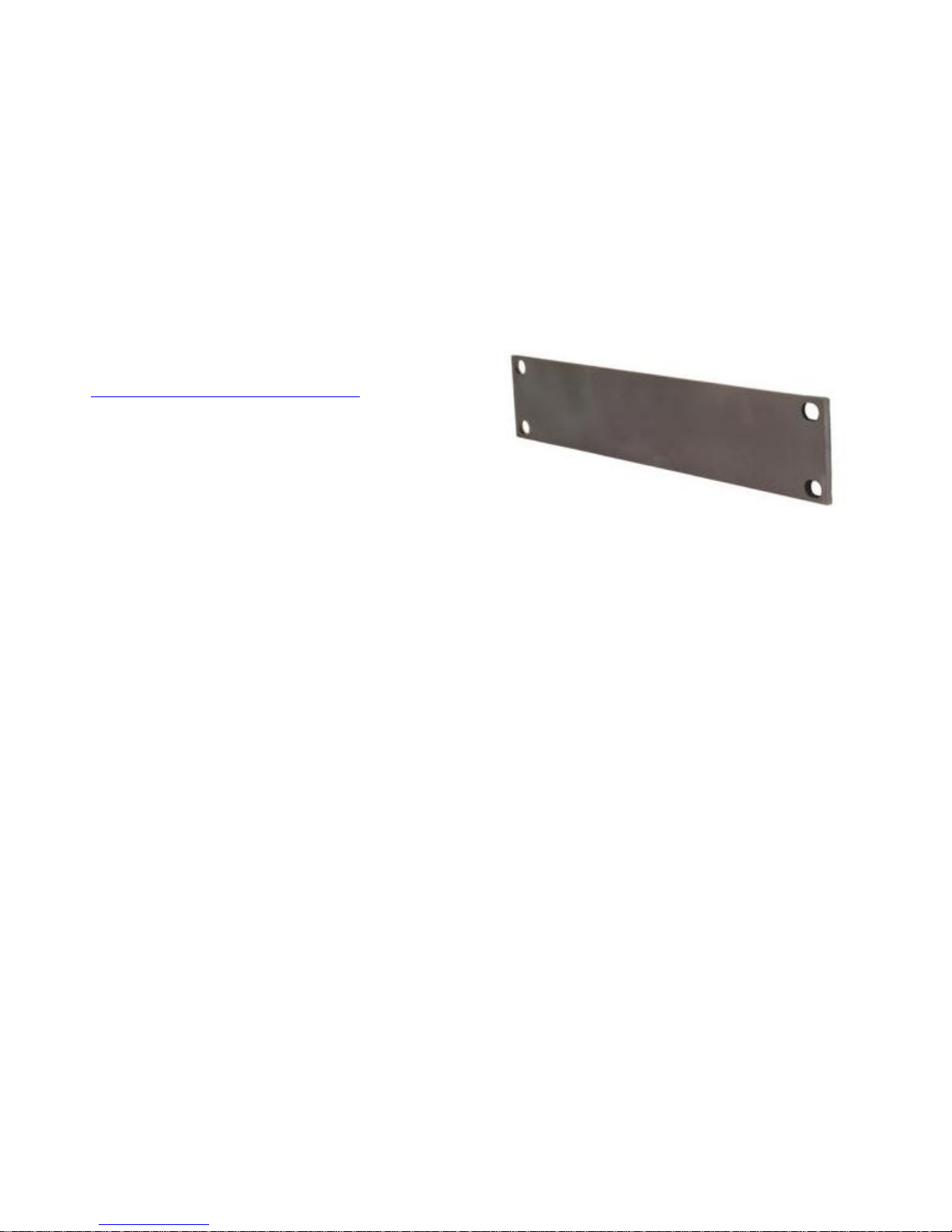
Blank Rack Panel
The Blank Rack Panel is a ½-wide 1-RU
black-anodized aluminum panel for covering
an unused slot in a System1™ Universal
Rack Adapter.

DAC1 PRE Instruction Manual Rev J Page 18
Benchmark Technologies
HPA2™ Headphone Amplifier
The DAC1 PRE headphone output is driven
by Benchmark’s signature HPA2™ headphone
amplifier. This high-current, high-output
amplifier has an output impedance of near 0-
Ohms. It is designed to drive loads as low as
30 Ohms without any increase in distortion.
It also has sufficient amplitude to drive low-
sensitivity 600-Ohm headphones.
The HPA2™ includes current-limiting circuits
that fully protect against damage from short
circuits. This is important because the right
channel of a headphone amplifier will
experience a short whenever a mono phone
plug is inserted into the stereo headphone
jack. Shorts may also occur when a plug is
partially inserted.
0-Ohm Output Impedance
Most headphone amplifiers use series
resistors to maintain stability and protect
against short-circuit conditions. These
resistors are usually at least 30 Ohms, and
have a negative impact on performance. A
headphone amplifier with series resistors may
measure very well when driving resistive
loads. However, the same amplifier will
measure very poorly when driving a
headphone load. Unfortunately, most
manufacturers do not specify headphone
amplifier performance with anything other
than ideal resistive loads. Our measurements
show that headphones do not behave like
resistive loads.
Headphone Performance
In our tests we have measured substantial
distortion across resistors that are wired in
series with headphones. We conducted
measurements with a variety of headphones.
In general, distortion increases as headphone
impedance decreases. This distortion can be
eliminated with a properly designed 0-Ohm
headphone amplifier.
The performance of the HPA2™ does not
change when headphones are driven. THD+N
measurements for no-load, 30-Ohm resistive
loads, 30-Ohm headphone loads, and 600-
Ohm headphone loads are virtually identical.
The HPA2™ will substantially improve the
sound of 30 and 60-Ohm headphones. It will
make very noticeable improvements with
600-Ohm headphones.
UltraLock™ Clock System
Accurate 24-bit audio conversion requires a
very low-jitter conversion clock. Jitter can
very easily turn a 24-bit converter into a 16-
bit converter (or worse). There is no point in
buying a 24-bit converter if clock jitter has
not been adequately addressed.
Jitter is present on every digital audio
interface. This type of jitter is known as
‘interface jitter’ and it is present even in the
most carefully designed audio systems.
Interface jitter accumulates as digital signals
travel down a cable and from one digital
device to the next. If we measure interface
jitter in a typical system we will find that it is
10 to 10,000 times higher than the maximum
allowable level for accurate 24-bit conversion.
Fortunately, interface jitter has absolutely no
effect on the audio unless it influences the
conversion clock in an analog-to-digital
converter (A/D) or in a digital-to-analog
converter (D/A).
Many converters use a single-stage Phase
Lock Loop (PLL) circuit to derive their
conversion clocks from AES/EBU, Wordclock,
or Superclock reference signals. Single-stage
PLL circuits provide some jitter attenuation
above 5 kHz but none below 5 kHz.
Unfortunately, digital audio signals often have
their strongest jitter components at 2 kHz.
Consequently, these converters can achieve
their rated performance only when driven
from very low jitter sources and through very
short cables. It is highly unlikely that any
converter with a single-stage PLL can achieve
better than 16 bits of performance in a typical
installation. Specified performance may be
severely degraded in most installations.

DAC1 PRE Instruction Manual Rev J Page 19
Better converters usually use a two-stage PLL
circuit to filter out more of the interface jitter.
In theory, a two-stage PLL can remove
enough of the jitter to achieve accurate 24-bit
conversion (and some do). However, not all
two-stage PLL circuits are created equal.
Many two-stage PLL’s do not remove enough
of the low-frequency jitter. In addition, two-
stage PLL circuits often require several
seconds to lock to an incoming signal.
Finally, a two-stage PLL may fail to lock when
jitter is too high, or when the reference
sample frequency has drifted.
UltraLock™ converters exceed the jitter
performance of two-stage PLL converters, and
are free from the slow-lock and no-lock
problems that can plague two-stage PLL
designs. UltraLock™ converters have
extremely high immunity to interface jitter
under all operating conditions. No jitter-
induced artifacts can be detected using an
Audio Precision System 2 Cascade test set.
Measurement limits include detection of
artifacts as low as –140 dBFS, application of
jitter amplitudes as high as 12.75 UI, and
application of jitter over a frequency range of
2 Hz to 200 kHz. Any AES/EBU signal that
can be decoded by the AES/EBU receiver will
be reproduced without the addition of any
measurable jitter artifacts.
The DAC1 PRE, DAC1, DAC-104, ADC1 and
the ADC-104 employ Benchmark’s
UltraLock™ technology to eliminate jitter-
induced performance problems. UltraLock™
technology isolates the conversion clock from
the digital audio interface clock. Jitter on a
D/A digital audio input, or an A/D reference
input can never have any measurable effect
on the conversion clock of an UltraLock™
converter. In an UltraLock™ converter, the
conversion clock is never phase-locked to a
reference clock. Instead the converter
oversampling-ratio is varied with extremely
high precision to achieve the proper phase
relationship to the reference clock. The clock
isolation of the UltraLock™ system insures
that interface jitter can never degrade the
quality of the audio conversion. Specified
performance is consistent and repeatable in
any installation with cables of any quality
level!
How does conversion clock jitter
degrade converter performance?
Problem #1: Jitter phase modulates the
audio signal. This modulation creates
sidebands (unwanted tones) above and below
every tone in the audio signal. Worse yet,
these sidebands are often widely separated
from the tones in the original signal.
Jitter-induced sidebands are not musical in
nature because they are not harmonically
related to the original audio. Furthermore,
these sidebands are poorly masked (easy to
hear) because they can be widely separated
above and below the frequencies of the
original audio tones. In many ways, jitter
induced distortion resembles intermodulation
distortion (IMD). Like IMD, jitter induced
distortion is much more audible than
harmonic distortion, and more audible than
THD measurements would suggest.
Jitter creates ‘new audio’ that is not
harmonically related to the original audio
signal. This ‘new audio’ is unexpected and
unwanted. It can cause a loss of imaging, and
can add a low and mid frequency ‘muddiness’
that was not in the original audio.
Jitter induced sidebands can be measured
using an FFT analyzer.
Problem #2: Jitter can severely degrade the
anti-alias filters in an oversampling converter.
This is a little known but easily measurable
effect. Most audio converters operate at high
oversampling ratios. This allows the use of
high-performance digital anti-alias filters in
place of the relatively poor performing analog
anti-alias filters. In theory, digital anti-alias
filters can have extremely sharp cutoff
characteristics, and very few negative effects
on the in-band audio signal. Digital anti-alias
filters are usually designed to achieve at least
100 dB of stop-band attenuation. But, digital
filters are designed using the mathematical
assumption that the time interval between
samples is a constant. Unfortunately, sample
clock jitter in an A/D or D/A varies the
effective time interval between samples. This
variation alters the performance of these

DAC1 PRE Instruction Manual Rev J Page 20
carefully designed filters. Small amounts of
jitter can severely degrade stop-band
performance, and can render these filters
useless for preventing aliasing.
The obvious function of a digital anti-alias
filter is the removal of audio tones that are
too high in frequency to be represented at the
selected sample rate. The not-so-obvious
function is the removal of high-frequency
signals that originate inside the converter
box, or even originate inside the converter IC.
These high-frequency signals are a result of
crosstalk between digital and analog signals,
and may have high amplitudes in a poorly
designed system. Under ideal (low jitter)
conditions, a digital anti-alias filter may
remove most of this unwanted noise before it
can alias down into lower (audio) frequencies.
These crosstalk problems may not become
obvious until jitter is present.
Stop-band attenuation can be measured very
easily by sweeping a test tone between 24
kHz and at least 200 kHz while monitoring the
output of the converter.
Put UltraLock™ converters to the
test:
We encourage our customers to perform the
above tests on UltraLock™ converters (or let
your ears be the judge). There will be
absolutely no change in performance as jitter
is added to any digital input on an
UltraLock™ converter. Try the same tests
on any converter using conventional single or
two-stage PLL circuits. Tests should be
performed with varying levels of jitter and
with varying jitter frequencies. The results will
be very enlightening. Jitter related problems
have audible (and measurable) effects on A/D
and D/A devices. Practitioners of Digital Audio
need to understand these effects.
Is it possible to eliminate all of
the effects of jitter in an entire
digital audio system?
Interface jitter will accumulate throughout
even the most carefully designed digital audio
system. Fortunately, interface jitter can
only degrade digital audio if it affects the
sampling circuit in an analog-to-digital or
digital-to-analog converter. Any attempt to
cure jitter outside of an A/D or D/A will prove
expensive and, at best, will only partially
reduce jitter-induced artifacts. Dedicated
clock signals (word clock, and super clock,
etc.) are often distributed to A/D converters
and D/A converters in an attempt to reduce
jitter. Again, these are only partial solutions
because jitter even accumulates in these
clock distribution systems. Furthermore, a
poor quality master clock generator can
degrade the performance of the entire system
(if converter performance is dependent upon
reference clock quality). Jitter free A/D and
D/A converters are the only true insurance
against the ill effects of jitter. UltraLock™
converters are jitter-immune under all
operating conditions (they will never add
audible jitter induced artifacts to an audio
signal).
What UltraLock™ converters
cannot do:
UltraLock™ converters cannot undo damage
that has already been done. If an A/D with a
jitter problem was used to create a digital
audio signal, then there is nothing that can be
done to remove the damage. Jitter-induced
sidebands are extremely complex and cannot
be removed with any existing audio device.
Therefore, it is very important to attack jitter
at both ends of the audio chain. The DAC1
PRE is a great start, as it will allow accurate
assessment of various A/D converters. It is
impossible to audibly evaluate A/D
performance without a good D/A. The
consistent performance delivered by the
DAC1 PRE eliminates one major variable:
jitter.
Table of contents
Other Benchmark Media Converter manuals

Benchmark
Benchmark DAC1 USB User manual

Benchmark
Benchmark ADC16 User manual

Benchmark
Benchmark DAC2 DX User manual

Benchmark
Benchmark ADC1 USB User manual

Benchmark
Benchmark DAC1 HDR User manual

Benchmark
Benchmark ADC1 USB User manual

Benchmark
Benchmark AD2402-96 User manual

Benchmark
Benchmark DAC3 B User manual

Benchmark
Benchmark DAC3 HGC Quick start guide

Benchmark
Benchmark DAC2 DX User manual


