Benchmark AD2402-96 User manual

BENCHMARK MEDIA SYSTEMS, INC.
AD2402-96 / AD2K+ TWO CHANNEL, 96-kHz
ANALOG TO DIGITAL CONVERTER
11/09/04 Revision - Absolute Input Polarity Correction pg. 17
Operating Manual
Revision
1

AD2402-96 - ANALOG TO DIGITAL CONVERTER
Operating Manual
©BENCHMARK MEDIA SYSTEMS, INC.
5925 Court Street Road
Syracuse, NY 13206-1707
Phone (315) 437-6300• Fax (315) 437-8119
www.benchmarkmedia.com

Table of Contents
Digital Input Connectors 19
System Overview 5 “In” Connector 19
Sample Rate 5 “Loop” Connector 21
Word Length 5 Digital Outputs 21
Digital Audio Reference 5 Using the Meters 22
Digital to Digital Processing 6
Using the Peak Hold Function 22Digital Outputs 6
Selecting Meter Range 22
88.2 and 96 kHz Operation 6
Meter Time-Constants 22
“Dual Cable” 88.2 and 96 kHz Modes 7
Fast Decay Time-Constant 23
“Single Cable” 88.2 and 96 kHz Modes 8
Slow Decay Time-Constant 23
Analog Inputs 8
Meters 8
“FSD” Meters 24
Power Supply Connection 9 What is “FSD”? 24
Front Panel 10 How is “FSD” Different from “0 dBFS”? 24
“Power” Switch 10 How is “FSD” Different from “Over”? 24
“On” LED 10 The Fallacy of “Over” Indicators 25
“Low Battery” LED 10 Do “Over” Indicators Have a Place? 25
“Input Level” Switch 11 Design Philosophy 27
“Lock” LED 12 Specifications 28
“Word Length Mode” Switch 13
“Sample Rate” Switch 13 Jitter and it’s Effects 31
“Meter Scale” Switch 15 Confusion over Jitter 31
Digital LED Meters 16 How Does Relate? 31
“Aux Output Word Length” Switch 16 How Can We Measure Jitter? 31
“Format” Switch 17 Why so Low? 32
Rear Panel 18 Jitter Degrades Digital Filters 32
Additional Information 34
Analog Inputs 18
DC Power Input 19
Fuse 19
Word Length Reduction 35
What is the Appropriate Setting? 35

NN™ or NS™ Processes in Cascade 36
Why NN3™ for Cascaded 16-bit? 37
Dither 37
Will Dither Damage My Speakers? 40
How is the Performance Measured? 40
Avoid Truncation without Dither 40
Digital Word Length Increases… 41
Additional Information 41
Word Length Reduction Curves 43

Chapter
1
AD2402-96 - OPERATING MANUAL
System Overview
A brief overview of the AD2402-96
The AD2402-96 is a 2-channel, portable version of the Benchmark 4-channel AD2404-96 and 8-
channel AD2408-96 24-bit 96-kHz converters. The Benchmark AD2404 was designed to
provide the best possible sonic performance. The AD2402-96 faithfully replicates this
performance in a portable package. The circuit design, components, construction
techniques, and sonic performance of the AD2402-96 are identical to those of the AD2404.
Sample Rate
The AD2402-96 operates at fixed sample rates of 44.1 48, 88.2 and 96-kHz. In addition, a
“Variable” or “Varispeed” mode allows the converter to operate at any sample rate between 24-
kHz and 100-kHz.
Word Length
Output word lengths can be set at 24, 20, or 16-bits. The 20 and 16-bit word lengths are re-
dithered from 24-bits using either the Benchmark NN™ or NS™ word length reduction
systems. The NN™ and NS™ systems are optimized for the selected sample rate, and for the
number of bits being removed. NN3 and NS3 can achieve near 20-bit performance on a 16-bit
recorder. The NN1, NN2, NS1, NS2, settings are optimized for noisier recording environments.
TPDF (white noise) dither is also a selectable output choice. A unique feature of the AD2402-
96 allows simultaneous 24 and 16-bit outputs.
Digital Audio Reference
A digital audio input jack allows the AD2402-96 to phase-lock to an external AES or SPDIF
digital audio reference. Most 2-channel applications will not require an external reference
and many users will never need to use the external reference input. However, the external
reference is provided to allow phase-accurate multi-track recording with two or more AD2402-96
5

AD2402-96 - OPERATING MANUAL
converters. An external reference is also required whenever the converter is operated in the
“Varispeed” mode.
Digital to Digital Processing
The digital audio input jack also serves as the input for all Digital-to-Digital processing
functions. These functions include; Word Length Reduction, Pro to Consumer and Consumer
to Pro channel-status conversion, SPDIF to AES/EBU and AES/EBU to SPDIF conversion,
SCMS override, and 75 ohm unbalanced to 110 ohm balanced conversion. The D-to-D feature
also allows the AD2402-96 to act as a 1 in 4 out digital distribution amplifier! For processing a
24-bit signal down to 16-bit, as would be the case in mastering a CD or producing a DAT tape,
the user can take the 24-bit signal into the AD2402-96 digital input. Then the user should select
the D-to-D function, and monitor each word length reduction setting to determine which best
complements the recording.
Digital Outputs
Four digital output jacks provide a unique set of features. Two outputs are 75-Ohm
unbalanced, and two outputs are 110-Ohm balanced. All outputs can operate in either
professional or consumer status formats. All outputs support 16, 20, or 24-bits, but the two
“Aux.” outputs can be set to operate at 24-bits while the “Main” outputs operate at either 16, 20,
or 24-bits. All outputs support stereo operation at sample rates up to 100 kHz on a single digital
cable. In addition, a “Main” and “Aux.” output pair can be used to record “dual-cable” 88.2 or
96 kHz.
88.2 and 96 kHz Operation
88.2 and 96 kHz sample rates are supported using either a “Single Cable” interface mode
(also know as “AES3 Multichannel Mode”) or a “Dual Cable” interface mode (also known as
“AES3 Single Channel Double Sampling Frequency Mode”).
6

AD2402-96 - OPERATING MANUAL
“Dual Cable” 88.2 and 96 kHz Modes
The “Dual Cable” 88.2 and 96 kHz modes provide a means for recording at sample rates up to
96 kHz on equipment that was originally designed for 48 kHz. When using the “Dual Cable”
mode at 96 kHz, a single audio channel will occupy two tracks on the digital recorder. In this
mode, two successive samples of a single high sample-rate channel are transmitted in place of a
pair of low sample-rate channels. Two digital cables are required for two channels. Using the
“Dual Cable” mode, a standard DAT machine can record one channel at 96 kHz, and an ADAT,
DA88, or other digital multi track devices can record up to 4-channels at 96 kHz.
Caution: Tapes produced in “Dual Cable” mode will appear to be compatible with
standard playback and editing equipment, but actually are not compatible. Do not
use this mode unless you have all of the equipment necessary to edit and play
“Dual Cable” 96 kHz recordings. Any tapes recorded in this mode should be
carefully labeled to avoid confusion. Playback on incompatible systems will
introduce unwanted artifacts that may not be immediately noticeable.
7

AD2402-96 - OPERATING MANUAL
“Single Cable” 88.2 and 96 kHz Modes
The “Single Cable” 88.2 and 96 kHz modes are only compatible with digital recorders that are
specifically designed for 88.2 and 96 kHz. In this mode, a channel pair is transmitted on a single
digital cable, at a frame rate equal to the sampling rate.
Analog Inputs
The analog inputs support balanced or unbalanced inputs. Input sensitivity is adjustable in
2 dB steps. Maximum sensitivity is +14 dBu at full scale (0 dBFS). Minimum sensitivity is +24
dBu at full scale (0 dBFS).
Sensitivities greater than +14 dBu have not been included since they would compromise the
dynamic range of the AD2402-96.
Balanced inputs are included since they are the best method of signal interconnection to a
microphone preamplifier, whether the preamplifier has balanced or unbalanced outputs. For
more information on proper cable wiring to receive a signal from an unbalanced source, known
as forward referencing, see page 15 of the Benchmark Media Systems, Inc. application note: “A
Clean Audio Installation Guide”.
The Clean Audio Installation Guide PDF file is available for download from our web site. The
URL is http://www.benchmarkmedia.com/pdf/caig.pdf.
Balanced Inputs: Pin 1 = Shield, Pin 2 = -Signal, and Pin 3 = +Signal (revised).
Unbalanced Inputs: Pin 1 = Shield, Pin 2 = Signal Ground, Pin 3 = Signal (revised).
Caution: Connections from unbalanced outputs will not function properly if
pin 2on the input to the AD2402-96 is left floating (revised).
Meters
Each conversion channel is equipped with a multi-function 9-segment LED meter. A “Meter
Scale” switch selects either a 6-dB/step scale or a 1-dB/step scale, and controls the peak hold
8

AD2402-96 - OPERATING MANUAL
function, which is referenced to the 1-dB/step scale. Metering is fully digital and post conversion
for absolute accuracy.
Power Supply Connection
The AD2402-96 is equipped with an industry standard 4-pin XLR power connector, and may be
powered from a 12 V battery, or from an external DC power supply.
The input voltage should be between 11 and 18 VDC.
Pin 1 = Ground,
Pin 4 = +11 to +18 VDC at 0.8 A.
Pins 2 and 3 are not connected internally.
9

Chapter
2
AD2402-96 - OPERATING MANUAL
Front Panel
Detailed Information on the AD2402-96 front panel.
Figure 1. AD2402-96 Front Panel
“Power” Switch
The power switch is equipped with a short handle to prevent accidental shut off. If you are
monitoring the output of the AD2402-96 with headphones or speakers, mute them before turning
this switch on or off. Also, it is a good idea to turn this switch off before connecting or
disconnecting the DC power.
“On” LED
The green “On” LED will light whenever the power switch is on and the input voltage is high
enough for normal operation. The “On” LED will not light if the input voltage is less than 10.5
V. An illuminated “On” LED is your assurance that the input voltage is high enough for normal
operation.
“Low Battery” LED
The AD2402-96 is equipped with a red “Low Batt” LED. The low-battery light is calibrated for
use with 12-volt lead-acid “gel-cell” batteries but may be adjusted for use with other types of
batteries. Lead-acid batteries should be charged shortly after the “Low Batt.” LED turns on. Note
that the AD2402-96 will continue to operate normally as long as the green “On” LED is
10

AD2402-96 - OPERATING MANUAL
illuminated. Typically, the AD2402-96 can operate for 1-hr with the red LED illuminated before
the green LED will turn off. However, prolonged and/or frequent deep discharge cycles
(operation with the red LED on) will shorten the lifetime of a lead-acid battery. Lead-acid
batteries should be recharged after every use, and should be stored in a cool location, fully
charged.
“Input Level” Switch
This rotary switch adjusts the sensitivity of the analog inputs. The numbers (from +24, down to
+14) indicate the level (in dBu) at which a full-scale digital code will be reached. At “+24” the
converter will clip when the analog input reaches or exceeds +24 dBu. At “+14”, the converter
will clip when the analog input reaches or exceeds +14 dBu.
The “Input Level” switch should be set so that the AD2402-96 will clip 3 to 6 dB before the
microphone preamplifier. For example, if your microphone preamp has a maximum output level
of +24 dBu, then set the switch to “+20”. This will reserve 4 dB of headroom in the preamplifier.
If too much headroom is allowed in the microphone preamplifier, noise from the preamp may
reduce the dynamic range of your recording. If no headroom is provided, the microphone
preamp may add distortion to your recording.
Set the “Input Level” switch to match the performance of your preamp. Do not use this switch to
adjust levels during a recording. Instead, use the gain control on your microphone preamp. This
switch is used specifically to calibrate the AD2402-96 to a line level source, mixing console or
microphone pre-amp. It is NOT intended as a gain control for adjustment during a recording
session. Set the switch in accordance with your pre-amp or mixer before beginning the recording
session.
+24 dBu is a very hot level and is often only available at the output of high quality microphone
preamplifiers. Some battery operated microphone preamps cannot achieve +24 dBu without
clipping, and will require setting the AD2402-96 to a lower clip point (typically “+20” or “+18”).
Use the “+14” setting for unbalanced inputs. Some consumer grade devices are not capable of
achieving even +14 dBu levels without clipping. These low-level unbalanced outputs are not a
good match for the performance of the AD2402-96 but can be connected through an external
balancing interface amplifier if necessary.
All preamplifiers have an intrinsic noise floor that is set by basic physics. The contributing
elements are the source impedance of the microphone, usually between 50 and 200 ohms, the
noise of the first stage of the preamplifier, the noise of second fixed gain stage, and the noise of
the output stage.
A preamplifiers dynamic range is defined by the difference between this intrinsic internal noise
level and the peak output clip point of the preamp. If the clip point is reduced to say + 12 dBu,
and nothing short of miraculous is done to reduce the second and third stage noise of the
preamplifier, the dynamic range of the pre-amp will be limited to much less than the AD2402-96.
11

AD2402-96 - OPERATING MANUAL
The only way to achieve a low noise level with the preamplifier is to use extremely low internal
impedances and ultra low-noise operational amplifiers. Both of these required techniques are
power hungry and incompatible with portable pre-amps where long battery life is an objective.
Therefore, avoid microphone preamps that cannot achieve at least +16 dBu out, without clipping.
Even then the dynamic range of the preamp and not the AD2402-96 will, in all probability, be
limiting the dynamic range of your high-quality 24-bit recordings.
“Lock” LED
The “LOCK” LED will turn on whenever the AD2402-96 is locked to a reliable digital audio
reference of the correct frequency. The digital input/reference signal must be AES/EBU or
SPDIF.
The AD2402-96 will lock at 1:1 or 2:1 ratios. For example, if the AD2402-96 is operating at 96
kHz, the converter will lock to either a 48 kHz or 96 kHz digital audio signal.
If the lock light is off, the AD2402-96 is operating as clock master (using the internal crystal
reference).
Important Note:
An external reference is normally not required for 2-channel recording. The lock
LED will not be on when the AD2402-96 is operating as a stand-alone (clock
master) device. This is not an indicator of an error.
A digital audio input is required in the “Var” (variable sample rate) and “D-to-D” (digital to
digital) modes. It is optional in all other modes.
When locking to an external reference, the “Lock” LED will flash for several seconds while
the PLL is acquiring lock and will be lit once internal lock is achieved.
A continuously flashing “Lock” light indicates a lock error.
Possible causes of a lock error include:
• Reference sample frequency is incorrect or out of range.
• Reference signal is neither AES/EBU nor SPDIF.
• Reference signal is being received with errors.
• Reference is required (“Var” and “D-to-D” modes) but is not present.
12

AD2402-96 - OPERATING MANUAL
Note: The AD2402-96 automatically mutes for the first 10 seconds after applying
power. While muted, the “Lock” LED will flash nine times indicating that
automatic calibration is in progress. This is not an indication of a lock error.
“Word Length Mode” Switch
The “Word Length Mode” switch is a twelve-position rotary switch. It selects 24, 20, or 16-bit
word lengths at the main outputs. All 16 and 20-bit Word Length Reduction (WLR) modes are
TPDF dithered prior to word length reduction.
There are seven word length reduction modes (“TPDF”, “NN1”, “NN2”, and “NN3”, “NS1”,
“NS2”, and “NS3”). All forms of word length reduction raise the noise floor of a digital
transmission system. TPDF dither is spectrally flat, it is not shaped, and will sound noisier than
any of the “NN” or “NS” modes. “NS1”, “NS2”, and “NS3” are noise-shaping modes which are
psycho-acoustically optimized to take advantage of the ear’s low-level sensitivity curve. “NS1”,
“NS2”, and “NS3” will sound 6, 12, and 18 dB quieter than “TPDF” respectively. “NS1”,
“NS2”, and “NS3” can provide 17-bit, 18-bit, and 19-bit performance respectively at a 16-bit
word length. At 20-bits, “NS1” and “NS2” provide 21-bit and 22-bit performance respectively.
For the best performance, use the maximum word length that is compatible with your digital
audio equipment. Maintain 24 or 20-bit word lengths as long as possible. If WLR to 16-bits
is required, do so at the latest possible point and time. Avoid processing 16-bit signals. In
general, NS2 will produce the quietest 20-bit signal, and NS3 will produce the quietest 16-bit
signal.
Caution: Do not apply word length reduction when using the D-to-D function for
dubbing 16-bit tapes. Use the “24” setting for all D-to-D functions unless you
wish to simultaneously reduce the word length of the input digital audio signal. Use
the “24” setting for 16-bit to 16-bit dubbing, 20-bit to 20-bit dubbing, and 24-bit to
24-bit dubbing. For more information see Table 1.
“Sample Rate” Switch
The “Sample Rate” Switch is a twelve-position rotary switch. This switch selects the sample clock
frequency, the PLL (Phase Locked Loop) mode, dual or single cable interface modes, and digital-
to-digital functions.
For typical A/D conversion applications, select either “44.1” or “48”. If an external digital
audio reference is connected to the “Digital Input”, the AD2402-96 will automatically switch from
internal to external clock, and the “Lock” LED will turn on. A feature unique to Benchmark
13

AD2402-96 - OPERATING MANUAL
converters is that all automatic transitions between external and internal clock are silent and will
not interrupt the operation of the A/D converter.
For A/D conversion at non-standard frequencies, use the “Var” (varispeed) setting. In
varispeed mode, the A/D sample rate is determined by the sample rate of the digital audio input
signal. If no digital input is present, the converter will mute, and the digital outputs will default to
44.1 kHz. The “Var” mode supports any sample rate between 28 and 100 kHz but does not have
the jitter immunity provided by the fixed frequency modes. Use fixed frequency mode whenever
possible.
For A/D conversion at high sample-rates using “Single-Cable” interfaces, select either “88.2”
or “96”. These single-cable 88.2 and 96 kHz settings are labeled in white. These settings are
compatible with high sample-rate recorders that are specifically designed to support single-cable
interfaces.
For A/D conversion at high sample-rates using “Dual-Cable” interfaces, select either “88.2”
“Dual-Cable” or “96” “Dual-Cable”. These dual-cable 88.2 and 96 kHz settings are labeled in
black. These settings allow high sample-rate recording on 44.1 and 48 kHz recorders. Channel 1
will be directed to the “Main” outputs. Channel 2 will be routed to the “Aux” outputs. Two
tracks will be required for each channel.
Caution: In “Dual Cable” mode, each digital output is dedicated to a single audio
channel instead of a stereo pair. “Dual Cable” recordings require 88.2 and 96 kHz
playback and editing equipment. Furthermore, “Dual Cable” recordings must
always be dubbed and transferred from 44.1 and 48 kHz recorders in the digital
domain. The “Dual Cable” digital output from the recorder must always be mixed,
edited, processed, and converted to analog using 88.2 or 96 kHz equipment. Label
all “Dual-Cable” recordings carefully! A 96 kHz “Dual Cable” recording may
appear to play properly at the analog outputs of a 48 kHz machine, but these analog
output signals will actually contain unwanted alias tones that cannot be removed with
a filter.
For Digital to Digital processing, select “D-to-D”. The “D-to-D” mode provides high-quality
digital to digital processing functions that can be used individually or in combination.
“D-to-D” functions include; word length reduction, SPDIF to AES/EBU format conversion,
AES/EBU to SPDIF format conversion, and SCMS copyright correction. In addition, the
AD2402-96 can act as a 1-in, 4-out digital distribution amplifier.
The digital input will accept either consumer or professional format digital audio. The “Format”
switch always determines the format of all four digital outputs.
14

AD2402-96 - OPERATING MANUAL
Important Note: If the “Word Length” switch is set at “24”, the “D-to-D” mode
will alter the status bits but will not alter audio data bits. All other “Word Length”
settings will add dither noise to the audio. Use the “24” setting whenever you do
not wish to alter the word length of the audio signal. However, if you wish to
reduce the word length of the audio data, use the “Word Length” switch to select
the desired word length reduction function. See Table 1.
Table 1 - Word Length Mode Settings for D-toD Processing
Input Word Lengt
h
Output Word Lengt
h
Word Length Mode Switch Setting
s
16 16 24
18 16 16NS3, 16NS2, 16NS1, 16 NN3, 16NN2, 16NN1, or 16TPDF
18 18 24
20 16 16NS3, 16NS2, 16NS1, 16 NN3, 16NN2, 16NN1, or 16TPDF
20 20 24
24 16 16NS3, 16NS2, 16NS1, 16 NN3, 16NN2, 16NN1, or 16TPDF
24 20 20NS2, 20NS1, 20NN1, 20TPDF
24 24 24
“Meter Scale” Switch
The “Meter Scale” switch selects one of three digital meter functions. The down position sets
the meter scale to 6-dB steps. The center position sets the meter scale to 1-dB steps. The up
position sets the meter scale to 1-dB steps with peak hold. Moving the switch to the center
position will clear the peak hold. Note that the bottom of the 1-dB scale is expanded and includes
a -20 dBFS LED that can be used to set the input level relative to a 0-dB house reference. The “6
dB” setting makes it easy to verify that signals are present at the analog inputs. The “1 dB”
and “Hold” settings permit accurate monitoring near full scale.
15

AD2402-96 - OPERATING MANUAL
Digital LED Meters
Each conversion channel is equipped with a multi-function 9-segment LED meter. A “Meter
Scale” switch selects either a 6 dB/step or 1 dB/step scale and controls the peak hold function.
Metering is fully digital and post conversion for absolute accuracy.
Time constants are built into the meters so that all transient peaks can be observed easily. If a
transient peak having a duration as short as one digital sample occurs, an LED will be illuminated,
and will stay illuminated long enough to be observed by the human eye.
A peak indication mimics the action of the needle on a peak-reading analog meter, while the
remaining LEDs will follow the instantaneous level of the audio.
The red “FSD” (Full-Scale-Digital) LED indicates that a full-scale digital code has been reached
and that digital clipping has occurred. Full-scale events as short as one digital sample, will light the
“FSD” LED. Short single-sample digital clipping events are often audible, and all “FSD” events
should be avoided.
The AD2402-96 has a very large dynamic range (especially when operating at 24-bit
output word lengths). It is wise to use some of this dynamic range to provide more
headroom as insurance against clipping. Leave some extra headroom between your
highest anticipated peak and the red “FSD” LED.
“Aux Output Word Length” Switch
This two-position toggle switch controls the word length of the auxiliary digital outputs. This
switch allows simultaneous recording at 24-bits and 16-bits, or at 24-bits and 20-bits.
When the “Aux Out Word Length” switch is set to “24” the auxiliary outputs will always operate
at 24-bits, while the “Word Length Mode” switch will control only the “Main” outputs. When the
“Aux Out Word Length” switch is set to “Var”, the “Word Length Mode” switch controls all
outputs.
The “Aux Output Word Length” switch has no function when the “Sample Rate”
switch is set to one of the “Dual Cable” settings. In “Dual Cable” mode, the “Word
Length Mode” switch controls the word length of all outputs.
16

AD2402-96 - OPERATING MANUAL
“Format” Switch
The two-position “Format” switch controls the format of the digital outputs. The “AES” position
sets the status bits to professional (AES-3) format. The “SPDIF” position set the status bits to
consumer (IEC 60958-1) format.
Many “professional” recorders can accept either professional or consumer formats.
However, many “consumer” recorders cannot accept professional formats. In most
cases, the “S/PDIF” setting will allow simultaneous output to both “professional”
and “consumer” devices on both XLR and BNC or RCA (coax) cables.
Consumer status bit formats do not currently have the capability of identifying 88.2
or 96 kHz sample rates. Consequently it is advisable to use the “AES” (professional)
format setting for all 88.2 and 96 kHz recordings.
17

AD2402-96 - OPERATING MANUAL
Rear Panel
Detailed Information on the AD2402-96 Rear Panel.
Figure 2. AD2402-96 Rear Panel
Analog Inputs
The analog inputs support balanced or unbalanced inputs. Input sensitivity is adjustable in 2
dB steps. Maximum sensitivity is +14 dBu at full scale (0 dBFS). Minimum sensitivity is +24 dBu
at full scale (0 dBFS).
PLEASE NOTE: An internal absolute polarity inversion error was discovered some time
after the creation of the AD2402-96/AD2K+. The following table is revised from the
original and should be used instead of the original table.
Balanced Inputs: Pin 1 = Shield, Pin 2 = -Signal, and Pin 3 = +Signal.
Unbalanced Inputs: Pin 1 = Shield, Pin 2 = Signal Ground, Pin 3 = Signal.
Caution: Unbalanced inputs will not function properly if pin 2 is left un-
connected.
Chapter
3
18

AD2402-96 - OPERATING MANUAL
DC Power Input
The AD2402-96 is equipped with an industry standard 4-pin XLR type power connector, and may
be powered from a 12 V battery, or from an external DC power supply.
The input voltage should be between 11 and 18 VDC.
Pin 1 = Ground
Pin 4 = +11 to +18 VDC at 0.8 A.
Pins 2 and 3 are not connected internally.
Fuse
The AD2402-96 is equipped with a 2-Amp fuse. This fuse is designed to blow if the AD2402-96
is connected to improper voltages and/or in reverse polarity. It is important to use an exact
replacement.
Digital Input Connectors
“In” Connector
This BNC connector provides a digital audio input to the AD2402-96. The digital audio input has
two functions: It can provide a phase and frequency reference to the AD2402-96 sampling
circuitry, or it can serve as an input for Digital–to-Digital processing functions.
All digital inputs and outputs are transformer coupled. The transformers isolate the
AD2402-96 from RF interference, provide protection against transients, and isolate
the internal circuitry from the effects of ground loops. DC blocking capacitors are
included to protect against damage from improper connections to phantom supplies,
or digital microphone supplies.
Use 110-ohm digital audio cable for XLR connections, and 75-ohm coax for BNC
and RCA connections. Incorrect cable impedances may increase jitter, may cause
19

AD2402-96 - OPERATING MANUAL
data loss, and will reduce the maximum transmission distances. Standard analog
audio cable should not be used for digital signals.
The Digital “In” connector accepts either professional or consumer status bit formats. The PLL
automatically supports 1:1, and 2:1 lock ratios when a fixed sample rate is selected. In other
words, a 48-kHz digital audio signal may be used as a reference when the converter is operating at
96 kHz. However, the varispeed mode (“VAR”) requires a 1:1 lock ratio.
A digital audio input is required when:
• The converter will be operating in a variable speed mode (“VAR 1:1”).
• More than two channels must be phase locked together.
• The converter is to be locked to an external studio reference.
• The digital-to-digital (“D-to-D”) mode is selected.
If a reference is required, but no reference input is detected, the “LOCK” LED will flash
rapidly. If a reference is present, but lock has not been achieved, the “LOCK” LED will flash
slowly.
Note: Using an external reference will not degrade or alter the low-jitter performance
of the AD2402-96 converter at any of the fixed sample rates. The jitter
performance of the fixed sample rate modes is maintained even when the
reference has relatively high levels of jitter.
However, the “VAR” variable speed mode has a wide frequency range that
precludes the use of the final VCXO stage of the AD2402-96 PLL. If a variable
speed mode is used, it is important to provide a low-jitter reference signal. Use
the fixed sample rate settings whenever possible.
Digital-to-Digital processing functions include; Word Length Reduction, Pro to Consumer and
Consumer to Pro channel-status conversion, SPDIF to AES/EBU and AES/EBU to SPDIF
conversion, SCMS override, and 75 ohm unbalanced to 110 ohm balanced conversion. The D-to-
D feature also allows the AD2402-96 to act as a 1 in 4 out digital distribution amplifier.
In most 2-channel recording applications it is not necessary to connect a signal
to the “Digital Input” connectors.
20
Table of contents
Other Benchmark Media Converter manuals
Benchmark
Benchmark DAC3 B User manual
Benchmark
Benchmark ADC16 User manual
Benchmark
Benchmark DAC1 HDR User manual
Benchmark
Benchmark DAC3 DX User manual
Benchmark
Benchmark DAC1 HDR User manual
Benchmark
Benchmark ADC1 USB User manual
Benchmark
Benchmark ADC1 USB User manual

Benchmark
Benchmark DAC3 HGC Quick start guide
Benchmark
Benchmark DAC1 USB User manual
Benchmark
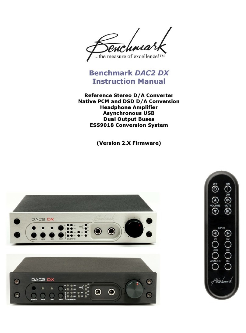
Benchmark DAC2 DX User manual
