Benchmark DAC3 B User manual

Benchmark DAC3 B
Instruction Manual
Reference Stereo
PCM and DSD D/A Converter
with
ESS9028PRO Conversion System
(Version 1.x Firmware)

Instruction Manual for DAC3 B with 1.X Firmware Page 2
Safety Information
Fuses
CAUTION: FOR CONTINUED FIRE
HAZARD PROTECTION ALWAYS REPLACE
THE FUSES WITH THE CORRECT SIZE
AND TYPE (0.5A 250 V SLO-BLO® 5 X 20
MM – LITTELFUSE® HXP218.500 OR
EQUIVALENT). THE FUSE DRAWER
INCLUDES TWO FUSES. ALWAYS
REPLACE BOTH FUSES AT THE SAME
TIME.
AC Input Voltage Range
NOTE: THE DAC3 IS EQUIPPED WITH A
UNIVERSAL POWER SUPPLY. THERE IS
NO VOLTAGE SELECTION SWITCH. AC
VOLTAGE RANGE IS 88-264 VAC, 47-63
HZ. THE PRODUCT MAY ALSO BE
OPERATED FROM DC POWER OVER A
VOLTAGE RANGE OF 125-373 VDC.
Power Cord
CAUTION: ALWAYS USE A GROUNDED
POWER CORD. THE PRODUCT IS
EQUIPPED WITH A STANDARD IEC
POWER ENTRY MODULE. USE AN IEC
POWER CORD THAT IS EQUIPPED WITH
THE APPROPRIATE CONNECTOR FOR
YOUR LOCATION. CORDS ARE AVAILABLE
FROM YOUR DEALER.
Modifications
CAUTION: DO NOT SUBSTITUTE PARTS
OR MAKE ANY MODIFICATIONS
WITHOUT THE WRITTEN APPROVAL OF
BENCHMARK MEDIA SYSTEMS, INC.
MODIFICATION MAY CREATE SAFETY
HAZARDS AND VOID THE WARRANTY.
CAUTION:CHANGES OR MODIFICATIONS
NOT EXPRESSLY APPROVED BY
BENCHMARK MEDIA SYSTEMS COULD
VOID THE USER'S AUTHORITY TO
OPERATE THE EQUIPMENT UNDER FCC
REGULATIONS.
Repairs
CAUTION: DO NOT SERVICE OR REPAIR
THIS PRODUCT UNLESS PROPERLY
QUALIFIED. ONLY A QUALIFIED
TECHNICIAN SHOULD PERFORM
REPAIRS.

Instruction Manual for DAC3 B with 1.X Firmware Page 3
Contents
Safety Information 2
Fuses 2
AC Input Voltage Range 2
Power Cord 2
Modifications 2
Repairs 2
Features 4
Introduction 5
Applications 5
DAC3 vs. DAC2 5
DAC3 vs. DAC1 5
DAC3 Technologies 5
Front Panel 8
Rear Panel 8
Quick Start Guide 9
Audio Inputs 9
Remote Control (optional) 9
Front Panel Controls 10
Front Panel Display 11
Operational Details 13
AUTO-ON Function 13
CONTROL-LOCK Function 13
Bi-directional 12V Trigger 14
HPA4, LA4 Compatibility 16
USB MODE Selection 16
High-Current Outputs 16
Driving Power Amplifiers 16
Digital Pass-Through 17
Firmware Version Identification 18
Rear Panel 19
Inputs 19
Outputs 22
AC Power-Entry and Fuse Module 23
Internal Settings 24
Jumper-Configured Options 24
Removing Top Cover 24
XLR Output Pads 25
Digital PASS-THROUGH Function 26
Rack Mounting 27
Benchmark Rack Mount Tray 27
Benchmark ½-Wide Blank Plate 27
DAC1, DAC2 and DAC3 Family History 28
DAC1 Series 28
DAC2 Series 28
DAC3 Series 29
Benchmark Technologies 30
Native DSD Conversion 30
High Headroom DSP 30
32-bit SABRE-PRO D/A System 31
Diagnostic Displays 31
Bi-Directional 12 Volt Trigger 31
Distributed Power Regulation 32
Differential Amplifiers 32
Jitter-Immune UltraLock3™ 32
Multi-Mode Asynchronous USB Audio 35
USB Driver Installation 37
Performance Graphs 42
Specifications 57
Audio Performance 57
Group Delay (Latency) 58
Digital Audio Inputs 58
Jitter Tolerance 58
Balanced Analog Outputs 59
Unbalanced Analog Outputs 59
Status Display 59
AC Power Requirements 60
Dimensions 60
Weight 60
Regulatory Compliance 61
FCC and RoHS Compliance Statements 61
FCC Notice (U.S. Only) 61
RoHS Compliant Information 61
CE Certificate of Conformity 62
Warranty Information 63
Benchmark 1-Year Warranty 63
Benchmark Extended Warranty Options 64
Notes on Warranty Repairs 64

Instruction Manual for DAC3 B with 1.X Firmware Page 4
Features
Fixed Gain Calibrated Outputs – XLR outputs are calibrated to +24 dBu at 0 dBFS (pads at 0
dB), RCA outputs are calibrated to 2 Vrms at 0 dBFS (calibration is equivalent to "HT MODE" or
"CALIBRATED MODE" on other DAC3 models)
CONTROL LOCK - Disables keypad and remote control to prevent accidental changes
Low-Impedance Passive Output Pads – 0, 10, and 20 dB – optimize output level to power
amplifiers and other downstream devices to maximize system SNR (Page 25)
SABRE PRO - 32-bit PCM D/A conversion system, four 32-bit D/A converters per channel
SABRE PRO – Native DSD D/A conversion system, four 1-bit DSD D/A converters per channel
Benchmark UltraLock3™ Jitter Attenuation System – eliminates jitter-induced distortion
High Headroom DSP - provides 3.5 dB of analog and digital headroom above 0 dBFS to
completely eliminate the clipping of intersample peaks
Multi-Mode Asynchronous USB Audio 2.0 – 24 bit/192 kHz, DSD (DoP 1.1)
Driverless Asynchronous USB Audio 1.1 – 24-bit/96 kHz
Sample Rate Display – displays the measured sample rate, and format (PCM or DSD)
Word Length Display – displays the measured word length
2 Coaxial Digital Inputs – 24-bit/192 kHz PCM, DSD (DoP 1.1)
2 Optical Digital Inputs – 24-bit/96 kHz PCM
1 Coaxial Digital Output – digital pass through from USB, Coax, and optical inputs when
function is enabled (Page 26)
2 Stereo Analog Outputs – 1 pair balanced (XLR), plus 1 pair unbalanced (RCA)
IR Remote with metal housing provides control of all functions (optional)
Automatic De-Emphasis – automatically responds to consumer pre-emphasis bit (44.1, 48
kHz)
12V Trigger I/O – bi-directional 12V trigger can act as input, output, or both (Page 14)
AUTO-ON Function - can be programmed to turn on when AC is applied (Page 13)
Power Switch – very low standby power , <0.5 W at 120 VAC
High-Efficiency Low-Noise Power Supplies – only 12-15 W, 88-264 VAC, 47-63 Hz
Meets FCC Class B and CE emissions requirements
Tested for immunity to radiated and conducted RF interference

Instruction Manual for DAC3 B with 1.X Firmware Page 5
Introduction
Applications
The DAC3 B is the ideal converter to use in
front of Benchmark's HPA4 headphone
amplifier or LA4 line amplifier. It is also ideal
for many professional studio applications. It
delivers the full performance of the flagship
DAC3 HGC, but eliminates the volume
control, the analog inputs, the mute and
polarity controls, and the headphone
amplifier.
The DAC3 B is a professional reference-grade
audio digital to analog converter with a fixed-
gain output. The DAC3 B supports 24-bit D/A
conversion of PCM at sample rates up to 192
kHz. It also supports direct conversion of 1-
bit DSD at a 2.8224 MHz sample rate. It is
designed to be very transparent and this
makes it well-suited for critical monitoring in
studio control rooms and mastering rooms.
The DAC3 B provides D/A conversion and
digital source selection. The DAC3 B is ideal
for use with the Benchmark HPA4
headphone/line amplifier or the LA4 line
amplifier. These devices provide a very high-
performance analog volume control that is a
perfect complement to the fixed-gain output
of the DAC3 B.
The fixed-gain DAC3 B has many applications
in a professional environment where a
calibrated output is required. The CONTROL
LOCK function can be enabled to prevent
accidental changes to the settings.
DAC3 vs. DAC2
The DAC3 builds upon Benchmark’s highly
successful DAC2product family. The DAC3
maintains the familiar DAC2form factor, but
adds the higher performance available from
the new ES9028PRO D/A converter. The
DAC3 offers the following improvements over
the DAC2:
•Active 2nd Harmonic Compensation
•Active 3rd Harmonic Compensation
•Lower THD
•Lower passband ripple
•Improved frequency response
•Increased Dynamic Range
•Faster PLL lock times
•Faster switching between inputs
DAC3 vs. DAC1
The DAC3 and DAC2 add these features that
are not found on the DAC1:
•Asynchronous 192kHz USB Audio 2.0
•32-bit D/A conversion system
•Word Length Display
•Sample Rate Display
•Polarity Control
•Direct DSD D/A Conversion
•-20 dB DIM
•Bi-Directional 12V Trigger
•Power Switch with Auto-On Function
•Digital Pass-Through
•High-Headroom DSP
•Additional I/O
DAC3 Technologies
4:1 Parallel Conversion Structure
The conversion system in the DAC3 achieves
a 6 dB signal to noise improvement through
the use of 4:1 summing. The ES9028PRO D/A
is an 8-channel 32-bit converter. In the
DAC3, four channels are summed in the
analog domain to form each of the two output
channels.
The 4:1 summing also improves the THD. The
non-linearities in individual conversion
channels are averaged across the four
summed channels and incoherent non-
linearities are attenuated by 6 dB.
Harmonic Compensation
The ES9028PRO has two distortion
compensation systems that independently
remove most of the 2nd and 3rd harmonic
distortion in the D/A converter. Benchmark's
ultra-clean analog output stages allow these
systems to be fully leveraged in the DAC3.

Instruction Manual for DAC3 B with 1.X Firmware Page 6
High-Headroom Digital and Analog
Processing
The DAC3 B has generous amounts of analog
and digital headroom. The analog clip point is
above 29 dBu. The digital clip point is +3.5
dBFS and is aligned to 27.5 dBu. The factory
calibration is +24 dBu at 0 dBFS. This means
that the DAC3 B has 3.5 dB of digital
headroom above 0 dBFS, and another 1.5 dB
before reaching analog clip. The digital
headroom prevents the clipping of
intersample overs. The analog headroom
allows accurate reproduction of intersample
peaks without clipping.
No Clipping of Intersample Overs
The DAC3 is one of very few D/A converters
that can accurately reproduce intersample
overs without clipping. Intersample peaks can
reach +3.01 dBFS and commonly occur many
times per second in most 44.1 kHz and 48
kHz recordings. When recordings are ripped
using lossy compression systems (such as
MP3), additional intersample overs are often
created. Most converters (including the
DAC1) produce bursts of distortion at every
occurrence of an intersample over. In
contrast, the DAC2and DAC3 converters
cleanly reproduce all intersample overs
without clipping.
Low-Noise Power Supplies
The DAC3 uses high-efficiency low-noise
power supplies. Each critical subsystem also
has at least one dedicated low-noise
regulator. The high-efficiency supplies deliver
the substantial power required by the low-
impedance circuits and the output line
drivers. A power switch is included. The
standby power consumption is less than 0.5
W when the unit is off.
Low Magnetic Emissions
The magnetic components in the DAC3 power
supplies operate at over 800 kHz. This allows
the use of very small magnetic components
that emit correspondingly small magnetic
fields. This virtually eliminates all traces of
line-frequency components in the output
spectrum of the DAC3. This also means that
the DAC3 can be placed in close proximity to
any audio component without causing
interference with the other component.
UltraLock3™ Clock System
UltraLock3™ provides the outstanding jitter
attenuation of Benchmark's UltraLock2™
system while providing virtually instantaneous
(6 ms) lock times.
Dual-Mode USB Input
The DAC3 has a USB input that can be
operated in two modes; driverless USB
Audio 1.1, and a high sample rate USB
Audio 2.0. Both use asynchronous clocking
to eliminate the USB interface as a source of
clock jitter.
Note: To provide full backward and forward
compatibility, the DAC3 uses the DAC2 USB
drivers. This prevents the need to install two
different sets of drivers. Please note that the
DAC3 USB input will be identified as
"Benchmark DAC2" in your computer control
panels. This is intentional.
Asynchronous USB Audio 2.0
The USB Audio 2.0 interface supports DSD
and 192 kHz, 24-bit PCM. No drivers are
required for Apple or Linux operating
systems. Drivers are provided for Windows
operating systems at:
BenchmarkMedia.com/drivers
Native Asynchronous USB 1.1
The DAC3 has a driverless USB Audio 1.1
mode that supports 96 kHz, 24-bit PCM with
all operating systems. This mode provides a
quick and easy connection to a wide variety of
computers and tablets without installing a
driver.

Instruction Manual for DAC3 B with 1.X Firmware Page 7
Low-Impedance Passive Attenuators
Like the DAC1 and DAC2, the DAC3 includes
low-impedance passive attenuators on the
XLR outputs. These attenuators can be
adjusted to optimize the interface with
preamplifiers, power amplifiers or powered
monitors. This optimization places the system
volume control in its best operating range.
This exclusive Benchmark feature can provide
substantial improvements in the performance
of the playback signal chain.
Native DSD Conversion
The DAC3 supports native DSD conversion.
This feature was not available on the DAC1.
DSD signals can be delivered to the USB or
Coaxial inputs in DoP 1.1 format. The DSD
signal is then routed directly to a bank of 1-
bit DSD D/A converters. Four balanced 1-bit
converters are summed together for each
balanced output.
Digital Pass-Through
The second coaxial input (D4) can be
reconfigured as a digital output. When
operating as an output, any selected digital
input is passed through to D4 without any
processing. Optical, coaxial, and USB inputs
can be passed through to the D4 connector.
This even includes special signals such as
DoP, DTS, Dolby Digital, even when these
signals cannot be decoded by the DAC3.
Bi-directional 12V Trigger
The 12 Volt trigger can be connected to other
audio components so that an entire audio
system can turn on and off in a sequenced
fashion. The DAC3 trigger I/O can be
connected to a preamplifier, power amplifier,
or both. The DAC3 will pull the trigger I/O to
12 volts DC while the DAC3 is on. If the
DAC3 is off and an external device pulls the
trigger I/O to 12 volts, the DAC3 will turn on.
Auto-On Function
The DAC3 can be programmed to
automatically turn on when AC power is
applied. (Page 13)

Instruction Manual for DAC3 B with 1.X Firmware Page 8
Front Panel
•IR Sensor
•Power Button
•Control-Lock Button and Indicator
•Input Select Buttons
•Input Indicators
•Word-Length Indicators
•Sample-Rate Indicators
Rear Panel
•Balanced Outputs
•Unbalanced Outputs
•Digital Inputs
•12V Trigger I/O
•IEC Power Entry with Fuses
Instruction Manual for DAC3 B with 1.X Firmware Page 9
Quick Start Guide
Audio Inputs
The DAC3 B features five stereo digital inputs
(2 coaxial, 2 optical, and 1 USB). The coaxial
and optical inputs accept professional (AES)
and consumer (S/PDIF) data formats at word
lengths up to 24-bits.
Tip: We recommend using the coaxial or USB
inputs for sample rates above 96 kHz. Optical
interfaces are not always reliable at sample
rates above 96 kHz.
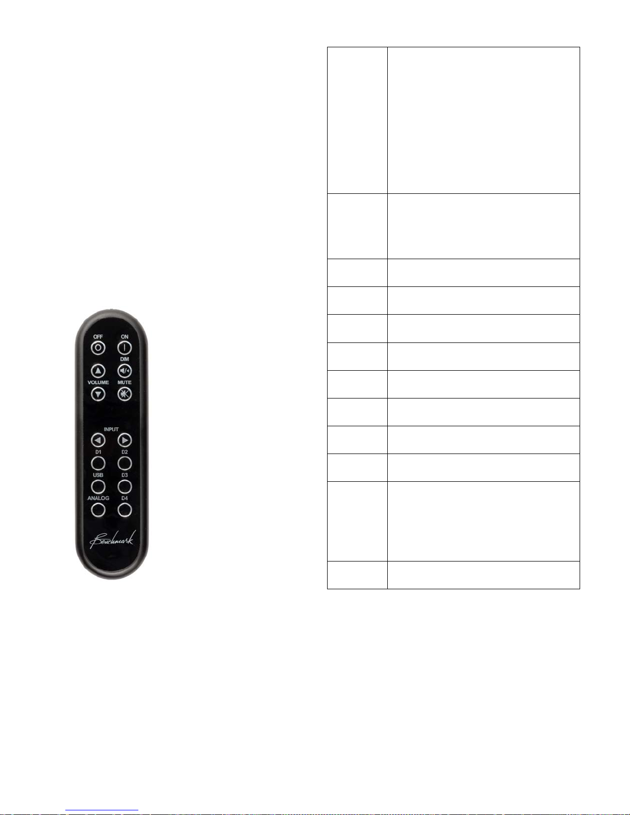
Remote Control (optional)
Tip: The remote control is designed to have a
long operating range. In most applications it
is not even necessary to point the remote
directly at the DAC3. The IR sensor is located
above the POWER button.
The chart at the right summarizes the
functions of the optional IR remote
control.
Tip: To provide system compatibility with the
Benchmark HPA4 and LA4, the DIM, MUTE,
VOLUME UP/DOWN, INPUT UP/DOWN
and ANALOG keys are not used by the
DAC3 B.
Tip: The CONTROL-LOCK button disables
the remote control and all other buttons on
the front panel.
OFF
Turns the unit off. Any devices
slaved to the 12V TRIGGER will
also turn off in a controlled
sequence.
Press and hold the OFF button for
3 seconds to force the 12V
TRIGGER off (only necessary
when another device is acting as a
TRIGGER BUS MASTER).
ON
Turns the unit on. Any devices
slaved to the 12V TRIGGER will
also turn on in a controlled
sequence.
VOLUME
Not used.
DIM
Not used.
MUTE
Not used.
INPUT
Not used.
D1
Selects optical digital input D1.
D2
Selects optical digital input D2.
D3
Selects coaxial digital input D3.
D4
Selects coaxial digital input D4.
USB
Selects USB input.
Press and hold the USB button for
3 seconds to toggle between the
USB 1.1 and USB 2.0 modes.
Analog
Not used.

Instruction Manual for DAC3 B with 1.X Firmware Page 10
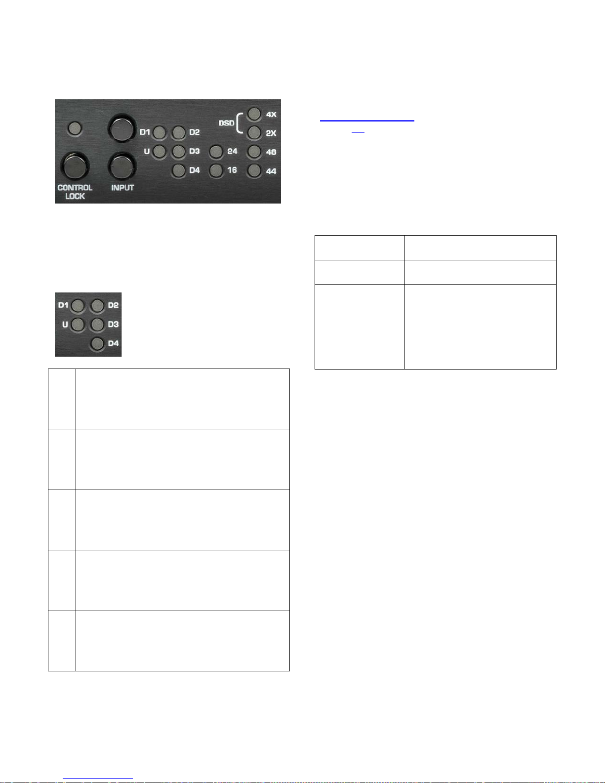
Front Panel Controls
Tip: The CONTROL-LOCK button disables
the remote control and all buttons on the
front panel. Use this function in dedicated
applications to prevent loss of audio. If you
are not using the 12V TRIGGER I/O, you
will also want to activate the AUTO-ON
feature because the POWER button is
disabled.
Tip: When AUTO-ON is enabled, a switched
AC outlet can be used to turn your system on
and off. The 12V TRIGGER I/O can be used
as a trigger output to control the power state
of additional components.
Tip: The IR remote control sensor is located
directly above the POWER button.
The chart at the right summarizes the
functions of the front-panel controls.
POWER
Turns the unit on or off. Any
devices slaved to the 12V
TRIGGER will also turn on or
off in a controlled sequence.
Starting with the unit off, press
and hold the POWER button
for 3 seconds to set the AUTO-
ON function.
Starting with the unit on, press
and hold the POWER button
for 3 seconds to clear the
AUTO-ON function.
If AUTO-ON is set, the
POWER button is disabled.
If CONTROL-LOCK is on,
press the POWER button for 3
seconds to turn the unit off.
CONTROL
LOCK
Press and hold for 3 seconds to
toggle CONTROL-LOCK on or
off.
When the CONTROL-LOCK
light is on, the front panel keys
and remote control are
disabled.
INPUT
Press to select inputs.
If CONTROL-LOCK is on, the
INPUT buttons are disabled.
Press and hold both input
buttons for 3 seconds to toggle
between USB 1.1 and USB
2.0.
Instruction Manual for DAC3 B with 1.X Firmware Page 11
Front Panel Display
There are twelve status indicator lights on the
front panel. At least one light will be
illuminated whenever power is on.
Input Indicators
The input indicators show
which input is selected.
A flashing light indicates an
error on a digital input.
U
A solid blue light indicates that the USB
input is selected and operating normally.
A blinking blue light indicates that the
input is selected but a connection to a
computer has not been established.
D1
A solid blue light indicates that optical
input D1 is selected and operating
normally. A blinking blue light indicates
that the input is selected but audio data
is not being received.
D2
A solid blue light indicates that optical
input D2 is selected and operating
normally. A blinking blue light indicates
that the input is selected but audio data
is not being received.
D3
A solid blue light indicates that coaxial
input D3 is selected and operating
normally. A blinking blue light indicates
that the input is selected but audio data
is not being received.
D4
A solid blue light indicates that coaxial
input D4 is selected and operating
normally. A blinking blue light indicates
that the input is selected but audio data
is not being received.
Note: D4 cannot be selected if the Digital
Pass Through function is enabled.
Instructions for configuring this jumper-
selected function can be found in the
Internal Settings section of this manual
(Page 26).
Input Error Codes
The input indicators flash when errors are
present on the selected digital input. There
are no error indications for analog inputs. Use
the following table to diagnose the problem:
Slow Flash
(2Hz)
No digital signal (output
muted)
Med. Flash
(7Hz)
Data transmission errors or
Non-PCM (output muted)
Rapid flashes
(14Hz)
Non-audio data is being
received (output muted)
Intermittent
flashes
Some data corruption is
occurring, converter may be
interpolating to replace
invalid samples, check the
cable.
Tip: Common causes of input errors:
•Disconnected or faulty cable
•Use of excessively long digital cables
•Use of analog cables for digital signals
•Use of optical cables for sample rates
exceeding 96 kHz
•Incompatible data type (AC3, ADAT, etc.)
•Non-audio data is being received
Instruction Manual for DAC3 B with 1.X Firmware Page 12
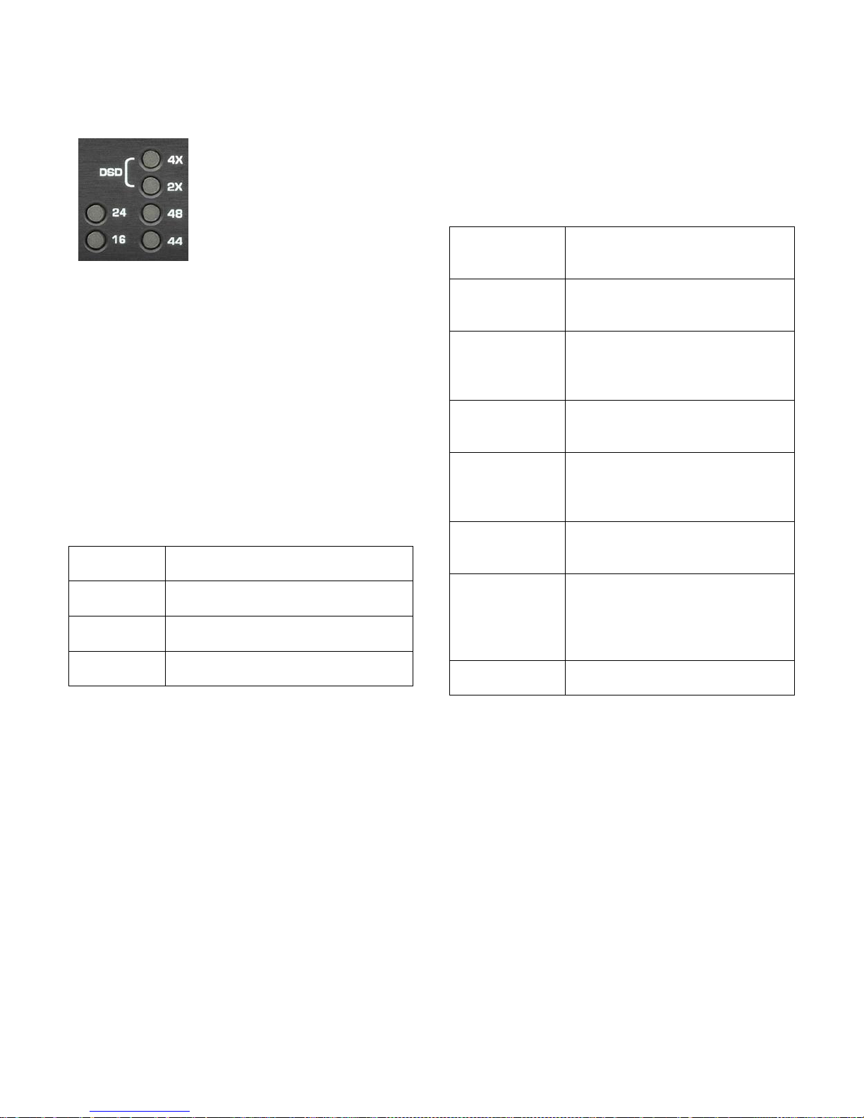
Digital Format Indicators
Two lights indicate the
measured word length of
the selected digital input.
Four lights indicate the
sample rate and format of
the selected digital input.
Tip: Computers, disk players, and streaming
devices often subject the digital signal to
sample rate conversion, changes in word
length, PCM to DSD conversions, and other
forms of digital processing that may degrade
the quality of the audio. This display makes it
easy to detect these processes.
Word Length Indicators
The 16 and 24 lights indicate the measured
word length of the selected digital input. The
DAC3 detects active data bits and displays
the results as follows:
16 Only
Measured input word length is
16 bits.
16 and 24
Measured input word length is
17 to 23 bits.
24 Only
Measured input word length is
24 bits.
Both Off
Measured input word length is
less than 16 bits.
Format indicators
The 44, 48, 2X, 4X, and DSD lights indicate
the sample rate and format of the selected
digital input as follows:
44 Only
The input format is PCM at a
sample rate of 44.1 kHz (CD
sample rate).
48 Only
The input format is PCM at a
sample rate of 48 kHz (often
used with video).
44 and 2X
The input format is PCM at a
sample rate of 88.2 kHz
(high-resolution audio
format).
48 and 2X
The input format is PCM at a
sample rate of 96 kHz (high-
resolution audio format).
44 and 4X
The input format is PCM at a
sample rate of 176.4 kHz
(high-resolution audio
format).
48 and 4X
The input format is PCM at a
sample rate of 192 kHz (high-
resolution audio format).
DSD
(4x and 2X)
The input format is 1-bit DSD
at a sample rate of 2.8224
MHz (high-resolution audio
format). Note: DSD must be
streamed in DoP format.
All Off
Digital signal is not present or
is not in a supported format.

Instruction Manual for DAC3 B with 1.X Firmware Page 13
Operational Details
AUTO-ON Function
The DAC3 can be programmed to
automatically turn on whenever AC power is
applied. This function allows automation using
switched AC outlets. When AUTO-ON is
enabled, the DAC3 cannot be turned off
without removing AC power.
The AUTO-ON function is programmed by
pressing and holding the POWER button on
the front panel for three seconds. This
function cannot be programmed from the
remote control. This limitation prevents
accidental access to this special feature.
Tip: The AUTO-ON function cannot be
changed if the CONTROL-LOCK is on. Turn
the CONTROL-LOCK off before attempting to
change the AUTO-ON function.
Enabling AUTO-ON
Starting with the DAC3 off, press and hold
the POWER button for 3 seconds.
If AUTO-ON has been successfully enabled,
the unit cannot be turned off using the
POWER button or the OFF button on the
remote.
Disabling AUTO-ON
Starting with the DAC3 on, press and hold
the POWER button for 3 seconds. At the end
of 3 seconds the DAC3 will power down if the
AUTO-ON mode has been successfully
disabled.
CONTROL-LOCK Function
The CONTROL-LOCK function
disables the remote control and
all buttons on the front panel.
Use the CONTROL-LOCK
function when the DAC3 will be
used in a dedicated application
using just one digital input. This
feature prevents accidental loss
of audio in these dedicated applications.
Controls are locked when the CONTROL-
LOCK light is on.
Press the CONTROL-LOCK button for 3
seconds to toggle this function on or off.
Tip: If CONTROL-LOCK is on, but AUTO-ON
is off, the unit can be powered down by
pressing and holding the POWER button for 3
seconds. This turns the unit off, but does not
turn off the CONTROL-LOCK function.

Instruction Manual for DAC3 B with 1.X Firmware Page 14
Bi-directional 12V Trigger
Benchmark has
reinvented the 12
volt trigger by adding
bi-directional
signaling. The trigger
connection on the
DAC3 can be used as
an input, an output, or both. It is compatible
with any common 12 volt trigger input or
output. The 12V TRIGGER I/O can be used
to turn other audio components on when the
DAC3 turns on. The DAC3 can also turn on
and off in response to other connected
components. The Benchmark bi-directional
12V Trigger is compatible with virtually all
trigger systems.
The 12V TRIGGER I/O can be connected to
the trigger input or output ports on a
preamplifier, power amplifier, or both.
The DAC3 can send a 12 Volt DC trigger
signal to start other components in the
system, or it can wake up in response to an
externally generated trigger signal. The DAC3
automatically configures its trigger I/O port
as an input (slave) or output (master).
Trigger Output (DAC3 is Master)
When the DAC3 is turned on using the
POWER button (on the front panel), or the
ON button (on the remote), the DAC3
configures itself as a trigger master and will
drive the 12V TRIGGER I/O to 12 volts DC
and hold it there while the DAC3 is on. The
trigger output signal generated by the DAC3
is delayed so that the DAC3 can stabilize
before downstream devices (such as power
amplifiers) turn on. When powering down, the
DAC3 will mute before allowing the trigger
line to drop low. The DAC3 keeps the internal
power supplies running for 10 seconds after
dropping the trigger. This delay gives other
triggered components ample time to mute
and shut down.
If the AUTO-ON function is enabled, the
DAC3 will automatically turn on when AC
power is applied, configure itself as a trigger
master, and ignore any external signaling on
the 12V TRIGGER I/O line. In AUTO-ON
mode, the DAC3 will always drive the 12V
TRIGGER I/O line to 12 V (after a short
start-up delay).
Trigger Input - (DAC3 is Slave)
If the DAC3 is off and an external device
pulls the trigger I/O to 12 volts, the DAC3
will configure itself as a trigger slave and will
follow the actions of the trigger input. The
DAC3 will then turn off when the external
device stops sending the 12 V trigger.
Typical Trigger Applications
In most systems, the 12V TRIGGER will be
used to connect the DAC3 to one other
device. The DAC3 can be connected to the
first trigger input at the beginning of a trigger
chain, or it can be connected to the last
trigger output at the end of the chain (less
common).
Typical trigger applications:
•DAC3 B →Preamplifier →Amplifier
oDAC3 B →LA4 →AHB2
•DAC3 B →Headphone Amplifier
oDAC3 B →HPA4
•DAC3 B →Amplifier
oDAC3 B →AHB2
The Benchmark bi-directional trigger system
also supports multiple trigger ports wired
together on a bus.
A group of Benchmark trigger ports can be
connected to a group of non-Benchmark
trigger input ports to form a single trigger
bus. A bus should never be connected to
more than one non-Benchmark trigger output
port. If an output port is connected to the
bus, this device should be used to start the
audio system.
A 3.5 mm (1/8") TRS "Y" cable can be used to
split the trigger output of the DAC3 to feed
more than one trigger input.

Instruction Manual for DAC3 B with 1.X Firmware Page 15
Benchmark AHB2 power amplifiers have two
trigger I/O ports that are wired in parallel.
This makes it easy to connect more than one
power amplifier to a trigger bus (without the
use of a "Y" cord). Connect a trigger cable
between the DAC3 and the first amplifier.
Use another trigger cable to connect this
amplifier to the next amplifier. Any number of
Benchmark amplifiers can be added to the
trigger bus. The DAC3 will turn on first, and
after a delay, all of the amplifiers will turn on
together.
Bi-Directional Trigger Applications
Benchmark products support bi-directional
communications over a trigger bus. Any
Benchmark product connected to the bus can
turn the entire system on or off. Because of
the bi-directional design, any power button on
a Benchmark DAC3 or AHB2 can be used to
start or stop the system.
The Benchmark device that starts the system
will become the trigger master. If the trigger
master is turned off, all slave devices will
follow. If a slave device is turned off, all other
devices will stay on.
If the DAC3 is used to turn the system on,
any connected AHB2 amplifiers will become
slave devices and they can be turned off
without shutting down the DAC3.
Slave devices can force the entire trigger bus
to shut down if the POWER button or OFF
button is pressed and held for 3 seconds.
Tip: Press and hold the POWER button on
any Benchmark device for 3 seconds to force
a shutdown of the entire trigger-connected
system.
Trigger Specifications
The Benchmark 12V TRIGGER I/O has a
wide operating range to allow interfacing with
most other DC trigger systems. It should only
be used with trigger inputs that are designed
to tolerate 12 VDC.
•12 VDC 200 mA current-limited output
•Input responds to 3.3 V logic and
higher
•Maximum input voltage = 30 VDC
•Maximum reverse input voltage = -0.3
VDC
•Input Impedance = 20 k Ohms
•1/8" (3.5 mm) TRS jack
•Tip = 12 Volt Trigger I/O
•Ring = no connection
•Sleeve = chassis ground

Instruction Manual for DAC3 B with 1.X Firmware Page 16
HPA4, LA4 Compatibility
The DAC3 B is designed to work seamlessly
with Benchmark line amplifiers (such as the
HPA4 and LA4).
The line amplifier will control the system
volume and analog input switching. The
DAC3 B will be used to select the digital
inputs. Both are controlled from a single
Benchmark remote control.
USB MODE Selection
The DAC3 supports two USB MODES:
•USB Audio 1.1 mode - up to 24 bits
at 96 kHz
•USB Audio 2.0 mode - up to 24 bits
at 192 kHz plus DSD in DoP 1.1
format
Caution: Close all USB audio playback
applications before changing the USB MODE.
If an audio application is playing while the
USB MODE is changed, the audio application
may freeze. Avoid any unnecessary switching
between USB MODES. Rapid switching
between modes can confuse some operating
systems.
Note: The computer and DAC3 must be
connected and both must be on before the
USB MODE can be changed.
To change the USB MODE, press and hold
the USB button on the remote control for 3
seconds. If a remote control is not available,
simultaneously press and hold both INPUT
buttons on the front panel for 3 seconds.
Tip: The 4X or 2X lamp will flash once every
time the USB input is selected. This flash
provides a convenient indication of the
current USB MODE. A flash of the 4X lamp
indicates that the unit is in USB Audio 2.0
mode. A flash of the 2X lamp indicates that
the unit is in USB Audio 1.1 mode.
High-Current Outputs
The RCA and XLR outputs on the DAC3 B
are equipped with low-impedance high-
current drivers. These robust outputs are well
equipped to drive a wide variety of input
impedances. The DAC3 B outputs remain
clean when driving inputs that present
difficult loads (high input capacitance and/or
low input impedance).
The XLR outputs on the DAC3 B are
equipped with jumper-configured passive low-
impedance output pads. These pads can be
set to an attenuation of 0 dB (pad off), 10
dB, or 20 dB. The pads should be used to
match the output level of the DAC3 B to the
input sensitivity of the downstream device.
Tip: In most applications we recommend
placing a Benchmark HPA4 or LA4 line
amplifier between the DAC3 B and the power
amplifier. These Benchmark line amplifiers
will optimize the analog interface between the
DAC3 and the power amplifier while providing
a stepped relay gain control with exceedingly
low THD and noise. The HPA4 or LA4
provide a transparent path between the
DAC3 B and a power amplifier.
Driving Power Amplifiers
If the system volume is being controlled
digitally by an upstream device, the DAC3 B
can be connected directly to an audio power
amplifier or a set of powered monitors. This
direct connection provides a clean path
between the DAC3 B and the amplifier, but it
is important to match the signal levels
between the DAC3 B and the power amplifier
in order to prevent excessive use of the
upstream digital volume control.
The XLR outputs are equipped with adjustable
pads that can be used to optimize the system
gain structure in order to maximize the
system noise performance.
Most power amplifiers and powered monitors
will require the use of the 10 dB or 20 dB

Instruction Manual for DAC3 B with 1.X Firmware Page 17
pads. Use the 0 dB setting when driving a
Benchmark AHB2 power amplifier.
Tip: The Benchmark AHB2 power amplifier
has a unique low-gain topology that allows it
to accept full studio-level input signals. This
high-level interconnection provides a very
low-noise connection between the DAC3 and
the AHB2. Set the input SENSITIVITY
switch on the AHB2 to 22 dBu (all the way
down). This places the AHB2 full-power
output point at an input level of 22 dBu. This
level is exactly 2 dB lower than the calibrated
output level of the DAC3 B (when the pads
are set to 0 dB). This configuration optimizes
the gain-staging between the DAC3 and the
AHB2.
Tip:If you are using a direct connection
between a DAC3 B and a non-Benchmark
power amplifier, the XLR pads should be set
so that a normal listening level is reached
when the system volume control is near its
maximum setting. This will optimize the gain-
staging between the DAC3 B and your power
amplifier.
Tip: Increase the pad setting if a comfortable
listening level is reached while the system
volume control is well below maximum.
Tip: Decrease the pad setting if a comfortable
listening level cannot be reached when the
system volume control is at maximum.
Instructions for setting the XLR pad jumpers
are detailed in the Internal Settings section
of this manual. The DAC3 B is shipped with
the XLR pads disabled (set to 0 dB). No
adjustments will be necessary if you will be
using a Benchmark AHB2 power amplifier or
Benchmark line amplifier.
Digital Pass-Through
The second coaxial input (D4) can be
reconfigured as a digital output. When
operating as an output, any selected digital
input is passed through to D4 without any
processing.
Optical, coaxial, and USB inputs (U, D1, D2
and D3) can be passed through to the D4
connector. The signals are buffered but are
not processed in any way. For this reason,
any data format can be passed through to the
D4 connector, even when these formats
cannot be decoded by the DAC3. Surround
formats, such as DTS, Dolby Digital, cannot
be decoded by the DAC3, but they can be
passed to a surround system using the digital
pass-through function.
The digital pass-through can also be used to
provide the following digital signal
conversions:
•Optical to Coaxial
•USB to Coaxial
•Coaxial to Coaxial (buffering)
DoP encapsulated DSD can also be passed
through D4. DSD files on a computer can be
sent in DoP to the USB input on the DAC3.
The USB input can be routed to coaxial
output D4. This output can be recorded by
any 24-bit, 176.4 kHz digital recorder with a
coaxial input. The PCM digital recorder can
then be used to play the DSD recordings.

Instruction Manual for DAC3 B with 1.X Firmware Page 18
Firmware Version Identification
The firmware version is displayed during the
lamp test while the DAC3 B is turning on. At
least one lamp in the INPUT INDICATOR
will flash rapidly while the remaining lamps
will be on. The flashing lamps identify the
firmware version. The values of each lamp
are shown in this chart. Add the values of all
flashing lamps to determine the version
number. If no lamp flashes in the second
column, the second digit is a 0.
Digit 1
Digit 2
2
D1
D2
.4
1
U
D3
.2
D4
.1
Example 1: The Ulamp is the only lamp that
flashes. The firmware version is 1.0.
Example 2: The U and D4 lamps flash. The
firmware version is 1.1.
Example 3: The D1 lamp is the only lamp
that flashes. The firmware version is 2.0.

Instruction Manual for DAC3 B with 1.X Firmware Page 19
Rear Panel
Inputs
There are five stereo digital inputs on the
DAC3 B:
•USB - USB Audio 1.1 or 2.0 Input
•D1 - Optical Digital Input
•D2 - Optical Digital Input
•D3 - Coaxial Digital Input
•D4 - Coaxial Digital Input or Output*
These inputs are selected using the INPUT
buttons on the front-panel or on the remote-
control.
*D4 can be jumper-configured as a digital
PASS-THROUGH output. When enabled, the
selected digital input will be routed to the
internal D/A converter and to output D4. The
selected input will be buffered and sent to
output D4 even if the format cannot be
decoded by the DAC3 B.
The digital inputs support PCM stereo
AES/EBU and SPDIF digital formats. Maximum
word length is 24-bits. Maximum sample rate
is 192kHz.
The digital inputs also support DSD stereo at
a sample rate of 2.8224 MHz using DoP 1.1
encapsulation.
The USB input has two operating modes:
•USB Audio 1.1 - PCM up to 24-bits at
96 kHz
•USB Audio 2.0 - PCM up to 24-bits at
192 kHz and DSD (DoP 1.1 format)
Caution:The optical inputs (D1 and D2) are
not recommended for DSD or for sample
rates above 96 kHz. Optical connections may
be unreliable at sample rates above 96 kHz.
Tip: The DAC3 B will not decode
multichannel digital formats such as AC3, and
Dolby Digital. The audio will mute and the
INPUT INDICATORS will flash whenever an
incompatible format is connected to the
selected digital input. If the PASS-THROUGH
mode is enabled, these multichannel formats
can be sent to a surround processor using
connector D4 as a digital output.
Caution: The 12V TRIGGER I/O is not an
audio connection! This is a 12V DC connection
for synchronizing the on and off sequencing of
an entire audio system.

Instruction Manual for DAC3 B with 1.X Firmware Page 20
Digital Inputs - Overview
All of the digital inputs on the DAC3 B use
Benchmark's UltraLock3™ system to remove
virtually all of the interface jitter. The result is
that all digital inputs deliver identical audio
performance. The USB, optical, and coaxial
digital inputs will all sound identical if they
receive identical data.
Computer Input – USB
The USB input accepts a Type-B male USB
connector. A Type-A to Type-B USB cable is
provided with the DAC3 B. The USB cable
connects the DAC3 B directly to a computer’s
USB output.
The USB input supports 44.1, 48, 88.2, 96,
176.4, and 192 kHz PCM sample rates at
word lengths up to 24-bits. The USB input
also accepts DSD in DoP 1.1 format.
The DAC3 B can be configured as a USB
Audio 1.1 or USB Audio 2.0 device. Press
and hold the USB button on the REMOTE for
three seconds to toggle the USB MODE. If a
remote is not available, simultaneously press
and hold both input buttons on the front
panel for three seconds.
The USB AUDIO 1.1 mode does not require
the installation of a driver. It allows a quick
driverless connection to windows machines
when playing sample rates of 96 kHz or less.
In this mode, Windows machines can begin
streaming audio within seconds after the
DAC3 B is connected for the first time. No
software or hardware configuration is usually
required.
USB Audio 2.0 is required for DSD and for
all PCM sample rates exceeding 96 kHz.
Windows computers require a driver to
support the USB Audio 2.0 mode.
The USB Audio 1.1 mode was tested for
compatibility with Windows XP, Vista, 7, 8
and 10, Mac OS X, and iPads using the 30-pin
to USB Camera Kit. No driver installation is
required for any of these systems when
operating in USB Audio 1.1 mode.
The USB Audio 2.0 mode was tested for
compatibility with Windows XP, Vista, 7, 8
and 10 (driver installation is required for all
Windows versions). It was also tested for
compatibility with Mac OS X starting with
version 10.6 (operation is driverless for all OS
X versions).
Optical Digital Inputs - D1 and D2
The optical input connectors (D1 and D2) are
commonly known as TOSLINK connectors.
The TOSLINK optical connectors used on the
DAC3 B are designed to work well at sample
rates up to 96 kHz. Maximum word length is
24-bits. All sample rates between 28 and 96
kHz are supported. The optical inputs may be
unreliable at sample rates above 96 kHz. The
optical inputs will accept professional
AES/EBU data formats or consumer S/PDIF
data formats.
Tip: The optical inputs include dust caps.
Keep these in place if the input is not being
used.
Coaxial Digital Inputs - D3 and D4
The coaxial digital inputs (D3 and D4) use
female RCA connectors. The input impedance
is 75 Ohms. Maximum word length is 24-bits.
All sample rates between 28 and 195 kHz are
supported. The coaxial digital inputs will
accept professional AES/EBU data formats or
consumer S/PDIF data formats. The coaxial
inputs also accept DSD in DoP 1.1 format.
The coaxial digital inputs are DC isolated,
current limited, and diode protected. The RCA
body is bonded directly to the chassis to
prevent currents in the internal ground
system. This direct bonding also maximizes
RF shielding.
Caution:Use 75-Ohm coaxial cables for
digital audio connections D3 and D4. Digital
interfaces require the use of matched
impedances. Do not use 50-Ohm coaxial
cables, twisted pair cables, or any non-coaxial
cables for digital audio. The digital inputs may
not function, or may be unreliable if the
incorrect cable is used.
Table of contents
Other Benchmark Media Converter manuals

Benchmark
Benchmark DAC3 HGC Quick start guide

Benchmark
Benchmark DAC1 HDR User manual

Benchmark
Benchmark DAC2 DX User manual

Benchmark
Benchmark DAC2 DX User manual

Benchmark
Benchmark DAC1 HDR User manual

Benchmark
Benchmark DAC1 PRE User manual

Benchmark
Benchmark AD2402-96 User manual

Benchmark
Benchmark DAC1 USB User manual

Benchmark
Benchmark ADC16 User manual

Benchmark
Benchmark ADC1 USB User manual


