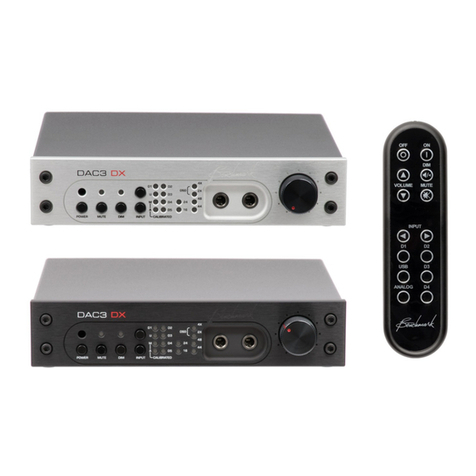
Benchmark DAC2 DX User manual

Benchmark
DAC2 DX
Instruction Manual
Reference Stereo D/A Converter
Native PCM and DSD Conversion
Headphone Amplifier
Dual Output Buses
Asynchronous USB

DAC2 DX Instruction Manual Rev B Page 2
Contents
Safety Information 4
Fuses 4
Voltage Selection 4
Power Cord 4
Modifications 4
Repairs 4
Quick Start Guide 5
Rear Panel 5
Front Panel 6
Control Functions 8
Applications 9
Professional Applications 9
HI-FI Applications 9
Computer Sound Card Elimination 9
Standalone Headphone Amplifier 9
DAC2 vs. DAC1 10
New Features 10
Performance Improvements 10
DAC2 DX Features 11
Feature List 11
Special DAC2 DX Features 12
Feature Details 13
DAC1 and DAC2 Product History16
DAC1 Series History 16
DAC2 Series History 17
Digital Inputs 18
Input Formats 18
Limitations of Optical Inputs 18
Consistent Performance 18
USB - Computer Input 19
D1 and D2 - Optical Digital Inputs 20
D3 - AES XLR Digital Input 20
D4 and D5 - Coaxial Digital Inputs 20
D5 - Coaxial Digital Output 21
AES XLR to Coaxial Adapters 21
Analog Outputs 22
Main Output Bus 22
AUX Output Bus 22
Balanced Analog XLR Line Outputs 22
XLR Wiring 23
Unbalanced Analog RCA Line Outputs 23
AC Power-Entry and Fuses 24
Fuses 24
Voltage Selection 24
Power Cord 24
Internal Settings 25
Jumper-Configured Options 25
Removing Top Cover 25
XLR Output Pads 26
Digital Pass-Through Function 30
Rackmounting Options 31
Rackmount Version of the DAC2 DX 31
Connector Block 31
Premium ½-Wide Blank Rack Panel 32
Black ½-Wide Rack Panel 32
Universal Rack Adapter Tray 32
Rackmounting Example 33
Benchmark Technologies 34
Hybrid Gain Control™34
Native DSD Conversion 34
Multi-Mode Asynchronous AdvancedUSB
Audio™34
Jitter-Immune UltraLock2™35
High Head-Room DSP 35
32-bit SABRE Conversion System 35
Diagnostic Display 35
Bi-Directional 12 Volt Trigger 35
Distributed Power Regulation 35
HPA2™Headphone Amplifier 36
Differential Amplifiers 36
UltraLock2™Clock System 36
USB Audio System Setup 40
USB Driver Installation - Windows XP,
Vista, 7 41
Performance Graphs - DAC2
Series 47
Specifications 63
Audio Performance 63
Group Delay (Latency) 64
Digital Audio Inputs 64
Jitter Tolerance 65
Balanced Analog Outputs 66

DAC2 DX Instruction Manual Rev B Page 3
Unbalanced Analog Outputs 66
HPA2TM Headphone Outputs 67
Status Display 67
AC Power Requirements 68
Dimensions 68
Weight 68
Regulatory Compliance 69
FCC and RoHS Compliance Statements 69
FCC Notice (U.S. Only) 69
RoHS Compliance Information 69
CE Certificate of Conformity 70
Warranty Information 71
Benchmark 1 Year Warranty 71
The Benchmark 1 Year Warranty 71
Benchmark Extended Warranty 72
The Benchmark Extended 5* Year
Warranty 72
The Benchmark’s Extended 2** Year
International Warranty 72
Notes on Warranty Repairs 72

DAC2 DX Instruction Manual Rev B Page 4
Safety Information
Fuses
CAUTION: FOR CONTINUED FIRE HAZARD
PROTECTION ALWAYS REPLACE THE FUSES
WITH THE CORRECT SIZE AND TYPE (0.5A
250 V SLO-BLO® 5 X 20 MM –LITTELFUSE®
HXP218.500 OR EQUIVALENT). THE FUSE
DRAWER INCLUDES TWO FUSES. ALWAYS
REPLACE BOTH FUSES AT THE SAME TIME.
Voltage Selection
THE DAC2 IS EQUIPPED WITH A UNIVERSAL
POWER SUPPLY. THERE IS NO VOLTAGE
SELECTION SWITCH. AC VOLTAGE RANGE IS
88-264 VAC, 50-60 HZ. THE PRODUCT MAY
ALSO BE OPERATED FROM DC POWER OVER
A VOLTAGE RANGE OF 125-373 VDC.
Power Cord
CAUTION: ALWAYS USE A GROUNDED
POWER CORD. THE PRODUCT IS EQUIPPED
WITH A STANDARD IEC POWER ENTRY
MODULE. USE AN IEC POWER CORD THAT IS
EQUIPPED WITH THE APPROPRIATE
CONNECTOR FOR YOUR LOCATION. CORDS
ARE AVAILABLE FROM YOUR DEALER.
Modifications
CAUTION: DO NOT SUBSTITUTE PARTS OR
MAKE ANY MODIFICATIONS WITHOUT THE
WRITTEN APPROVAL OF BENCHMARK MEDIA
SYSTEMS, INC. MODIFICATION MAY CREATE
SAFETY HAZARDS AND WILL VOID THE
WARRANTY.
NOTICE: CHANGES OR MODIFICATIONS NOT
EXPRESSLY APPROVED BY BENCHMARK
MEDIA SYSTEMS COULD VOID THE USER'S
AUTHORITY TO OPERATE THE EQUIPMENT
UNDER FCC REGULATIONS.
Repairs
CAUTION: DO NOT SERVICE OR REPAIR
THIS PRODUCT UNLESS PROPERLY
QUALIFIED. ONLY A QUALIFIED TECHNICIAN
SHOULD PERFORM REPAIRS.

DAC2 DX Instruction Manual Rev B Page 5
Quick Start Guide
Rear Panel
Analog Audio Outputs
The DAC2 DX has three stereo analog outputs driven from two separate output busses. By default
both busses are controlled from the front panel volume control. Either or both busses may be
programmed to BYPASS the volume control. When an output bus is set to BYPASS, the output
level is set to a calibrated maximum level. The XLR outputs can deliver +24 dBu. The RCA outputs
can deliver 2 Vrms (8.2 dBu).
The MAIN output bus drives a pair of balanced XLR outputs and a pair of unbalanced RCA outputs.
The AUX output bus drives a pair of unbalanced RCA outputs.
Digital Audio Inputs
The DAC2 DX has six stereo digital inputs (1 USB, 1 AES XLR, 2 optical and 2 coaxial). The XLR,
coaxial and optical inputs accept professional (AES) and consumer (S/PDIF) data formats at word
lengths up to 24-bits. The optical inputs are limited to 96 kHz sample rates. All other inputs
support sample rates up to 192 kHz.
12V Trigger I/O
The 1/8”TRS jack on the rear panel is a bi-directional 12V trigger connection to enable power
sequencing between the DAC2 DX and other audio devices in the signal chain. If the tip of the TRS
connector is driven to 12 volts, the DAC2 DX will turn on. If the DAC2 DX is turned on locally, the
DAC2 DX will drive the tip of the TRS connector to 12 V to turn on other linked devices.
AC Power Input
The DAC2 DX is equipped with a universal power supply. There is no voltage selection switch. AC
voltage range is 88-264 VAC, 50-60 HZ. The fuse drawer contains two fuses, always use exact
replacements.

DAC2 DX Instruction Manual Rev B Page 6
Front Panel
Power Switch
Press once to turn on. Press once to turn off.
IR Receiver
The IR receiver for the remote control is located directly above the power switch. Do not block this
opening.
MUTE Switch and Light
Press to MUTE all outputs. Press again to release.
DIM Switch and Light
Press to reduce the level of all outputs by 20 dB. Press again to release.
Input Selector Switches and Lights
Press the INPUT buttons to select a digital input.
If an input light is on, the corresponding input is selected and operating normally:
·U- USB digital audio input
·D1 - First optical digital audio input
·D2 - Second optical digital audio input
·D3 - XLR digital audio input
·D4 - First coaxial digital audio input
·D5 - Second coaxial digital audio input
If an input light is flashing, the selected input is not connected or is not working properly:
·Slow Flashes (2 flashes/second) –No input signal, transmission errors, or Non-PCM
·Rapid flashes –Non-audio (input is flagged as data)
·Intermittent flashes –Invalid sample (v-bit), unreliable connection

DAC2 DX Instruction Manual Rev B Page 7
Output Calibration Lights
If a CALIBRATION light is on, the corresponding output bus is set to the calibrated maximum
output level and the volume control is bypassed (BYPASS mode).
If a CALIBRATION light is flashing slowly, the corresponding output bus is set to BYPASS mode,
but the output is muted or dimmed.
·A- AUX analog output bus is in BYPASS
·M–MAIN analog output bus is in BYPASS
NOTE: If a bus is not in bypass mode, the corresponding CALIBRATION light will flash rapidly
when the volume control is adjusted. This feature shows which busses are being adjusted.
Word Length Display
The DAC2 monitors bit activity to determine the input word length. This gives an accurate
indication even when status bits are set incorrectly.
·24 –The word length is 24-bits.
·16 –The word length is 16-bits.
·16 & 24 –The word length is 17 to 23 bits.
·None - No input, DSD, or word length less than 16 bits.
Sample Rate Display
The DAC2 measures the incoming sample rate and uses 4 lights to indicate the rate and format.
·44.1 –Sample rate is 44.1 kHz
·48 –Sample rate is 48 kHz
·44.1 & 2X –Sample rate is 88.2 kHz
·48 & 2X –Sample rate is 96 kHz
·44.1 & 4X –Sample rate is 176.4 kHz
·48 & 4X –Sample rate is 192 kHz
·2X & 4X –DSD
Headphone Jacks
The headphone jacks are driven by Benchmark’s “zero-Ohm”HPA2™headphone power amplifier.
Both jacks can be used simultaneously. Both jacks are equipped with switches that can be
programmed to mute the MAIN audio output bus when headphones are inserted. By default, the
left headphone jack is programmed to mute the MAIN output bus while the right jack will not mute
the audio. Internal jumpers can be moved to enable or disable the headphone switches. Other
internal jumpers can be moved to adjust the headphone gain range.
Volume Control
The volume control is a motor-driven rotary potentiometer. The position of the control sets the 32-
bit digital attenuation. Audio does not pass through the potentiometer.

DAC2 DX Instruction Manual Rev B Page 8
Control Functions
All DAC2 DX functions can be controlled from the
IR remote control or from the front panel. In most
cases, operation is identical (see table to the right
for a summary of front panel and remote control
functions).
OFF
(remote only)
Press once to turn the unit off.
* Press and hold to turn off all devices connected to the
12V TRIGGER.
ON
(remote only)
Press once to turn the unit on.
* If the unit is already on, pressing ON will cancel MUTE
and DIM.
POWER
(front panel
only)
Press once to turn the unit on or off.
* Press and hold POWER to turn off all devices
connected via the 12V TRIGGER.
VOLUME
U/D
(remote only)
Press and hold to tu
rn volume up or down.
* VOLUME UP will cancel MUTE.
DIM
Press once to toggle the
-
20 dB
DIM
function.
*DIM will cancel MUTE.
* Press and hold DIM for 10 seconds to toggle the AUX
bus VOLUME CONTROL BYPASS function.
MUTE
Press once to toggle the
MUTE
function.
* Press and hold MUTE for 10 seconds to toggle the
MAIN bus VOLUME CONTROL BYPASS function.
INPUT
U/D
Press to change the input.
* Press and hold both front panel INPUT buttons while
computer is connected to toggle between USB 2.0 and
USB 1.1.
USB
Press to select
USB
digital input.
* Press and hold remote USB button while computer is
connected to toggle between USB 2.0 and USB 1.1.
D1
Press to select 1st optical input
(remote only)
.
D2
Press to select 2nd optical input
(remote only)
.
D3
Press to select digital XLR input
(remote only)
.
D4
Press to select 1st coaxial input
(remote only)
.
D5
Press to selec
t 2st coaxial input if enabled (remote only)
.
ANALOG
Not used on
DAC2 DX
(no analog inputs)

DAC2 DX Instruction Manual Rev B Page 9
Applications
The DAC2 DX is a professional reference-grade digital to analog converter with two independent
analog output busses. It includes Benchmark's reference-quality HPA2™headphone amplifier,
Benchmark's hybrid gain control system, and Benchmark's UltraLock2™jitter attenuation system.
The DAC2 DX is designed to connect directly to power amplifiers and powered monitors. It is also
capable of delivering +24 dBu studio interface levels.
The DAC2 DX is available with an optional IR remote control which makes it equally well-suited for
home applications. In a home Hi-Fi system, the DAC2 DX provides digital source selection, volume
control, and direct drive to the power amplifier. The DAC2 DX is the only component required
between digital sources and the power amplifier.
The DAC2 DX has 6 digital inputs, 2 headphone outputs, a volume control, and 3 sets of analog
outputs. It supports D/A conversion of PCM sample rates up to 192 kHz, as well as direct DSD
conversion.
Professional Applications
The DAC2 DX is designed for maximum transparency and purity. The sonic integrity of the DAC2 DX
makes it well suited for critical playback in recording studio control rooms and mastering rooms. It
includes features that are targeted at the needs of the audio professional.
HI-FI Applications
The versatility and performance of the DAC2 DX also makes it an asset to any high-end audiophile
system. Digital signal sources may include HDTV, DVD, digital cable, music servers, digital radio,
portable devices, etc. In a Hi-Fi system, the DAC2 DX replaces the low-performance D/A converters
that are built into these low-cost devices.
Computer Sound Card Elimination
Benchmark’s Multi-Mode Asynchronous USB™interface makes the DAC2 an ideal output device
for computer-based media playback, including: home media servers, digital audio workstations,
desktop audio editing applications, and computer-based radio broadcast systems.
Standalone Headphone Amplifier
The “zero-Ohm”HPA2™headphone amplifier delivers reference-quality performance. The full
performance of the DAC2 is delivered to the headphones. Difficult loads are driven with ease.

DAC2 DX Instruction Manual Rev B Page 10
DAC2 vs. DAC1
The DAC2 series builds upon Benchmark’s highly successful DAC1 product family. Every DAC1
subsystem has been redesigned and upgraded to achieve higher performance. The DAC2 includes
an updated version of Benchmark's highly-effective UltraLock™jitter-attenuation system.
New Features
The DAC2 series introduced new features that add improve the listening experience while
extending the versatility of the product.
The DAC2 series introduced the following features:
·Native DSD conversion
·Asynchronous USB 2.0
·Asynchronous USB 1.1
·Volume-control bypass
·Digital pass-through
·Word-length display
·Sample-rate display
·Bi-directional 12V trigger
·More I/O than DAC1 Series
Performance Improvements
Lower Noise than the DAC1
An array of balanced 32-bit digital-to-analog audio converters are summed together to form each
balanced output channel. The summing reduces noise. The result is that the DAC2 is about 10 dB
quieter than the DAC1. Low-level musical details are faithfully reproduced over a breathtakingly
quiet noise floor.
Lower Distortion than the DAC1
Benchmark’s DAC1 converters are known for their very low distortion (THD and IMD). But, the
DAC2 sets new benchmarks for clean and transparent musical reproduction. The DAC2 is designed
to provide the cleanest possible path from digital to analog.
Lower Power Consumption than the DAC1
The DAC2 complies with the latest international environmental regulations and consumes less than
0.5 W when turned off. The unit runs cool while providing substantial power to the headphone and
output drivers. Power can be turned on or off from the front panel, from the remote control, or
from the 12V trigger I/O port.

DAC2 DX Instruction Manual Rev B Page 11
DAC2 DX Features
Feature List
ŸHGC™(Hybrid Gain Control) –combines a motor-driven rotary control and a 32-bit digital
attenuator with passive analog attenuators, to achieve state-of-the-art performance
ŸSABRE ES9018 - 32-bit PCM D/A conversion system, multiple 32-bit D/A converters per
channel
ŸSABRE ES9018 –Native DSD D/A conversion system, multiple 1-bit DSD D/A converters per
channel
ŸHPA2™reference-grade headphone amplifier - “0-Ohm”high-current high-power outputs
ŸDual Headphone Outputs –jacks can be programmed to mute main output bus
ŸHPA2™gain jumpers - 0 dB, -10 dB, and -20 dB - optimize headphone output levels to match
a wide variety of headphone sensitivities
ŸMulti-Mode Asynchronous USB Audio 2.0 –24 bit/192 kHz, DSD (DoP 1.1)
ŸDriverless Asynchronous USB Audio 1.1 –24-bit/96 kHz
ŸBenchmark UltraLock2™Jitter Attenuation System –eliminates jitter-induced distortion
ŸSample Rate Display –44.1, 48, 88.2, 96, 176.4, 192 kHz and DSD
ŸWord Length Display –16-bit, 24-bit
Ÿ1 AES XLR Digital Input –24-bit/192 kHz PCM, DSD (DoP 1.1)
Ÿ2 Coaxial Digital Inputs –24-bit/192 kHz PCM, DSD (DoP 1.1)
Ÿ2 Optical Digital Inputs –24-bit/96 kHz PCM
Ÿ1 Coaxial Digital Output –digital pass through from USB, XLR, Coax, and optical inputs
ŸAluminum IR Remote - optional remote provides control of all functions
Ÿ3 Stereo Analog Outputs –1 pair, balanced (XLR), plus 2 pairs unbalanced (RCA)
Ÿ2 Stereo Analog Output Busses –either or both busses can be set to fixed gain
ŸLow-Impedance Passive Output Pads –0, 10, and 20 dB pads –optimize output level to
power amplifiers to maximize SNR over a wide variety of interface levels
Ÿ12V Trigger I/O –bi-directional 12V trigger can act as input, output, or both - links with
power amplifier to sequence on/off functions
ŸVolume-Control Bypass –places one or both analog output busses in a calibrated fixed-gain
mode
ŸMute Function –accessible from remote or front panel, mutes all analog outputs
ŸDim Function –accessible from remote or front panel, reduces level of all outputs by 20 dB
ŸAutomatic De-Emphasis - responds to consumer pre-emphasis bit (44.1, 48 kHz)
ŸPower Switch - accessible from remote or front panel, very low standby power - <0.5 W at
120 VAC
ŸHigh-Efficiency Low-Noise Power Supply –only 12-15 W, 88-264 VAC, 50-60 Hz
ŸMeets FCC Class B and CE emissions requirements
ŸTested for immunity to radiated and conducted RF interference

DAC2 DX Instruction Manual Rev B Page 12
Special DAC2 DX Features
The DAC2 DX has some special features that set the DAC2 DX apart from the rest of the DAC2
product family:
·AES XLR digital input
·Dual Analog Output Busses
·Relay-Muted Analog Outputs
These features are tailored to the needs of professional users but some Hi-Fi users may also find
them useful.
AES XLR Digital Input
Many professional users have requested an AES XLR digital input. We have added this to the DAC2
DX without removing any of the other digital outputs.
The DAC2 DX has:
·1 USB audio input
·1 AES XLR input
·2 optical inputs
·2 coaxial inputs (or 1 input and 1 pass-through)
The DAC2 DX does not have analog inputs.
Dual Analog Output Busses
The MAIN and AUX busses can be programmed to BYPASS the volume control. When set to
BYPASS the output is set to a fixed calibrated level.
The MAIN and AUX busses are independently programmable for each digital input. This versatility
is useful when one input (such as a digital console) has a digital level control while other signal
sources do not. The console input could be set to BYPASS while an input from a CD player could
be used in VARIABLE mode.
The MAIN bus BYPASS function can be toggled by pressing and holding the MUTE button for 10
seconds. The AUX bus bypass function can be toggled by pressing and holding the DIM button for
10 seconds. This delay is intentionally long so that the function will not be toggled accidentally. The
Alight will be illuminated when the AUX bus is in BYPASS. The Mlight will be illuminated when
the main bus is in BYPASS. These functions can be toggled from the front pannel or the remote.
Relay-Muted Analog Outputs
The XLR and RCA analog outputs are equipped with mute relays that keep the outputs muted while
powering on or off. These relays eliminate pops and clicks at the unit power up or down.

DAC2 DX Instruction Manual Rev B Page 13
Feature Details
UltraLock2™Clock System
UltraLock2™provides the outstanding jitter attenuation of the older UltraLock™system while
providing a higher SNR.
High-Headroom Digital Processing
All digital processing includes at least 3.5 dB headroom above an input level of 0 dBFS. This
unique and important feature prevents all clipping in the digital processing, and provides clean,
smooth, and transparent audio reproduction. Most competing products lack this important feature.
Native DSD Conversion
All DAC2 converters support native DSD conversion. DSD signals can be delivered to the USB or
Coaxial inputs in DoP 1.1 format. The DSD signal is then routed directly to a bank of 1-bit DSD
D/A converters. An array of balanced 1-bit converters are summed together to form each balanced
output.
Asynchronous USB 2.0
The USB interface supports DSD and 192 kHz, 24-bit PCM. The DAC2 generates the conversion
clocks and totally eliminates the USB interface as a source of jitter. No drivers are required for
Apple operating systems. Drivers are provided for Windows operating systems at:
http://www.benchmarkmedia.com/dac/dac2-drivers
Native Asynchronous USB 1.1
The DAC2 has a driverless USB 1.1 mode that supports 96 kHz, 24-bit PCM with most operating
systems. This mode provides quick and easy connection to a wide variety of computers and
tablets.
HGC™Hybrid Gain Control
HGC™is Benchmark’s unique Hybrid Gain Control that combines 32-bit digital attenuation with
passive analog attenuation. The dual-domain HGC™system combines the accuracy of digital
control while preserving dynamic range through the use of passive analog output attenuators.
HGC™outperforms traditional analog or digital volume controls. Musical details are preserved
over a very wide range of output levels.
Digital inputs are controlled by a 32-bit DSP that feeds a 32-bit signal to the 32-bit conversion
system. The output of the conversion system passes through low-impedance passive output
attenuators that can be configured to match the output range to the sensitivity of the downstream
device.
The volume control is a motor-driven analog potentiometer that supplies a DC control signal to the
32-bit DSP system. The volume control rotates in response to commands from the remote control
while providing the convenience quick and easy manual adjustments. This topology has the look,

DAC2 DX Instruction Manual Rev B Page 14
feel, and convenience of an analog control while providing the accuracy, transparency, and
precision of 32-bit digital control.
MUTE Function
The MUTE function mutes all analog outputs. The MUTE function does not mute the DIGITAL
PASS-THROUGH.
DIM Function
The DIM function fades all analog outputs to a level that is 20 dB lower than normal. This feature
is intended to provide a convenient means to fade to and from a temporary background level
without changing the volume control setting. DIM should not be used for normal listening. If DIM
is required to achieve a normal playback level, this is an indication that the OUTPUT
ATTENUATORS are set incorrectly (add more attenuation to fix this problem).
Volume-Control BYPASS (Calibrated Output Level)
The volume control BYPASS function sets analog outputs to the maximum volume (BYPASS
mode). In this mode, the 32-bit digital attenuator is bypassed and a full-level output signal is
passed to the analog outputs. This is useful when volume is controlled before or after the DAC2.
The MAIN bus BYPASS function can be toggled by pressing and holding the MUTE button for 10
seconds. The AUX bus bypass function can be toggled by pressing and holding the DIM button for
10 seconds. This delay is intentionally long so that the function will not be toggled accidentally. The
Alight will be illuminated when the AUX bus is in BYPASS. The Mlight will be illuminated when
the main bus is in BYPASS. These functions can be toggled from the front pannel or the remote.
HPA2™"Zero-Ohm" Headphone Power Amplifier
The HPA2™is one of the most transparent headphone amplifiers available. It also is able to deliver
high current and/or high signal levels. This makes it well suited for cleanly driving virtually any set of
headphones. The near 0-Ohm output impedance provides outstanding damping of headphone
drivers. This damping reduces distortion, and maintains precise control of the frequency response.
Headphone Mute Switches
The left-hand headphone jack mutes the MAIN analog outputs. In contrast, the right-hand
headphone jack allows simultaneous use of the MAIN outputs and headphones. The left-hand jack
provides automatic switching between loudspeaker and headphone monitoring. The right-hand jack
allows simultaneous use of loudspeakers and headphones.
On the DAC2 DX, either or both headphone switches can be enabled or disabled using internal
jumpers. The switches and jumpers control logic-level signals, no audio passes through these
components. By default, the switch function is enabled on the left-hand jack but disabled on the
right-hand jack.
The high-power HPA2™headphone amplifier can easily drive two sets of headphones
simultaneously. Both headphones should have similar voltage sensitivities.

DAC2 DX Instruction Manual Rev B Page 15
Direct Interfacing to Power Amplifiers
All Benchmark DAC1 and DAC2 converters are designed to directly drive power amplifiers and
powered studio monitors. For best performance, no additional devices should be inserted between
the DAC and the power amplifier. A direct connection between the DAC and the power amplifier
always provides the cleanest and shortest path from the digital source to the monitor outputs. This
direct connection often produces a substantial improvement in sound quality.
The DAC2’sXLR output is equipped with 0, 10 and 20 dB output attenuators for optimal
interfacing. The pads optimize the output signal level of the DAC2 to the input sensitivity of
virtually any amplifier. Most power amplifiers and powered monitors require the 10 dB or 20 pad
setting. Use the 0 dB setting with the Benchmark AHB2 power amplifier. The DAC2 DX output
attenuators are factory-set to the 0 dB.
Direct Interfacing to +4 dBu Studio Gear
If the DAC2 DX will be feeding other professional +4 dBu audio gear, the 0 dB setting should be
used. In this setting, the output will reach exactly +24 dBu at 0 dB FS when the volume control is
bypassed or to maximum. In other words, the calibration is +4 dBu at -20 dB FS.
Digital Pass-Through
The second coaxial input (D5) can be reconfigured as a digital output. When operating as an
output, any selected digital input is passed through to (D5) without any processing. Optical,
coaxial, AES XLR, and USB inputs can be passed through to the (D5) connector. This even
includes special digital signals such as DoP, DTS, and Dolby Digital. This feature is particularly
useful for connecting digital devices to computers that are not equipped with coaxial digital
outputs. The DAC2 can connect to the computer via USB and provide a coaxial digital output to
another digital audio device.
Bi-directional 12V Trigger
The 12V trigger can be connected to other audio components so that an entire audio system can
turn on and off in a sequenced fashion. The DAC2 trigger I/O could be connected to a preamplifier,
power amplifier, or both. The DAC2 will drive the trigger I/O to 12 volts DC when the DAC2 turns
on. If an external device pulls the trigger I/O to 12 volts, the DAC2 will turn on. If an external
device pulls the trigger I/O to 0 volts, the DAC2 will turn off. The timing of the trigger system is
optimized to minimize any transient pops and clicks during turn-on and turn-off sequences.
Low-Noise Power Supplies
The DAC2 uses high-efficiency low-noise power supplies. Each critical subsystem has at least one
dedicated low-noise regulator. The unit runs cool while providing substantial power to the
headphone and output drivers. Power can be turned on or off from the front panel, from the
remote control, or from the 12V trigger I/O port.

DAC2 DX Instruction Manual Rev B Page 16
DAC1 and DAC2 Product History
The pristine audio performance of the award-winning DAC1 made it the ‘Benchmark’of stand-alone
D/A converters. The DAC1 USB and DAC1 PRE, and DAC1 HDR added features and minor
performance improvements.
DAC1 Series History
The classic DAC1 was the first member of the Benchmark DAC1 family.
The DAC1 introduced:
·The 1/2-wide 1-RU form factor
·UltraLock™Jitter attenuation
·Passive output attenuators
·Analog volume control
·HPA2™Headphone amplifier
The DAC1 USB added:
·The first 96 kHz/24-bit USB audio input
·Headphone switch
·Headphone gain jumpers
·High-current LM562/LME49860 output drivers
·Low-Impedance passive output pads
The DAC1 PRE added:
·A stereo analog input
·3 S/PDIF digital inputs
·LM4562/LME49860 opamps throughout
·Premium Teflon-insulated bulkhead-mounted RCA connectors
The DAC1 HDR added:
·IR remote-control
·HDR™motor-driven volume control
·MUTE feature
·DIM feature

DAC2 DX Instruction Manual Rev B Page 17
DAC2 Series History
The DAC2 series represents a complete redesign of the DAC1. Our goal was to improve every aspect
of the DAC1 while adding many of the most requested features.
The DAC2 HGC series introduced:
·HGC™Hybrid Gain Control
·32-bit PCM D/A conversion
·Native DSD conversion
·Multi-mode Asynchronous USB
·Sample rate and word length displays
·UltraLock2™jitter attenuation system
·Volume control bypass
·Bi-directional 12V trigger
·More I/O than any member of the DAC1 family
·Ultra low-noise high-efficiency power supplies
·Universal power supply
·Power Switch
The DAC2 D was a lower-cost digital-only version of the DAC2 HGC
·Analog inputs were removed
·Trigger I/O was removed
The DAC2 L is a lower-cost non-headphone version of the DAC2 HGC
·Headphone amplifier and jacks were removed
The DAC2 DX replaces the DAC2 D and shares flagship status with the DAC2 HGC.
The DAC2 DX adds these features to the DAC2 D:
·Dual output busses
·Output mute relays
·Dedicated MUTE and DIM buttons
·AES XLR input
·Bi-directional 12V trigger

DAC2 DX Instruction Manual Rev B Page 18
Digital Inputs
There are six stereo digital audio connectors on the DAC2 DX:
·USB - USB Audio 1.1 or 2.0 Input
·D1 - TOSLINK Optical Input
·D2 - TOSLINK Optical Input
·D3 - XLR Input
·D4 - Coaxial Input
·D5 - Coaxial Input or Output
Input Formats
The optical, XLR, and coaxial inputs can decode AES/EBU or S/PDIF PCM input signals. Professional
or consumer data formats are automatically recognized.
The USB, XLR and Coaxial inputs can also decode DSD when transmitted in DoP 1.1 format. This
format transmits native DSD64 data over conventional digital audio interfaces.
The DAC2 will not decode AC3, Dolby, or other compressed formats. The ‘Status Display’
will flash when AC3, Dolby, or other compressed formats are connected to the selected
digital input.
Limitations of Optical Inputs
TOSLINK optical connections are generally limited to sample rates up to 96 kHz. Sample
rates above 96 kHz, and DSD inputs may not work through TOSLINK connections.
The optical inputs do not accept ADAT format.
Consistent Performance
The Benchmark UltraLock2™system removes interface jitter from all digital inputs (including the
USB input). The result is that all digital inputs have identical jitter performance.

DAC2 DX Instruction Manual Rev B Page 19
USB - Computer Input
The USB input supports 44.1, 48, 88.2, 96, 176.4, and 192 kHz sample rates at word lengths up to
24-bits. The USB also accepts DSD. Mac operating systems support all sample rates and formats
without drivers. Windows operating systems require drivers for DSD and PCM sample rates above
96 kHz.
The USB input accepts a male ‘B-type’male USB connector. An ‘A-B type’USB cable is provided
with the DAC2. The USB cable connects the DAC2 directly to a standard 'A-type' USB port on the
host computer.
USB Audio Modes
The USB input can be toggled between two different modes:
·USB AUDIO 1.1 - PCM sample rates up to 96 kHz
·USB AUDIO 2.0 - PCM sample rates up to 192 kHz, and DSD64 in DoP 1.1 format.
USB 1 ports only support the USB Audio 1.1 mode. USB 2 and USB 3 ports support both modes.
USB Mode Indication
The 2X or 4X lights will flash once when the USB input is selected. This flash indicates the USB
mode:
·The 2X light will flash if the DAC2 is set to USB AUDIO 1.1 mode.
·The 4X light will flash if the DAC2 is set to USB AUDIO 2.0 mode.
Changing the USB Mode
The USB MODE can be changed using the front panel or the remote control.
To change the USB MODE from the front panel:
1. Select the USB input
2. Press and hold the lower INPUT button for 10 seconds
3. When the mode changes, the 2X or 4X light will flash once to indicate the new mode
To change the USB MODE from the remote control:
1. Press and hold the USB button for 10 seconds
2. When the mode changes, the 2X or 4X light will flash once to indicate the new mode
USB AUDIO 1.1 MODE (Factory Default)
The USB AUDIO 1.1 MODE provides a plug-and-play solution that works with many different
operating systems. In most cases, the DAC2 can begin streaming high resolution 24-bit/96 kHz
audio bit-transparently within seconds after being plugged into a computer for the first time. Little
or no software or hardware configuration is required in this mode.

DAC2 DX Instruction Manual Rev B Page 20
The DAC2’s USB AUDIO 1.1 MODE provides driverless operation with Windows XP/Vista/7/8, Mac
OS X, and many Linux operating systems.
USB AUDIO 2.0 MODE
The DAC2’s USB AUDIO 2.0 MODE provides driverless operation with Mac OS X. It is compatible
with Windows XP/Vista/7/8 if the Benchmark driver is installed. It has been tested on Mac OS X
versions 10.6, 10.7, and 10.8.
For the up-to-date information about more recent operating systems and suggestions for
optimization, go to:
http://benchmarkmedia.com/pages/dac2-drivers
D1 and D2 - Optical Digital Inputs
The optical input connector is commonly known as a TOSLINK connector. The TOSLINK optical
connector used on the DAC2 is designed to work well at sample rates up to 96 kHz. Maximum
word length is 24-bits. All sample rates between 28 and 96 kHz are supported. The optical input
will accept professional AES/EBU data formats or consumer S/PDIF data formats. The optical inputs
do not accept ADAT format.
In some cases, TOSLINK connections will operate at sample rates above 96 kHz, but the
connection is usually not reliable.
Many MAC computers have a TOSLINK optical output hidden in the 1/8" headphone output. A
special 1/8" optical connector is required to access this cool feature. Benchmark sells the
appropriate cables.
D3 - AES XLR Digital Input
The AES XLR digital input is transformer isolated. Input impedance is 110 Ohms. Maximum word
length is 24 bits. All sample rates between 28 and 195 kHz are supported.
The AES XLR input is DC isolated, transformer coupled, current limited, and diode protected. The
XLR body and pin 1 are both bonded directly to the chassis to prevent currents in the internal
ground system. This direct bonding also maximizes RF shielding.
TIP: Shielded 110-Ohm digital audio cable is required for stable performance. Do not
use analog XLR cables.
D4 and D5 - Coaxial Digital Inputs
The coaxial inputs use female RCA connectors that are securely mounted directly to the rear panel.
The input impedance is 75 Ohms. Maximum word length is 24-bits. All sample rates between 28
and 195 kHz are supported.
Other manuals for DAC2 DX
1
Table of contents
Other Benchmark Media Converter manuals
Benchmark
Benchmark DAC1 HDR User manual
Benchmark
Benchmark ADC1 USB User manual
Benchmark
Benchmark ADC1 USB User manual
Benchmark
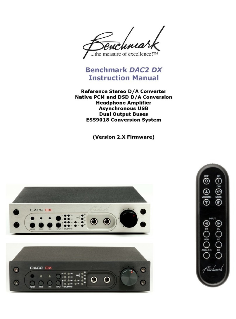
Benchmark DAC2 DX User manual
Benchmark
Benchmark DAC3 B User manual
Benchmark
Benchmark ADC16 User manual
Benchmark
Benchmark AD2402-96 User manual

Benchmark
Benchmark DAC3 HGC Quick start guide
Benchmark
Benchmark DAC1 USB User manual
Benchmark
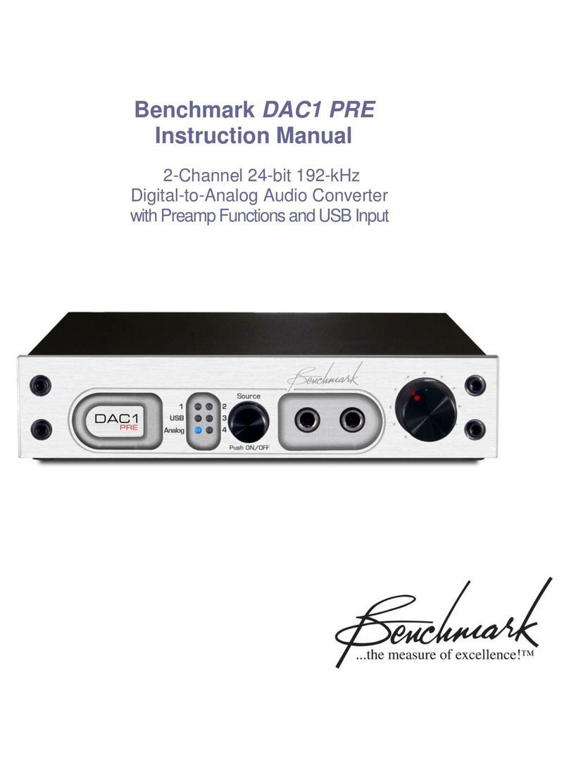
Benchmark DAC1 PRE User manual

