ADC1 USB Instruction Manual Page 3
Overview
The ADC1 USB is a reference-quality, 2-
channel, 192-kHz, 24-bit, analog-to-digital
converter featuring Benchmark's Advanced
USB Audio™ technology, phase-accurate
UltraLock™ clock system with multi-function
clock input and word clock output, and
Benchmark’s 9-segment dual-range digital
LED metering. The ADC1 USB is designed for
maximum transparency and is well suited for
the most demanding applications in studios
and mastering facilities. A rugged and
compact half-wide 1 RU enclosure also makes
the ADC1 USB an excellent choice for location
recording, broadcast facilities, and mobile
rigs. The internal power supply supports all
international voltages and has generous
margins for over and under voltage
conditions.
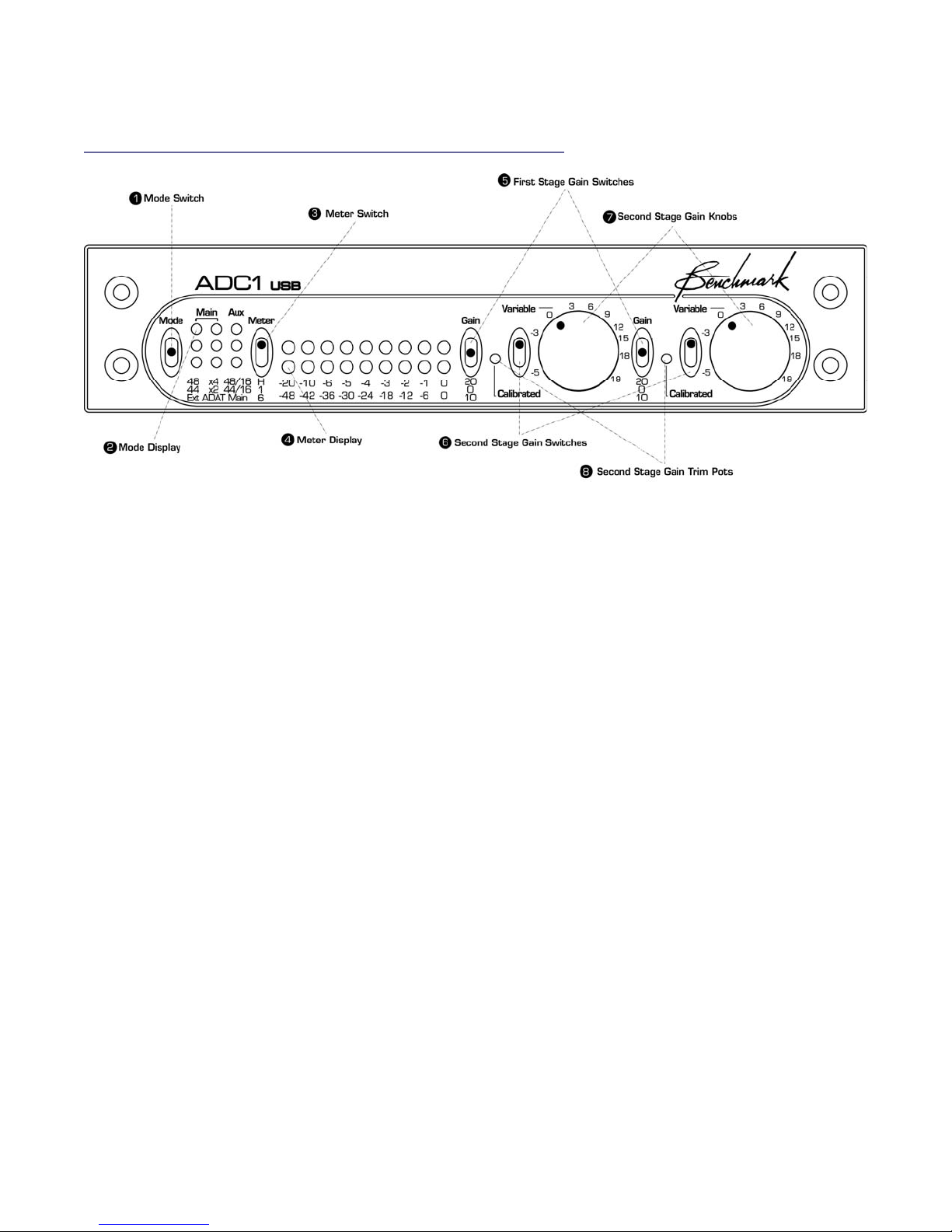
The ADC1 USB achieves outstanding
performance over a wide range of input
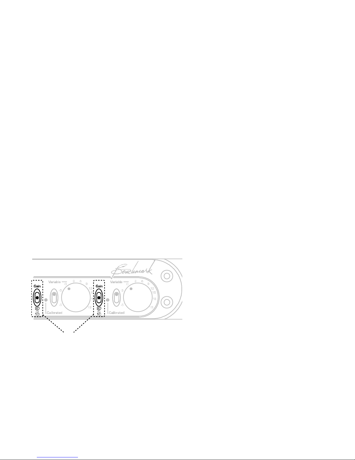
levels. Each channel has a 41-detent variable
gain control, a 10-turn calibration trimmer,
and a 3-position first-stage gain switch (0,
10, and 20 dB). Each channel has a two-
position toggle switch that selects either the
41-detent pot or the 10-turn trimmer. Both
the pot and the trimmer have a 20 dB
adjustment range. In combination with the
first-stage gain switch, these controls provide
exceptional SNR and THD+N performance
over a 40 dB adjustment range. The 10-turn
calibration trimmer may be used to calibrate
the ADC1 USB to precise studio reference
levels. It may also be used to optimize the
gain-staging between a microphone
preamplifier and the ADC1 USB.
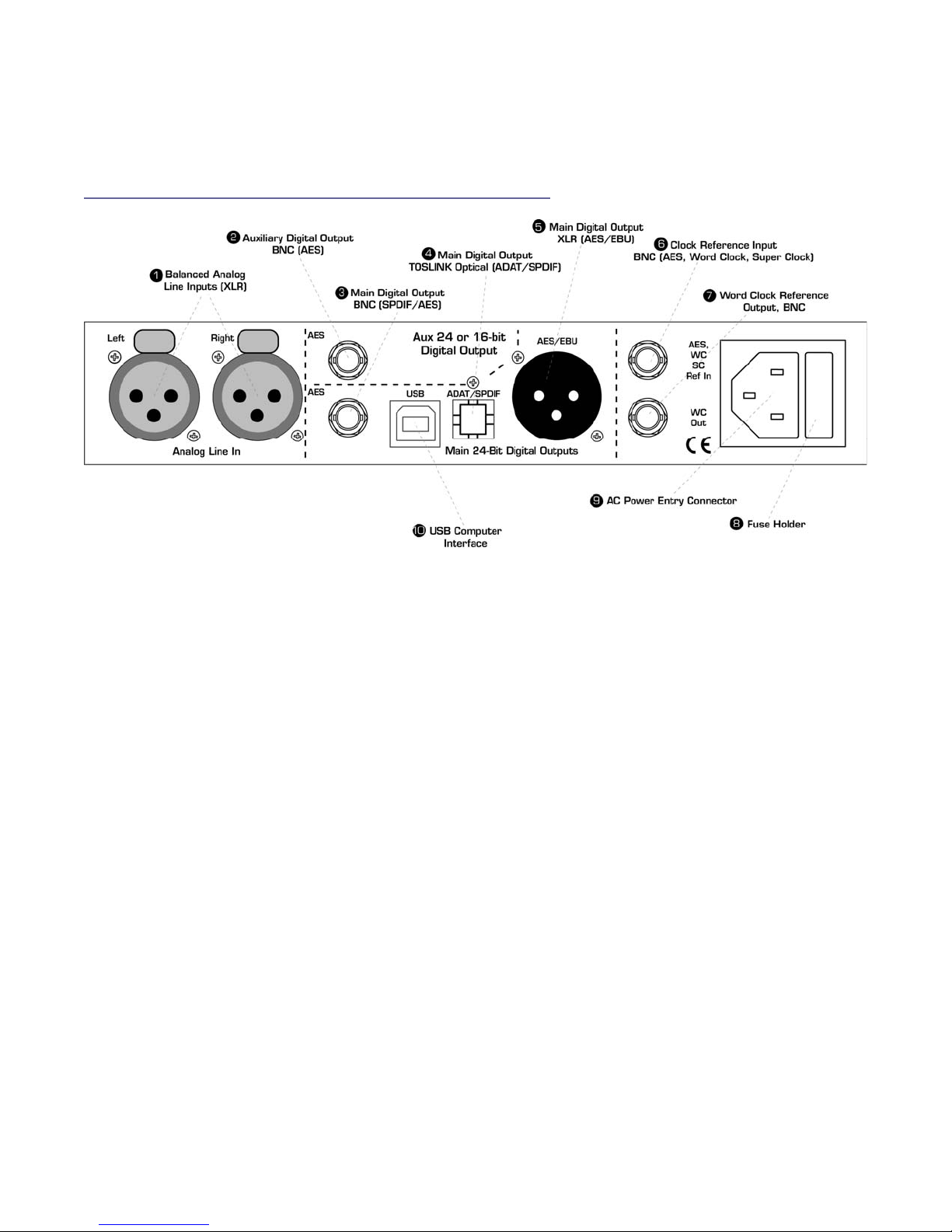
The ADC1 USB has a total of 5 digital outputs
(1 XLR, 2 coaxial, 1 optical and 1 USB) which
can operate simultaneously at up to three
independent sample rates. One of the five
outputs can be configured for 16-bit TPDF
dithered output. This unique flexibility allows
simultaneous recording to a CDR, a high-
resolution digital recorder, and a high
resolution DAW. For example the CDR may
operate at 44.1/16 while the DAW operates at
88.2/24 while the digital recorder operates at
192/24. The optical output supports AES or
ADAT formats at resolutions up to 192/24.
In ADAT mode, high sample rates are
supported using SMUX2 and SMUX4. Backup
and/or demo recordings can be created with
ease while high-resolution outputs are fed to
primary recording devices.
The ADC1 USB has a Word Clock output that
follows the sample rate of the Main Outputs
and Word Clock output is active in all modes
of operation.
A multi-format clock input automatically
recognizes AES/EBU, SPDIF, Word Clock, or
Super Clock signals. This clock input is used
to synchronize the Main Outputs. If desired,
the Main Outputs may be driven from internal
sources. The ADC1 USB will automatically
revert to an internal clock source when the
external clock is lost.
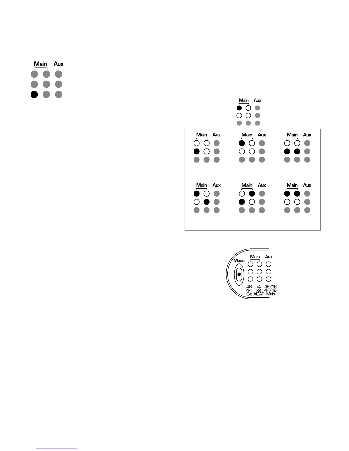
The ADC1 USB has two clock modes: Auto
and Internal. Both modes support 44.1, 48,
88.2, 96, 176.4 and 192 kHz.
The Auto mode allows the ADC1 USB to lock
to an external clock reference. In Auto mode,
the ADC1 USB will follow changes in sample
rate, and/or changes in the type of reference
signal (AES, SPDIF, word clock, or super
clock).
When a clock reference is not available, the
Internal mode must be used, and a sample-
rate must be selected (44.1, 48, 88.2, 96,
176.4, or 192 kHz). When the Internal mode
is active, the ADC1 USB is acting as clock
master, will only operate at the selected
sample rate, and will ignore any signal at the
clock reference input. If Internal mode is
used, all devices connected to the ADC1 USB
digital outputs will need to be configured to
lock to the ADC1 USB. Use the clock output
on the back of the ADC1 USB if the connected
devices require word clock.
The Benchmark UltraLock system is 100%
jitter immune. The A/D conversion clock is
totally isolated from the AES/EBU, SPDIF,
ADAT, WC, and super clock interfaces. This
topology outperforms two-stage PLL designs.