Benchmark DAC2 DX User manual
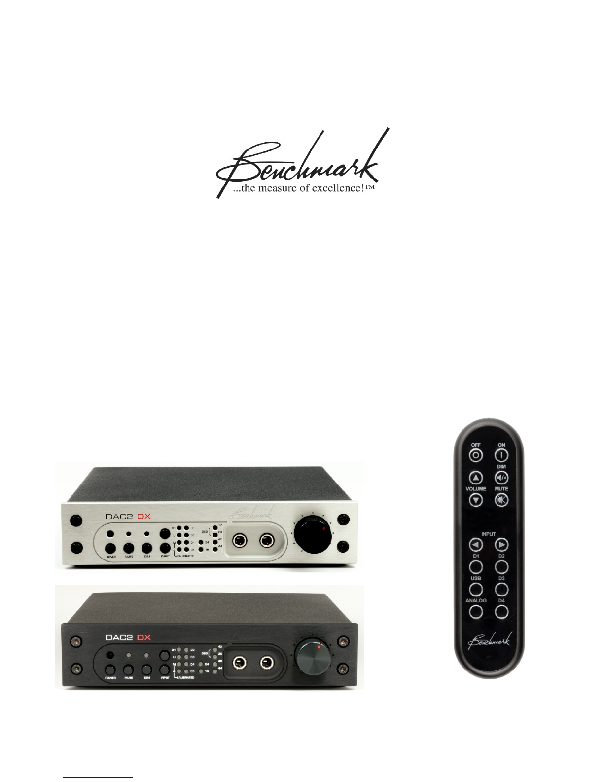
Benchmark DAC2 DX
Instruction Manual
Reference Stereo D/A Converter
Native PCM and DSD D/A Conversion
Headphone Amplifier
Asynchronous USB
Dual Output Buses
ESS9018 Conversion System
(Version 2.X Firmware)

Instruction Manual for DAC2 DX with 2.X Firmware - Rev. B Page 2
Safety Information
Fuses
CAUTION: FOR CONTINUED FIRE
HAZARD PROTECTION ALWAYS REPLACE
THE FUSES WITH THE CORRECT SIZE
AND TYPE (0.5A 250 V SLO-BLO® 5 X 20
MM –LITTELFUSE® HXP218.500 OR
EQUIVALENT). THE FUSE DRAWER
INCLUDES TWO FUSES. ALWAYS
REPLACE BOTH FUSES AT THE SAME
TIME.
AC Input Voltage Range
NOTE: THE DAC2 IS EQUIPPED WITH A
UNIVERSAL POWER SUPPLY. THERE IS
NO VOLTAGE SELECTION SWITCH. AC
VOLTAGE RANGE IS 88-264 VAC, 50-60
HZ. THE PRODUCT MAY ALSO BE
OPERATED FROM DC POWER OVER A
VOLTAGE RANGE OF 125-373 VDC.
Power Cord
CAUTION: ALWAYS USE A GROUNDED
POWER CORD. THE PRODUCT IS
EQUIPPED WITH A STANDARD IEC
POWER ENTRY MODULE. USE AN IEC
POWER CORD THAT IS EQUIPPED WITH
THE APPROPRIATE CONNECTOR FOR
YOUR LOCATION. CORDS ARE AVAILABLE
FROM YOUR DEALER.
Modifications
CAUTION: DO NOT SUBSTITUTE PARTS
OR MAKE ANY MODIFICATIONS
WITHOUT THE WRITTEN APPROVAL OF
BENCHMARK MEDIA SYSTEMS, INC.
MODIFICATION MAY CREATE SAFETY
HAZARDS AND VOID THE WARRANTY.
CAUTION: CHANGES OR MODIFICATIONS
NOT EXPRESSLY APPROVED BY
BENCHMARK MEDIA SYSTEMS COULD
VOID THE USER'S AUTHORITY TO
OPERATE THE EQUIPMENT UNDER FCC
REGULATIONS.
Repairs
CAUTION: DO NOT SERVICE OR REPAIR
THIS PRODUCT UNLESS PROPERLY
QUALIFIED. ONLY A QUALIFIED
TECHNICIAN SHOULD PERFORM
REPAIRS.

Instruction Manual for DAC2 DX with 2.X Firmware - Rev. B Page 3
Contents
Safety Information 2
Fuses 2
AC Input Voltage Range 2
Power Cord 2
Modifications 2
Repairs 2
Features 4
Introduction 5
Applications 5
DAC2 vs. DAC1 5
DAC2 Technologies 5
Front Panel 9
Rear Panel 9
Quick Start Guide 10
Audio Inputs 10
Remote Control 10
Front Panel Controls 11
Front Panel Displays 12
Headphone Jacks 15
Operational Details 16
DIM and MUTE Functions 16
AUTO-ON Function 16
Bi-directional 12V Trigger 17
CALIBRATED Mode 19
Preamp COMPATIBILITY Mode 20
USB MODE Selection 20
Driving Power Amplifiers 21
HPA2™ Headphone Amplifier 21
Digital Pass-Through 22
Firmware Version Identification 23
Rear Panel 24
Inputs 24
Outputs 27
AC Power-Entry and Fuse Module 28
Internal Settings 29
Jumper-Configured Options 29
Removing Top Cover 29
XLR Output Pads 29
Headphone Switch Configuration 30
Headphone Amplifier Gain 31
Digital PASS-THROUGH Function 32
Calibration Settings 33
Rack Mounting Options 35
Rack-Mount Version of the DAC2 DX 35
Connector Block 35
Premium ½-Wide Blank Rack Panel 36
Black ½-Wide Rack Panel 36
Universal Rack Adapter Tray 36
Rack Mounting Example 37
DAC1 and DAC2 Family History 38
DAC1 Series 38
DAC2 Series 38
Benchmark Technologies 40
Hybrid Gain Control™ 40
Native DSD Conversion 40
High-Headroom DSP 40
32-bit ESS SABRE D/A System 42
Diagnostic Displays 42
Bi-Directional 12 Volt Trigger 42
Distributed Power Regulation 42
HPA2™ Headphone Amplifier 42
Differential Amplifiers 43
Jitter-Immune UltraLock2™ 43
Multi-Mode Asynchronous USB Audio 46
USB Driver Installation 48
Performance Graphs 53
Specifications 69
Audio Performance 69
Group Delay (Latency) 70
Digital Audio Inputs 70
Jitter Tolerance 71
Balanced Analog Outputs 72
Unbalanced Analog Outputs 72
HPA2TM Headphone Outputs 73
Status Display 73
AC Power Requirements 74
Dimensions 74
Weight 74
Regulatory Compliance 75
FCC and RoHS Compliance Statements 75
FCC Notice (U.S. Only) 75
RoHS Compliance Information 75
CE Certificate of Conformity 76
Warranty Information 77
Benchmark 1-Year Warranty 77
Benchmark Extended Warranty Options 78
Notes on Warranty Repairs 78

Instruction Manual for DAC2 DX with 2.X Firmware - Rev. B Page 4
Features
HGC™(Hybrid Gain Control) –combines motor-driven active analog potentiometers, 32-bit
digital attenuators, and passive analog attenuators, to achieve state-of-the-art performance
ESS SABRE - 32-bit PCM D/A conversion system, four 32-bit D/A converters per channel
ESS SABRE –Native DSD D/A conversion system, four 1-bit DSD D/A converters per channel
Benchmark UltraLock2™ Jitter Attenuation System –eliminates jitter-induced distortion
High Headroom DSP - provides 4 dB of analog and digital headroom above 0 dBFS at an
output level of 24 dBu to completely eliminate the clipping of intersample peaks
Multi-Mode Asynchronous USB Audio 2.0 –24 bit/192 kHz, DSD (DoP 1.1)
Driverless Asynchronous USB Audio 1.1 –24-bit/96 kHz
Sample Rate Display –displays the measured sample rate, and format (PCM or DSD)
Word Length Display –displays the measured word length
HPA2™ reference-grade "0-Ohm" headphone power amplifier with dual high-current
outputs
HPA2™ gain jumpers for customizing headphone output gain for headphone sensitivities (Page
31)
2 Headphone Output Jacks –one jack automatically mutes the main outputs, mute feature
can be programmed to mute either output bus and may be disabled (Page 30)
1 AES XLR Digital Input –24-bit/192 kHz PCM, DSD (DoP 1.1)
2 Coaxial Digital Inputs –24-bit/192 kHz PCM, DSD (DoP 1.1)
2 Optical Digital Inputs –24-bit/96 kHz PCM
1 Coaxial Digital Output –digital pass through from USB, Coax, and optical inputs when
function is enabled (Page 32)
3 Stereo Analog Outputs –1 pair balanced (XLR) plus 2 pairs unbalanced (RCA)
2 Stereo Analog Output Buses –either or both buses can be set to fixed gain
Low-Impedance Passive Output Pads –0, 10, and 20 dB –optimize balanced output level
to power amplifiers and other downstream devices to maximize system SNR (Page 29)
IR Remote with metal housing provides control of all functions (optional on some models)
Volume-Control Bypass –places one or both analog output buses in a calibrated fixed-gain
mode (Page 19)
Mute –accessible from remote or front panel
Dim –Reduces output level by 20 dB, accessible from remote or front panel
Automatic De-Emphasis –automatically responds to consumer pre-emphasis bit (44.1, 48
kHz)
12V Trigger I/O –bi-directional 12V trigger can act as input, output, or both (Page 17)
AUTO-ON Function - can be programmed to turn on when AC is applied (Page 16)
Power Switch –very low standby power , <0.5 W at 120 VAC
High-Efficiency Low-Noise Power Supplies –only 12-15 W, 88-264 VAC, 50-60 Hz
Meets FCC Class B and CE emissions requirements
Tested for immunity to radiated and conducted RF interference

Instruction Manual for DAC2 DX with 2.X Firmware - Rev. B Page 5
Introduction
Applications
The DAC2 DX is a professional reference-
grade audio digital to analog converter with
Benchmark's HPA2™headphone amplifier.
The DAC2 DX supports 24-bit D/A conversion
of PCM at sample rates up to 192 kHz. It also
supports direct conversion of 1-bit DSD at a
2.8224 MHz sample rate. It is designed to be
very transparent and this makes it well-suited
for critical monitoring in studio control rooms
and mastering rooms.
The DAC2 DX is also well-suited for high-end
hi-fi environments. It includes a generous
collection of inputs and outputs and can serve
as the central component in any stereo hi-fi
system where all inputs are digital. The DAC2
DX provides D/A conversion, source selection,
volume control, and headphone amplification.
A remote control, 12V trigger, and volume
control bypass function provide the features
needed in a home environment.
The DAC2 DX is designed to directly drive a
wide variety of power amplifiers and powered
monitors. The balanced outputs include low-
impedance passive pads that can be adjusted
to optimize the gain staging between the
DAC2 DX and the power amplifier. This gain
optimization can provide very substantial
improvements in the system-level SNR and
THD+N performance.
DAC2 vs. DAC1
The DAC2 adds these features that are not
found on the DAC1:
Asynchronous 192kHz USB Audio 2.0
32-bit D/A conversion system
Word Length Display
Sample Rate Display
Polarity Control
Direct DSD D/A Conversion
-20 dB DIM
Bi-Directional 12V Trigger
Power Switch with Auto-On Function
Volume Control Bypass
Digital Pass-Through
High-Headroom DSP
Dual-Domain Hybrid Gain Control
Additional I/O
DAC2 Technologies
Parallel Conversion Structure
The conversion system in the DAC2 DX
achieves a 4.8 dB signal to noise
improvement through the use of 3:1
summing on the main outputs. The ES9018
D/A is an 8-channel 32-bit converter. In the
DAC2 DX, three channels are summed in the
analog domain to form the main outputs. The
remaining two channels provide the auxiliary
outputs.
The 3:1 summing also improves the THD. The
non-linearities in individual conversion
channels are averaged across the four
summed channels and incoherent non-
linearities are attenuated by almost 4.8 dB.
High-Headroom Digital and Analog
Processing
The DAC2 DX has generous amounts of
analog and digital headroom. The analog clip
point is above 29 dBu. The digital clip point is
28 dBu. When operating at a typical -20 dB at
+4 dBu studio calibration, the DAC2 DX has
4 dB of digital headroom above 0 dBFS. This
digital headroom prevents the clipping of
intersample overs.
No Clipping of Intersample Overs
The DAC2 is one of very few D/A converters
that can accurately reproduce intersample
overs without clipping. Intersample peaks can
reach +3.01 dBFS and commonly occur many
times per second in most 44.1 kHz and 48
kHz recordings. When recordings are ripped
using lossy compression systems (such as
MP3), additional intersample overs are often
created. Most converters (including the
DAC1) produce bursts of distortion at every
occurrence of an intersample over. In
contrast, the DAC2 and DAC3 converters
cleanly reproduce all intersample overs.

Instruction Manual for DAC2 DX with 2.X Firmware - Rev. B Page 6
Low-Noise Power Supplies
The DAC2 DX uses high-efficiency low-noise
power supplies. Each critical subsystem also
has at least one dedicated low-noise
regulator. The high-efficiency supplies deliver
the substantial power required by the low-
impedance circuits, the headphone amplifier,
and the output line drivers. A power switch is
included. The standby power consumption is
less than 0.5 W when the unit is off.
Low Magnetic Emissions
The magnetic components in the DAC2 DX
power supplies operate at over 800 kHz. This
allows the use of very small magnetic
components that emit correspondingly small
magnetic fields. This virtually eliminates all
traces of line-frequency components in the
output spectrum of the DAC2 DX. This also
means that the DAC2 DX can be placed in
close proximity to any audio component
without causing interference with the other
component.
UltraLock2™Clock System
UltraLock2™provides the outstanding jitter
attenuation of Benchmark's UltraLock™
system while providing an improved SNR.
Dual-Mode USB Input
The DAC2 DX has a USB input that can be
operated in two modes; driverless USB
Audio 1.1, and a high sample rate USB
Audio 2.0. Both use asynchronous clocking
to eliminate the USB interface as a source of
clock jitter.
Note: To provide full backward and forward
compatibility, the DAC2 DX uses the DAC2
USB drivers. This prevents the need to install
two different sets of drivers. Please note that
the DAC2 DX USB input will be identified as
"Benchmark DAC2" in your computer control
panels. This is intentional.
Asynchronous USB Audio 2.0
The USB Audio 2.0 interface supports DSD
and 192 kHz, 24-bit PCM. No drivers are
required for Apple operating systems. Drivers
are provided for older Windows operating
systems at: BenchmarkMedia.com/drivers
Native Asynchronous USB 1.1
The DAC2 DX has a driverless USB Audio 1.1
mode that supports 96 kHz, 24-bit PCM with
all operating systems. This mode provides a
quick and easy connection to a wide variety of
computers and tablets without installing a
driver.
32-bit Digital Gain Control
The DAC2 DX uses the digital section of
Benchmark's dual-domain HGC™ system
(used in the DAC2 HGC).
Benchmark’s unique motor-driven volume
control sets the gain of a 32-bit dithered
digital gain control. The 32-bit digital output
feeds the 32-bit D/A conversion system.
The 32-bit digital gain control delivers low
distortion, accuracy, and precise left-right
gain matching. The noise-free 32-bit dithered
system preserves musical details over a very
wide range of output levels.
The XLR outputs leverage the low-impedance
passive analog attenuation system. When
properly configured, the entire dynamic range
of the DAC2 DX can be lined up with the
dynamic range of the power amplifier. This
matching can provide a dramatic
improvement in the system-level signal to
noise ratio.
The volume control is a servo-driven analog
potentiometer. This control rotates in
response to commands from the remote
control while providing the convenience of
manual adjustments with a physical knob.
The potentiometer produces a DC voltage that
controls the gain of a dithered 32-bit

Instruction Manual for DAC2 DX with 2.X Firmware - Rev. B Page 7
multiplier. The outputs of the multiplier drive
the 32-bit D/A converters.
Low-Impedance Passive Attenuators
Like the DAC1 and DAC2 includes low-
impedance passive attenuators on the XLR
outputs (Page 29).
These attenuators can be adjusted in 10 dB
steps to optimize the interface with the power
amplifier or powered monitors. This
optimization places the volume control in its
best operating range. This exclusive
Benchmark feature can provide substantial
improvements in the overall performance of
the playback signal chain.
Native DSD Conversion
The DAC2 DX supports native DSD
conversion. This feature was not available on
the DAC1. DSD signals can be delivered to
the USB or Coaxial inputs in DoP 1.1 format.
The DSD signal is then routed directly to a
bank of 1-bit DSD D/A converters. Three
balanced 1-bit converters are summed
together for each of the MAIN outputs.
Digital Pass-Through
The second coaxial input (D5) can be
reconfigured as a digital output (Page 32).
When D5 is configured as an output, any
selected digital input is passed through to D5
without any processing. Optical, XLR, coaxial,
and USB inputs can be passed through to the
D5 connector. PCM and DoP formatted DSD
can both be passed through the D5 connector
while also being sent to the D/A converter.
The pass-through function even works with
special signals such as DTS, Dolby Digital,
even though these signals cannot be decoded
by the DAC2 DX.
Volume Control Bypass
The CALIBRATED mode can be activated for
either or both output buses (Page 19).
The factory default calibration at 0 dBFS is
+24 dBu on the XLR outputs (pads at 0 dB)
and 2 Vrms on the RCA outputs. If your
studio calibration is different, the calibration
can be adjusted in 1 dB increments from +20
dBu to +28 dBu using the removable jumpers
on connector P6 (Page 33).
The Mand/or Alights will be on when the
MAIN and/or AUXILIARY outputs are in the
CALIBRATED mode. A slow flashing light
indicates that a calibrated output is muted.
The DIM function is disabled on any output
group that is operating in CALIBRATED
mode.
When the CALIBRATED mode is off, the M
and/or Alights will flash rapidly when the
volume of the MAIN and/or AUXILIARY
outputs are being adjusted.

Instruction Manual for DAC2 DX with 2.X Firmware - Rev. B Page 8
The CALIBRATED mode is similar to the
CALIBRATED switch setting on the DAC1
except that the DAC2 DX system is much
more flexible. The DAC2 DX has two
independent output buses that can be
programmed differently. In addition the
settings for these buses are individually
programmable for each digital input on the
DAC2 DX. This flexibility has many
applications in studio and home
environments.
Relay-Muted Analog Outputs
The XLR and RCA analog outputs are
equipped with mute relays that keep the
outputs muted while powering on or off.
These relays eliminate pops and clicks at the
unit power up or down.
Bi-directional 12V Trigger
The 12 Volt trigger can be connected to other
audio components so that an entire audio
system can turn on and off in a sequenced
fashion (Page 17).
The DAC2 DX trigger I/O can be connected
to a preamplifier, power amplifier, or both.
The DAC2 DX will pull the trigger I/O to 12
volts DC while the DAC2 DX is on. If the
DAC2 DX is off and an external device pulls
the trigger I/O to 12 volts, the DAC2 DX will
turn on.
Auto-On Function
The DAC2 DX can be programmed to
automatically turn on when AC power is
applied (Page 16).
Preamp COMPATIBILITY Mode
This feature was added in Version 2.0. If you
have an older version, an update is available.
The COMPATIBILITY mode disables the
volume control when the DAC2 feeds a
preamplifier that will be used to control the
system playback volume. When this mode is
used with a Benchmark preamplifier or line
amplifier, such as the HPA4, a single
Benchmark IR remote can be used to control
both devices (Page 20).

Instruction Manual for DAC2 DX with 2.X Firmware - Rev. B Page 9
Front Panel
Rear Panel

Instruction Manual for DAC2 DX with 2.X Firmware - Rev. B Page 10
Quick Start Guide
Audio Inputs
The DAC2 DX features six stereo digital
inputs (1 AES XLR, 2 coaxial, 2 optical, and 1
USB). The XLR, coaxial and optical inputs
accept professional (AES), consumer (S/PDIF)
and DoP DSD data formats.
Tip: We recommend using the coaxial or USB
inputs for DSD and for PCM sample rates
above 96 kHz. Optical interfaces are rated for
96 kHz data rates and may not be reliable for
DSD or sample rates above 96 kHz.
Remote Control
The remote control is designed to have a long
operating range. In most applications it is not
necessary to point the remote directly at the
DAC2 DX.
The chart at the right summarizes the
functions of the IR remote control.
OFF
Turns the unit off. Any devices
slaved to the 12V TRIGGER will
also turn off in a controlled
sequence.
Press and hold the OFF button for
3 seconds to force the 12V
TRIGGER off (only necessary
when another device is acting as a
TRIGGER BUS MASTER).
ON
Turns the unit on. Any devices
slaved to the 12V TRIGGER will
also turn on in a controlled
sequence.
VOLUME
Turns the volume up or down.
MUTE
Toggles the MUTE function.
Press and hold the MUTE button
for 10 seconds to toggle the
CALIBRATED mode on the MAIN
outputs.
DIM
Toggles the -20 dB DIM function.
Press and hold the DIM button for
10 seconds to toggle the
CALIBRATED mode on the AUX
outputs.
INPUT
Selects the inputs.
D1
Selects optical digital input D1.
D2
Selects optical digital input D2.
D3
Selects XLR digital input D3.
D4
Selects coaxial digital input D4
then toggles between D4 and D5.
USB
Selects USB input.
Press and hold the USB button for
3 seconds to toggle between the
USB 1.1 and USB 2.0 modes.
Analog
Selects analog input A1 and then
toggles between A1 and A2.
Instruction Manual for DAC2 DX with 2.X Firmware - Rev. B Page 11
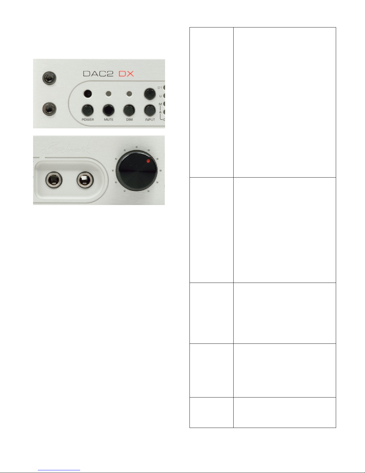
Front Panel Controls
The front panel controls duplicate all of the
functions that are available from the remote
control.
Two additional functions, AUTO-ON, and
COMPATIBILITY mode are only controllable
from the front panel.
The AUTO-ON function keeps the
DAC2 on whenever AC line voltage is
supplied.
The COMPATIBILITY mode disables
the volume control when the DAC2
feeds a preamplifier that will be used
to control the system playback
volume. mote can be used to control
both devices.
Tip: When AUTO-ON is enabled, a switched
AC outlet can be used to turn your system on
and off. The 12V TRIGGER I/O can be used
as a trigger output to control the power state
of additional components.
The chart at the right summarizes the
functions of the front-panel controls.
POWER
Turns the unit on or off. Any
devices slaved to the 12V
TRIGGER will also turn on or
off in a controlled sequence.
Starting with the unit off, press
and hold the POWER button
for 10 seconds to set the
AUTO-ON function.
Starting with the unit on, press
and hold the POWER button
for 10 seconds to clear the
AUTO-ON function.
If AUTO-ON is set, the
POWER button will toggle
MUTE on and off (the unit will
remain on).
MUTE
Press once to toggle the -20 dB
DIM function.
Press and hold the MUTE
button for 10 seconds to toggle
the CALIBRATED mode on the
MAIN outputs.
Simultaneously hold the MUTE
and INPUT-UP keys for 10
seconds to activate or
deactivate the
COMPATIBILITY mode.
DIM
Press once to toggle the -20 dB
DIM function.
Press and hold the DIM button
for 10 seconds to toggle the
CALIBRATED mode on the
AUX outputs.
INPUT
Selects the inputs.
Select USB and press lower
button for 10 seconds to toggle
between the USB 1.1 and USB
2.0 modes.
VOLUME
(knob)
Sets the volume of all outputs
that are not in CALIBRATED
mode.
Instruction Manual for DAC2 DX with 2.X Firmware - Rev. B Page 12
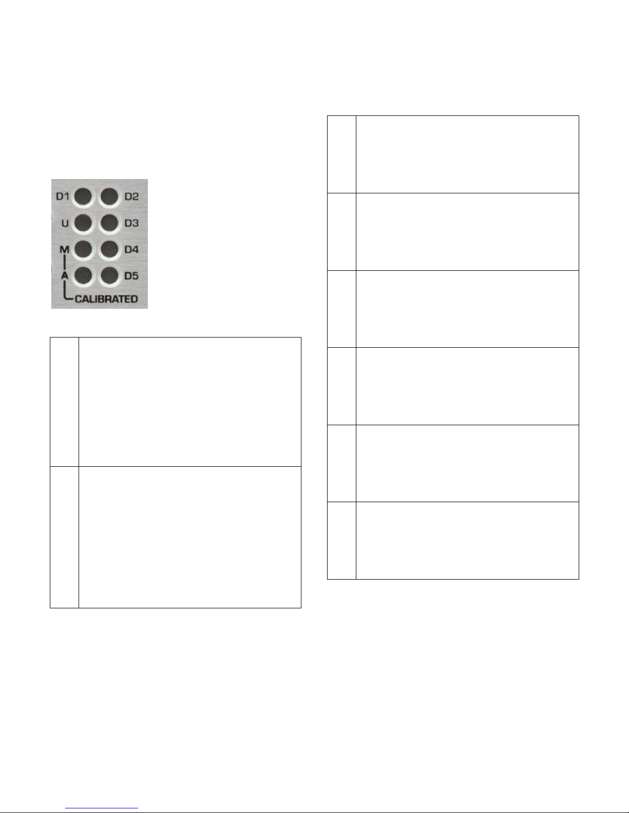
Front Panel Displays
There are sixteen status indicator lights on
the front panel. At least one light will be
illuminated whenever power is on.
Calibration and Input Indicators
The Mand Aindicators
show that the
CALIBRATED mode is
active for the MAIN
and/or AUX outputs.
The input indicators (U
and D1-D5) show which
input is selected.
A
This light will flash rapidly when the
volume of the AUX bus is being
adjusted.
A solid light indicates that the AUX bus
is in CALIBRATED mode.
A slow-blinking light indicates that the
AUX bus is in CALIBRATED mode but
the output is muted or dimmed.
M
This light will flash rapidly when the
volume of the MAIN bus is being
adjusted.
A solid light indicates that the MAIN
bus is in CALIBRATED mode or in
COMPATIBILITY mode.
A slow-blinking light indicates that the
MAIN bus is in CALIBRATED mode but
the output is muted.
U
A solid light indicates that the USB input
is selected and operating normally.
A blinking light indicates that the input
is selected but a connection to a
computer has not been established.
D1
A solid light indicates that optical input
D1 is selected and operating normally.
A blinking light indicates that the input
is selected but audio data is not being
received.
D2
A solid light indicates that optical input
D2 is selected and operating normally.
A blinking light indicates that the input
is selected but audio data is not being
received.
D3
A solid light indicates that XLR input D3
is selected and operating normally.
A blinking light indicates that the input
is selected but audio data is not being
received.
D4
A solid light indicates that coaxial input
D4 is selected and operating normally.
A blinking light indicates that the input
is selected but audio data is not being
received.
D5
A solid light indicates that coaxial input
D5 is selected and operating normally.
A blinking light indicates that the input
is selected but audio data is not being
received.
Note: D5 cannot be selected if the Digital
Pass Through function is enabled.
Instructions for configuring this jumper-
selected function can be found in the
Internal Settings section of this manual
(Page 29).

Instruction Manual for DAC2 DX with 2.X Firmware - Rev. B Page 13
Input Error Codes
An input indicator (Uor D1-D5) flash when
an error is present on the selected digital
input. Use the following table to diagnose the
problem:
Slow Flash
(2Hz)
No digital signal (output
muted)
Med. Flash
(7Hz)
Data transmission errors or
Non-PCM (output muted)
Rapid flashes
(14Hz)
Non-audio data is being
received (output muted)
Intermittent
flashes
Some data corruption is
occurring, converter may be
interpolating to replace
invalid samples, check the
cable.
Tip: Common causes of input errors:
Disconnected or faulty cable
Use of excessively long digital cables
Use of analog cables for digital signals
Use of optical cables for sample rates
exceeding 96 kHz
Incompatible data type (AC3, ADAT, etc.)
Non-audio data is being received
MUTE and DIM Indicators
MUTE
Indicates that all outputs are
muted.
DIM
Indicates that all non-calibrated
outputs are dimmed by 20 dB.
Digital Format Indicators
Two lights indicate
the measured word
length of the
selected digital
input.
Four lights indicate
the measured
sample rate and
format of the
selected digital
input.
Tip: Computers, disk players and streaming
devices often subject the digital signal to
sample rate conversion, changes in word
length, PCM to DSD conversions, and other
forms of digital processing that may degrade
the quality of the audio. This display makes it
easy to detect these processes.
Word Length Indicators
The 16 and 24 lights indicate the measured
word length of the selected digital input. The
DAC2 DX detects active data bits and
displays the results as follows:
16 Only
Measured input word length is
16 bits.
16 and 24
Measured input word length is
17 to 23 bits.
24 Only
Measured input word length is
24 bits.
Both Off
Measured input word length is
less than 16 bits.
Tip: The DIM button will not change the level
of outputs that are in the CALIBRATED
mode.

Instruction Manual for DAC2 DX with 2.X Firmware - Rev. B Page 14
Format indicators
The 44, 48, 2X, 4X and DSD lights indicate
the sample rate and format of the selected
digital input as follows:
44 Only
The input format is PCM at a
sample rate of 44.1 kHz (CD
sample rate).
48 Only
The input format is PCM at a
sample rate of 48 kHz (often
used with video).
44 and 2X
The input format is PCM at a
sample rate of 88.2 kHz
(high-resolution audio
format).
48 and 2X
The input format is PCM at a
sample rate of 96 kHz (high-
resolution audio format).
44 and 4X
The input format is PCM at a
sample rate of 176.4 kHz
(high-resolution audio
format).
48 and 4X
The input format is PCM at a
sample rate of 192 kHz
(high-resolution audio
format).
DSD
(4x and 2X)
The input format is 1-bit DSD
at a sample rate of 2.8224
MHz (high-resolution audio
format). Note: DSD must be
streamed in DoP format.
All Off
Digital signal is not present
or is not in a supported
format.

Instruction Manual for DAC2 DX with 2.X Firmware - Rev. B Page 15
Headphone Jacks
By default, the left-
hand jack mutes the
MAIN outputs.
By default, the right-
hand jack keeps all
outputs active.
Headphone Mute Switches
Both headphone jacks includes include
switches that can be programmed to mute
the MAIN outputs. When enabled, the MAIN
analog outputs (XLR and RCA) are muted
when a headphone plug is inserted. This
feature allows the listener to switch from
loudspeaker to headphone playback
seamlessly. This Auto-Mute feature can be
disabled or enabled on one or both jacks
using internal jumpers.
Note: Instructions for setting the Auto-Mute
jumpers can be found in the Internal
Settings section of this manual (Page 29).
Tip:Use the left-hand jack to mute your
loudspeaker system. Use the right-hand jack
to keep all outputs active.
Driving Two Sets of Headphones
The HPA2™ is specifically designed with
enough power to drive two sets of
headphones.
Tip: The Volume Control simultaneously
adjusts the level for both jacks. If two
listeners will be simultaneously using the
headphone outputs, we recommend using
headphones with identical or similar voltage
sensitivities.
HPA2TM Headphone Power Amplifier
The headphone jacks are driven by
Benchmark's HPA2™headphone power
amplifier. This very clean power amplifier can
deliver the current and voltage required by
some of the most demanding headphones.
The output impedance of the HPA2™is very
close to 0 Ohms. This low output impedance
delivers a high damping factor so that the
amplifier can maintain precise control over
the headphone transducers.
Headphone voltage sensitivities vary
substantially, so we have equipped the
HPA2™ with Gain-Range jumpers that can
be used to customize the headphone amplifier
to your favorite headphones. If you find that
you have too much output (volume control
set below 11 o'clock), there are internal
jumpers that can be adjusted to decrease the
output level by 10 dB or 20 dB relative to the
factory default setting.
Note: Instructions for setting the headphone
Gain-Range jumpers can be found in the
Internal Settings section of this manual
(Page 29).
Tip:For optimal performance, the headphone
Gain-Range jumpers should be set so that
comfortable listening levels occur when the
volume control is set above the 11 o'clock
position.

Instruction Manual for DAC2 DX with 2.X Firmware - Rev. B Page 16
Operational Details
DIM and MUTE Functions
Definition: If the DIM and MUTE and
COMPATIBILITY modes are all off, the
DAC2 DX is in NORMAL mode.
DIM Function
The DIM function reduces the output level by
20 dB. To toggle between NORMAL and DIM
volume, press the DIM button on the remote
or the DIM button on the front panel.
The DIM light will turn on whenever DIM is
active.
The DIM function makes it convenient to fade
back and forth between normal and
background playback volume levels.
If the volume is adjusted while DIM is active,
the NORMAL volume setting will change by
the same amount.
If an output bus is set to CALIBRATED
mode, DIM is disabled on that bus.
TIP: In the studio, the DIM function allows a
temporary reduction in level without losing
the volume setting that was being used for
monitoring.
Tip: In home applications the DIM function
allows temporary reductions in volume during
TV commercial breaks, phone calls, or other
interruptions, without losing the volume
setting that was being used for normal
listening.
MUTE Function
The MUTE function immediately mutes all
outputs. To toggle this function, press the
MUTE button on the remote or press the
MUTE button on the front panel.
The MUTE light will turn on whenever MUTE
is active.
Tip: If the unit is in MUTE, press the DIM
key to immediately enter the DIM mode.
Tip: If the unit is in MUTE and/or DIM press
the ON key (on the remote) to enter the
NORMAL mode.
Tip: if the unit is in DIM, press the MUTE
key to toggle between DIM and MUTE.
AUTO-ON Function
The DAC2 DX can be programmed to
automatically turn on whenever AC power is
applied. This function allows automation using
switched AC outlets. When AUTO-ON is
enabled, the DAC2 DX cannot be turned off
without removing AC power.
The AUTO-ON function is programmed by
pressing and holding the POWER button on
the front panel for 10 seconds. It is the only
function that cannot be programmed from the
remote control. This limitation prevents
accidental access to this special feature.
Enabling AUTO-ON
Starting with the DAC2 DX off, press and
hold the POWER button for 10 seconds.
If AUTO-ON has been successfully enabled,
the POWER button will now function as a
MUTE button. The OFF button on the remote
will also function as a MUTE button when
AUTO-ON is enabled.
Disabling AUTO-ON
Starting with the DAC2 DX on, press and
hold the POWER button for 10 seconds. At
the end of 10 seconds the DAC2 DX will
power down if the AUTO-ON mode has been
successfully disabled.

Instruction Manual for DAC2 DX with 2.X Firmware - Rev. B Page 17
Bi-directional 12V Trigger
Benchmark has reinvented the 12 volt trigger
by adding bi-directional signaling. The trigger
connection on the DAC2 DX can be used as
an input, an output, or both. It is compatible
with any common 12 volt trigger input or
output. The 12V TRIGGER I/O can be used
to turn other audio components on when the
DAC2 DX turns on. The DAC2 DX can also
turn on and off in response to other
connected components. The Benchmark bi-
directional 12V Trigger is compatible with
virtually all trigger systems.
The 12V TRIGGER I/O can be connected to
the trigger input or output ports on a
preamplifier, power amplifier, or both.
The DAC2 DX can send a 12 Volt DC trigger
signal to start other components in the
system, or it can wake up in response to an
externally generated trigger signal. The DAC2
DX automatically configures its trigger I/O
port as an input (slave) or output (master).
Trigger Output (DAC2 DX is Master)
When the DAC2 DX is turned on using the
POWER button (on the front panel), or the
ON button (on the remote), the DAC2 DX
configures itself as a trigger master and will
drive the 12V TRIGGER I/O to 12 volts DC
and hold it there while the DAC2 DX is on.
The trigger output signal generated by the
DAC2 DX is delayed so that the DAC2 DX
can stabilize before downstream devices
(such as power amplifiers) turn on. When
powering down, the DAC2 DX will mute
before allowing the trigger line to drop low.
The DAC2 DX keeps the internal power
supplies running for 10 seconds after
dropping the trigger. This delay gives other
triggered components ample time to mute
and shut down.
If the AUTO-ON function is enabled, the
DAC2 DX will automatically turn on when AC
power is applied, configure itself as a trigger
master, and ignore any external signaling on
the 12V TRIGGER I/O line. In AUTO-ON
mode, the DAC2 DX will always drive the
12V TRIGGER I/O line to 12 V (after a short
start-up delay).
Trigger Input - (DAC2 DX is Slave)
If the DAC2 DX is off and an external device
pulls the trigger I/O to 12 volts, the DAC2
DX will configure itself as a trigger slave and
will follow the actions of the trigger input. The
DAC2 DX will then turn off when the external
device stops sending the 12 V trigger.
Typical Trigger Applications
In most systems, the 12V TRIGGER will be
used to connect the DAC2 DX to one other
device. The DAC2 DX can be connected to
the first trigger input at the beginning of a
trigger chain, or it can be connected to the
last trigger output at the end of the chain
(less common).
Typical trigger applications:
DAC2 DX →Amplifier
DAC2 DX →Amplifier →Amplifier
DAC2 DX →Preamplifier →Amplifier
Trigger Bus Applications
The Benchmark bi-directional trigger system
also supports multiple trigger ports wired
together on a bus.
A group of Benchmark trigger ports can be
connected to a group of non-Benchmark
trigger input ports to form a single trigger
bus. A bus should never be connected to
more than one non-Benchmark trigger output
port. If an output port is connected to the
bus, this device should be used to start the
audio system.
A 3.5 mm (1/8") TRS "Y" cable can be used to
split the trigger output of the DAC2 DX to
feed more than one trigger input.
Benchmark AHB2 power amplifiers have two
trigger I/O ports that are wired in parallel.
This makes it easy to connect more than one
power amplifier to a trigger bus (without the

Instruction Manual for DAC2 DX with 2.X Firmware - Rev. B Page 18
use of a "Y" cord). Connect a trigger cable
between the DAC2 DX and the first amplifier.
Use another trigger cable to connect this
amplifier to the next amplifier. Any number of
Benchmark amplifiers can be added to the
trigger bus. The DAC2 DX will turn on first,
and after a delay, all of the amplifiers will
turn on together.
Bi-Directional Trigger Applications
Benchmark products support bi-directional
communications over a trigger bus. Any
Benchmark product connected to the bus can
turn the entire system on or off. Because of
the bi-directional design, any power button on
a Benchmark DAC2 DX or AHB2 can be used
to start or stop the system.
The Benchmark device that starts the system
will become the trigger master. If the trigger
master is turned off, all slave devices will
follow. If a slave device is turned off, all other
devices will stay on.
If the DAC2 DX is used to turn the system
on, any connected AHB2 amplifiers will
become slave devices and they can be turned
off without shutting down the DAC2 DX. This
feature makes it easy to turn the AHB2
amplifier(s) off when listening to headphones.
Slave devices can force the entire trigger bus
to shut down if the POWER button or OFF
button is pressed and held for 3 seconds.
Tip: Press and hold the POWER button on
any Benchmark device for 3 seconds to force
a shutdown of the entire trigger-connected
system.
Trigger Specifications
The Benchmark 12V TRIGGER I/O has a
wide operating range to allow interfacing with
most other DC trigger systems. It should only
be used with trigger inputs that are designed
to tolerate 12 VDC.
12 VDC 200 mA current-limited output
Input responds to 3.3 V logic and
higher
Maximum input voltage = 30 VDC
Maximum reverse input voltage = -0.3
VDC
Input Impedance = 20 k Ohms
1/8" (3.5 mm) TRS jack
Tip = 12 Volt Trigger I/O
Ring = no connection
Sleeve = chassis ground

Instruction Manual for DAC2 DX with 2.X Firmware - Rev. B Page 19
CALIBRATED Mode
The CALIBRATED mode sets the MAIN
and/or AUX output buses to calibrated levels.
The two output buses are individually
programmable for each digital input.
The factory preset calibration is +24 dBu at 0
dBFS on the XLR outputs, and 2 Vrms at 0
dBFS on the RCA outputs. The calibration is
adjustable up or down by up to 4 dB in 1 dB
steps using internal jumpers. On the XLR
outputs the calibration range is +20 dBu to
+28 dBu. On the RCA outputs the calibration
range is 1.26 to 3.17 Vrms.
The CALIBRATED mode is similar to the
CALIBRATED switch setting on the DAC1
except that the CALIBRATED mode can be
programmable separately for each input.
The CALIBRATED mode has two distinct
applications:
Volume Control Bypass - useful
when the system has an upstream
digital volume control or a downstream
analog volume control
Calibrated Output - useful in studio
applications where calibrated levels
are needed
The Mlight indicates that the MAIN bus is in
CALIBRATED mode.
The Alight indicates that the AUX bus is in
CALIBRATED mode.
Enabling the CALIBRATED Mode
1. Select the input channel that you wish
to program
2. Press and hold the MUTE button for
10 seconds to toggle CALIBRATED
mode on the MAIN outputs
3. Press and hold the DIM button for 10
seconds to toggle CALIBRATED mode
on the AUX outputs.
CALIBRATED Mode - Volume Control
Bypass
The CALIBRATED mode is useful whenever
the system volume will be controlled before
or after the DAC2 DX. It is usually best to
avoid having two cascaded volume controls in
a playback system. Dual controls will usually
degrade the noise performance of the system
and they can lead to confusion.
If the DAC2 DX feeds a preamplifier, the
preamplifier will provide a downstream analog
volume control for the system and the DAC2
DX should be placed in CALIBRATED mode
for all inputs.
If the DAC2 DX is directly feeding an
amplifier, but one or more sources have
volume controls, the sources with volume
controls can be set to CALIBRATED mode.
Example 1: The USB input is fed from a
computer that has an internal digital volume
control. If you wish to use the volume control
in the computer exclusively, you will want to
enable the CALIBRATED mode on the USB
input. If you do not wish to use the computer
volume control, leave the CALIBRATED
mode off and disable the computer volume
control (or set it to maximum).
Example 2: Digital input D3 is fed from a
digital audio workstation and the workstation
will be controlling the playback level in the
control room. The volume control on the
DAC2 DX will be controlling the playback
level in another room. The MAIN outputs will
be driving the control room monitors and the
AUX outputs will be driving the monitors in
the other room. Select D3 and enable the
CALIBRATED mode on the MAIN outputs
only.
Example 3: Input D4 is being driven by a
music server. A power amplifier in the same
room is driven from the MAIN outputs.
Another room needs a fixed line-level feed to
an integrated amplifier (with volume control).
Select D4 and enable the CALIBRATED
mode on the AUX output only.

Instruction Manual for DAC2 DX with 2.X Firmware - Rev. B Page 20
Preamp COMPATIBILITY Mode
The COMPATIBILITY mode sets the MAIN
output bus to its calibrated output level and
disables the motorized volume control. The
main outputs can then feed a preamplifier
that will be used to control the system
playback volume. When this mode is used
with a Benchmark preamplifier or line
amplifier, such as the HPA4, a single
Benchmark IR remote can be used to control
both devices.
In COMPATIBILITY mode:
M_CAL mode is on for all inputs.
MUTE is disabled.
DIM is disabled.
Remote INPUT select arrows are
disabled.
Remote VOLUME commands are
disabled.
Enabling the COMPATIBILITY mode:
Simultaneously hold the MUTE and
INPUT-UP keys for 10 seconds to
activate or deactivate this feature.
The Mlight will be illuminated on all
inputs when COMPATIBILITY mode
is enabled.
The DIM and MUTE keys will be
disabled when COMPATIBILITY
mode is enabled.
The DAC2 will not respond to the
DIM, MUTE, VOLUME-UP, VOLUME-
DOWN, INPUT-UP, or INPUT-
DOWN keys on the IR remote when
COMPATIBILITY mode is enabled.
USB MODE Selection
The DAC2 DX supports two USB MODES:
USB Audio 1.1 mode - up to 24 bits
at 96 kHz
USB Audio 2.0 mode - up to 24 bits
at 192 kHz plus DSD in DoP 1.1 format
Caution: Close all USB audio playback
applications before changing the USB MODE.
If an audio application is playing while the
USB MODE is changed, the audio application
may freeze.
To change the USB MODE, select the USB
(U) input on DAC2 DX and then press and
hold the USB button on the remote control
for 10 seconds. If a remote control is not
available, select the USB input, and then
press and hold the bottom INPUT button on
the front panel for 10 seconds.
After holding the button for 10 seconds,
either the 4X lamp or the 2X lamp will flash
once indicating the new USB MODE. A flash
of the 4X lamp indicates that the unit is now
in USB Audio 2.0 mode. A flash of the 2X
lamp indicates that the unit is now in USB
Audio 1.1 mode.
Tip: The 4X or 2X lamp will flash once every
time the USB input is selected. This flash
provides a convenient indication of the
current USB MODE.
Tip: Avoid any unnecessary switching
between USB MODES. Rapid switching
between modes can confuse some operating
systems.
Tip: USB Audio 1.1 and USB Audio 2.0 are
industry standard protocols for the
transmission of digital audio over USB
interfaces. Mac operating systems and
Windows operating systems starting with
Windows 10 support both modes. Windows
operating systems prior to Windows 10 only
support USB Audio 1.1. For this reason, we
provide a Windows driver for USB Audio 2.0
that can be used with older Windows
systems. Do not attempt to install this driver
on Windows 10 systems.
Other manuals for DAC2 DX
1
Table of contents
Other Benchmark Media Converter manuals

Benchmark
Benchmark DAC3 DX User manual

Benchmark
Benchmark DAC1 PRE User manual

Benchmark
Benchmark DAC3 B User manual

Benchmark
Benchmark ADC1 USB User manual

Benchmark
Benchmark DAC1 USB User manual

Benchmark
Benchmark DAC2 DX User manual

Benchmark
Benchmark AD2402-96 User manual

Benchmark
Benchmark ADC16 User manual

Benchmark
Benchmark DAC1 HDR User manual

Benchmark
Benchmark ADC1 USB User manual


 Converter manual")


