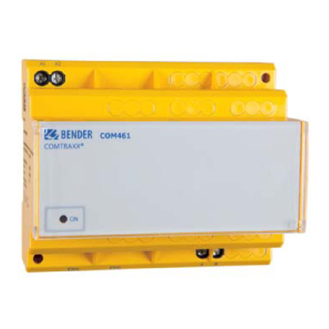
Bender COMTRAXX COM463BC User manual

Manual EN
COMTRAXX® COM463BC
Gateway for data exchange
between the interfaces BCOM and external BMS
Software version V4.7.x
COM463BC_D00427_02_M_XXEN/09.2023

2 COM463BC_D00427_02_M_XXEN/09.2023

COMTRAXX® COM463BC
Table of contents
1General information...........................................................................................5
1.1 How to use the manual.................................................................................................................................5
1.2 Indication of important instructions and information.......................................................................5
1.3 Signs and symbols...........................................................................................................................................5
1.4 Service and Support....................................................................................................................................... 5
1.5 Training courses and seminars...................................................................................................................6
1.6 Delivery conditions......................................................................................................................................... 6
1.7 Inspection, transport and storage.............................................................................................................6
1.8 Warranty and liability.....................................................................................................................................6
1.9 Disposal of Bender devices..........................................................................................................................7
1.10 Safety.................................................................................................................................................................... 7
2roduct description............................................................................................9
2.1 Scope of delivery............................................................................................................................................. 9
2.2 Device features................................................................................................................................................. 9
2.3 Applications....................................................................................................................................................... 9
2.4 Function...............................................................................................................................................................9
2.5 Functional description.................................................................................................................................10
2.5.1 Interfaces.......................................................................................................................................................... 10
2.5.2 BMS interface..................................................................................................................................................10
3Mounting, connection and commissioning................................................... 11
3.1 Preparation...................................................................................................................................................... 11
3.2 Installation and connection...................................................................................................................... 11
3.2.1 Mounting the device................................................................................................................................... 12
3.2.2 Connecting the device................................................................................................................................13
3.2.3 Wiring diagram...............................................................................................................................................14
3.3 Display and control elements.................................................................................................................. 15
3.4 Commissioning the device........................................................................................................................ 15
3.5 Factory settings for addresses..................................................................................................................16
4Web user interface........................................................................................... 17
4.1 Functions of the web user interface......................................................................................................17
4.2 Software products used..............................................................................................................................17
4.3 Browser configuration.................................................................................................................................17
4.4 Home page COMTRAXX® user interface...............................................................................................18
COM463BC_D00427_02_M_XXEN/09.2023 3

Table of contents
4.4.1 Headline............................................................................................................................................................18
4.4.2 Path display (breadcrumb navigation)................................................................................................. 18
4.4.3 Navigation........................................................................................................................................................19
4.4.4 Subnavigation.................................................................................................................................................19
4.4.5 Content area....................................................................................................................................................20
4.4.6 Overview of pending alarms.................................................................................................................... 20
5Virtual devices.................................................................................................. 21
5.1 Application possibilities..............................................................................................................................21
5.2 Managing virtual devices........................................................................................................................... 21
5.2.1 Virtual devices: Overview list/Main page.............................................................................................21
5.2.2 Editing a virtual device............................................................................................................................... 22
5.2.3 Editing channels............................................................................................................................................ 22
5.2.4 Deleting a device.......................................................................................................................................... 22
5.2.5 Adding a virtual device...............................................................................................................................22
6Troubleshooting............................................................................................... 24
6.1 Malfunctions....................................................................................................................................................24
6.1.1 What should be checked?..........................................................................................................................24
6.1.2 Frequently asked questions...................................................................................................................... 24
6.2 Device operation, maintenance, cleaning...........................................................................................24
7Technical data...................................................................................................25
7.1 Tabular data.................................................................................................................................................... 25
7.2 Standards, approvals and certifications................................................................................................28
7.3 Ordering information...................................................................................................................................28
7.4 Document revision history........................................................................................................................ 28
4 COM463BC_D00427_02_M_XXEN/09.2023

COMTRAXX® COM463BC
1 General information
1.1 How to use the manual
ADVICE
This manual is intended for qualified personnel working in electrical engineering and electronics!
Part of the device documentation in addition to this manual is the enclosed supplement "Safety
instructions for Bender products".
ADVICE
Read the operating manual before mounting, connecting and commissioning the device. Keep the
manual within easy reach for future reference.
1.2 Indication of important instructions and information
DANGER
Indicates a high risk of danger that will result in death or serious injury if not avoided.
WARNING
Indicates a medium risk of danger that can lead to death or serious injury if not avoided.
CAUTION
Indicates a low-level risk that can result in minor or moderate injury or damage to property if not
avoided.
ADVICE
Indicates important facts that do not result in immediate injuries. They can lead to malfunctions if the
device is handled incorrectly.
Information can help to optimise the use of the product.
1.3 Signs and symbols
Disposal Protect from moisture Protect from dust
Temperature range Recycling RoHS directives
1.4 Service and Support
Information and contact details about customer service, repair service or field service for Bender devices are
available on the following website: Fast assistance | Bender GmbH & Co. KG.
COM463BC_D00427_02_M_XXEN/09.2023 5

General information
1.5 Training courses and seminars
Regular face-to-face or online seminars for customers and other interested parties:
www.bender.de > know-how > seminars.
1.6 Delivery conditions
The conditions of sale and delivery set out by Bender GmbH & Co. KG apply. These can be obtained in printed
or electronic format.
The following applies to software products:
Die Elektroindustrie
‘Software clause in respect of the licensing of standard software as part of deliveries,
modifications and changes to general delivery conditions for products and services in the
electrical industry’
1.7 Inspection, transport and storage
Check the shipping and device packaging for transport damage and scope of delivery. In the event of
complaints, the company must be notified immediately, see "www.bender.de > service & support.".
The following must be observed when storing the devices:
1.8 Warranty and liability
Warranty and liability claims for personal injury and property damage are excluded in the case of:
•Improper use of the device.
•Incorrect mounting, commissioning, operation and maintenance of the device.
•Failure to observe the instructions in this operating manual regarding transport, commissioning, operation
and maintenance of the device.
•Unauthorised changes to the device made by parties other than the manufacturer.
•Non-observance of technical data.
•Repairs carried out incorrectly.
•The use of accessories or spare parts that are not provided, approved or recommended by the
manufacturer.
•Catastrophes caused by external influences and force majeure.
•Mounting and installation with device combinations not approved or recommended by the manufacturer.
This operating manual and the enclosed safety instructions must be observed by all persons working with the
device. Furthermore, the rules and regulations that apply for accident prevention at the place of use must be
observed.
6 COM463BC_D00427_02_M_XXEN/09.2023

COMTRAXX® COM463BC
1.9 Disposal of Bender devices
Abide by the national regulations and laws governing the disposal of this device.
For more information on the disposal of Bender devices, refer to
www.bender.de > service & support.
1.10 Safety
If the device is used outside the Federal Republic of Germany, the applicable local standards and regulations
must be complied with. In Europe, the European standard EN 50110 applies.
DANGER Risk of fatal injury due to electric shock!
Touching live parts of the system carries the risk of:
•Risk of electrocution due to electric shock
•Damage to the electrical installation
•Destruction of the device
Before installing the device and before working on its connections, make sure that the installation
has been de-energised. The rules for working on electrical systems must be observed.
COM463BC_D00427_02_M_XXEN/09.2023 7

Intended use
The COM463BC connects devices via the interfaces BCOM and external BMS. It is operated and configured
using the web user interface integrated into the device.
Address setting and termination
For proper functioning of the COM463BC correct address assignment and termination is of utmost importance.
CAUTION Malfunction due to duplicated addresses
Assigning addresses that are already used by existing devices in the bus systems concerned may cause
serious malfunctions.
Make sure the COM463BC is correctly addressed and terminated.
8 COM463BC_D00427_02_M_XXEN/09.2023

COMTRAXX® COM463BC
2 roduct description
This manual describes
•The gateway COMTRAXX® COM463BC.
2.1 Scope of delivery
Included within the scope of delivery
•A Gateway COM463BC
•A printed quick-start guide
•Safety instructions for Bender products
•The manuals ‘COMTRAXX® COM463BC’ and ‘BCOM’ are available as PDF files for download at https://
www.bender.de/en/service-support/download-area/
2.2 Device features
•Gateway for data exchange between the interfaces BCOM and external BMS
•Ethernet (10/100 Mbit/s) for remote access via LAN, WAN or the Internet
•Gateway with web interface
•Data exchange between devices at the following interfaces:
– External BMS bus (max. 99 x 150 devices)
– BCOM (max. 255 devices)
•Remote display of present measured values and operation/alarm messages
•Ethernet interface with 10/100 Mbit/s for remote access via LAN, WAN or the Internet
•Assignment of individual texts for devices, channels (measuring points) and alarms
•Device failure monitoring
•E-mail notifications to various users in the event of alarms and system errors
•100 virtual devices with 16 channels each can be created. These are used to transfer information from a
BCOM system to an external BMS system.
2.3 Applications
•Information exchange between BCOM and external BMS systems
•Configuration of the information to be transferred from one system to the other
•Several BMS-external systems can be displayed together with BCOM systems in one overview
•Selective notification to different users in case of alarms
•Remote diagnosis, remote maintenance
2.4 Function
The COM463BC gateways are integrated into the existing EDP structure like PCs. After connecting to the
network and compatible Bender products, all system devices can be accessed from any PC using a web
browser. In this way, all important system information is directly available.
Verified web browsers: Microsoft Edge, Mozilla Firefox, Google Chrome.
COM463BC_D00427_02_M_XXEN/09.2023 9

Product description
2.5 Functional description
2.5.1 Interfaces
The COM463BC communicates via the following interfaces:
•External BMS (RS-485)
•BCOM (Ethernet)
Image 2-1: Application example
2.5.2 BMS interface
External BMS bus (BMSe)
Individual Bender devices, such as MK800, TM800 or Bender panels can communicate via the external BMS bus
(BMSe).
The COM463BC can communicate via the external BMS bus (BMSe).
The COM463BC cannot parameterise other bus devices on the external bus. The parameters of the COM463BC
itself can, however, be set via the LAN connected.
Note that not all B S masters can surrender their master function!
10 COM463BC_D00427_02_M_XXEN/09.2023

COMTRAXX® COM463BC
3 Mounting, connection and commissioning
The COM463BC is normally integrated into existing LAN structures, but can also be operated via a single PC on
the Ethernet side.
CAUTION
If you are familiar with the configuration of computer networks, you can carry out the connection of the
CO 463BC yourself. Otherwise please contact your ED administrator!
3.1 reparation
1. Have all the questions concerning the installation been discussed with the technician responsible for the
installation?
2. Is the BMS address to be set known?
For more detailed information on the topic of BMS, in particular about the wiring of bus devices, please
refer to the separate document "BMS bus". You can obtain this document at
https://www.bender.de/en/service-support/download-area/
3. Does the computer network have a DHCP server?
If the connected computer network contains a DHCP server, activate the ‘DHCP’ function. The IP address is
automatically assigned and displayed.
If the computer network does not include a DHCP server, the IP address, network mask (SN) and standard
gateway must be specified by the EDP administrator. The IP address has been permanently assigned to the
device. Therefore, deactivate the ‘DHCP’ function on the gateway.
4. Ask for the IP address of the NTP server; it is required for the automatic time setting.
5. Are suitable PC hardware and software available for commissioning?
- System requirements (minimum): 1.6 GHz processor/512 MB RAM
- Verified web browsers: Microsoft Edge, Mozilla Firefox, Google Chrome
For initial connection, the basic configuration of the CO 463BC is to be undertaken outside the
installation, depending on the specific situation.
3.2 Installation and connection
Only skilled persons are permitted to carry out the work necessary to install, put into service and run a
device or system.
DANGER Risk of fatal injury due to electric shock!
Touching live parts of the system carries the risk of:
•Risk of electrocution due to electric shock
•Damage to the electrical installation
•Destruction of the device
Before installing and connecting the device, make sure that the installation has been de-energised.
The rules for working on electrical systems must be observed.
COM463BC_D00427_02_M_XXEN/09.2023 11

Mounting, connection and commissioning
DANGER Mortal danger and risk of irreparable damage due to moisture!
Install device such that it is protected against moisture.
CAUTION
ay attention to installation location
Operation of the device is only permitted in operating locations with restricted access! This can be
installation in a switch cabinet, for example.
3.2.1 Mounting the device
The device is suitable for the following types of installation:
•Snap-on mounting on a DIN rail according to IEC 60715 or
•Screw mounting using 3 x M4
Snap-on mounting on a DIN
rail according to IEC 60715
Screw mounting using 3 x M4
Dimension diagram (mm)
107,5
45
62,9
48,5
93
40
62 33
12 COM463BC_D00427_02_M_XXEN/09.2023

COMTRAXX® COM463BC
3.2.2 Connecting the device
Element Explanation
A1/+; A2/- Power supply
Plug X1 BMS bus (Bender measuring device interface): Terminals ABMS and BBMS
Plug X2 Et ernet connection (RJ45) for t e connection to t e PC network as well as to BCOM
RBMS BMS bus terminating resistor switc
Make the connection as follows:
1. Remove terminal covers of the device.
2. BMS bus connection
Connect the terminals ABMS and BBMS to the BMS bus (A to A, B to B). If the COM463BC is at the end of
the BMS bus, you must switch the terminating switch RBMS on the device to "ON‘.
3. Ethernet connection (BCOM)
Connect Ethernet cable (RJ45) to the COM463BC and connect to the network. It is recommended to use at
least on Ethernet cable of category 5 (Cat. 5).
4. Connect power supply
Connect terminals A1/+ and A2/- to a power supply. The power supply must be protected using a 6 A fuse.
5. Position the terminal covers and click it into place.
COM463BC_D00427_02_M_XXEN/09.2023 13

Mounting, connection and commissioning
3.2.3 Wiring diagram
Wiring diagram COM463BC (example)
14 COM463BC_D00427_02_M_XXEN/09.2023

COMTRAXX® COM463BC
3.3 Display and control elements
COM463BC
LED Function
ON ‘ON’ LED: Flas es during t e start process. T e LED lig ts continuously as soon as t e device is ready
for operation.
BCOM
BMS LEDs indicate activity on t e various interfaces.
3.4 Commissioning the device
1. Switch on the supply voltage: When the device is supplied with power, all LEDs light up briefly. During the
start process the ‘ON’ LED flashes. After a successful start, the ‘ON’ LED then illuminates continuously. The
device is now ready for operation.
2. Start web user interface:
– Open an internet browser.
– Type the following IP address to open the web interface of the COM46…:
uIf your PC is in a 192.168.0.0 IT subnet, you can reach the COM46… via the factory-set IP address
192.168.0.254.
uIf your PC is in a different subnet, you must disconnect the PC from your network. Connect the
COM46… directly to your PC. Open the web user interface using the second pre-defined I address:
169.254.0.1. For this purpose, DHCP must be enabled on the PC.
In the web user interface, the IP address of the COM46… can be set as required.
3. Configure: As a minimum, configure all address data for the COM46…. Always configure the BCOM
interface (system name, subsystem, device address).
Risk of duplicate addresses if BCOM system name is not changed.
The factory setting for the system name on all Bender BCO devices is "SYSTE ". If several systems
are established in the same network, there is a risk that addresses will be assigned more than once.
Therefore always give each system a new BCOM system name during commissioning.
4. Integrate devices into the system:
COM463BC_D00427_02_M_XXEN/09.2023 15

Mounting, connection and commissioning
– BCOM devices are detected automatically
5. Check connection
Connect the COM46… to the network again. Start the web user interface. All other settings (individual
texts, e-mail notifications, …) can now be made.
3.5 Factory settings for addresses
The COM463BC is supplied with the following factory settings:
Parameter Factory setting
IP address 192.168.0.254
Connection can always be made using t e pre-defined IP address (e.g. for
commissioning) 169.254.0.1
Net mask 255.255.0.0
Standard gateway 192.168.0.1
DNS 194.25.2.129
DHCP off
toff (Timeout for DHCP address assignment) 30 s
BMS address 1
BMS protocol BMS e
BCOM system name SYSTEM
Subsystem address 1
BCOM device address 0 (= off)
The settings can be changed using the web user interface.
16 COM463BC_D00427_02_M_XXEN/09.2023

COMTRAXX® COM463BC
4 Web user interface
The web user interface of the device enables access via LAN, WLAN or the Internet. It provides a uniform
display of all connected Bender devices.
4.1 Functions of the web user interface
•Bus overview of the associated devices
•Indicating alarms and measured values
•Display by interface or subsystem
•Device failure monitoring
•Saving settings as ‘backup’ and restoring values again
•Documenting settings and measured values
•Assigning individual texts for devices, measuring points (channels) and alarms
•E-mail notifications to different user groups according to a time-controlled schedule in the event of alarms
and system errors. The sender's e-mail address can be entered.
•Display of virtual devices. A virtual ‘measuring point’ is obtained by logically or numerically evaluating
measured values of ‘real’ devices connected to the gateway.
4.2 Software products used
Select Tools > Information > Copyrigh to display the used software products.
4.3 Browser configuration
As browser, the latest version of Google Chrome, Microsoft Edge and Mozilla Firefox are recommended. To
use the functions of the web user interface, JavaScript has to be activated. The pop-up blocker should be
deactivated for the IP address of the COMTRAXX® device.
For Windows© Internet Explorer, the compatibility view has to be disabled.
Select Extras > Configuration of compatibility view. Deactivate the button Display Intranet sites in
compatibility view.
COM463BC_D00427_02_M_XXEN/09.2023 17

Web user interface
4.4 Home page COMTRAXX® user interface
1. Open an Internet browser.
2. Enter the IP address of the gateway in the address line (example: http://172.16.60.72).
1 Headline
2 Path display
3 Navigation
4 Subnavigation
5 Content area
6 Alarm overview
4.4.1 Headline
1 Clicking the logo: Return to home page
2 Used device: Device type
3 Used device: System name > Subsystem > Device address
Date and time of the device
4 The symbol indicates that the web user interface is protected by a password. Click
the symbol and then click Login to enter the user name and password.
5 Language selection
6 Open/close navigation (button only available in small browser window)
4.4.2 ath display (breadcrumb navigation)
1= Device
The path display shows at any time on which device and in which bus you are currently located in the content
window.
18 COM463BC_D00427_02_M_XXEN/09.2023

COMTRAXX® COM463BC
4.4.3 Navigation
Menu escription
Start Display of information about t e device and t e software. Please ave t is
information to and if you need to contact us for assistance by telep one.
System overview T e system overview s ows all devices in t e system eit er by subsystem or
by interface. Pending alarms and operating messages are displayed and t e
respective devices can also be configured.
Alarms Display of all pending alarms and data of t e devices sending an alarm
Tools Functions t at affect t e entire system
The navigation symbols are permanently visible on the left side. Even if a random submenu of the web user
interface is open, you can navigate to one of the four areas by clicking the respective symbol.
4.4.4 Subnavigation
The system overview is displayed in the subnavigation.
Legend
1. Full text search in the system for device names or menu entries. Matches are highlighted in yellow.
2. Close unfolded tree in the subnavigation
3. Fold out automatically: When enabled (= yellow), the displayed contents of the content area are shown in
the subnavigation with automatically unfolding device tree in addition to the path display. Path display
and content area are always synchronous. When disabled (= white), the subnavigation is not adapted to
the path display or the current content area.
4. - Select display by subsystems or by interfaces. The interface display is only available for COMTRAXX®
V4.xx and higher.
- Configure the line height of the entries.
5. The number in brackets (here: 25) indicates the set bus address.
The display by subsystem or interface is possible independently of the configured odbus image V1 or V2.
COM463BC_D00427_02_M_XXEN/09.2023 19

Web user interface
4.4.5 Content area
Display of the system, alarms and entries for the tools .
Content area of the system display by
subsystem
Content area of the system display by
interface
4.4.6 Overview of pending alarms
Clicking the alarm overview: List of pending alarms
Clicking on the list: Details about the alarms in the content area
20 COM463BC_D00427_02_M_XXEN/09.2023
Other manuals for COMTRAXX COM463BC
3
Table of contents
Other Bender Gateway manuals

Bender
Bender COMTRAXX COM460IP User manual

Bender
Bender COM465IP User manual

Bender
Bender COM461MT User manual

Bender
Bender COMTRAXX COM465ID User manual

Bender
Bender COMTRAXX COM462RTU User manual

Bender
Bender COMTRAXX COM463BC User manual

Bender
Bender COMTRAXX COM463BC User manual

Bender
Bender COMTRAXX COM463BC User manual

Bender
Bender COM465IP User manual

Bender
Bender COMTRAXX COM462RTU User manual