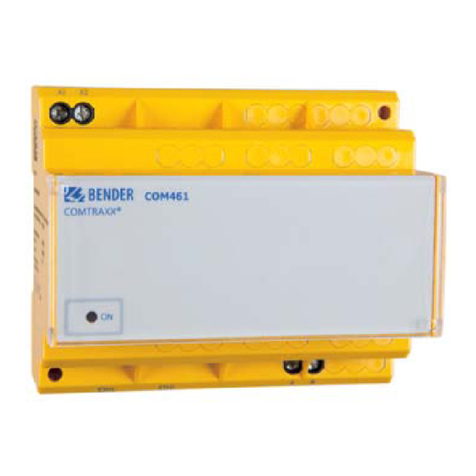
Bender COMTRAXX COM462RTU User manual

Manual ENCOM462RTU_D00010_04_M_XXDE / 06.2021
COMTRAXX® COM462RTU
BMS-Modbus RTU gateway for the connection of BMS-capable Bender
devices to the Modbus RTU
Software version: D0415 V1.2x

2 COM462RTU_D00010_04_M_XXDE / 06.2021
Service and support for Bender products
First-level support
Technical support
Carl-Benz-Strasse 8 • 35305 Grünberg • Germany
Telephone: +49 6401 807-760
0700BenderHelp *
Fax: +49 6401 807-629
E-mail: support@bender-service.de
Available on 365 days from 7.00 a.m. to 8.00 p.m. (MEZ/UTC +1)
* Landline German Telekom: Mon-Fri from 9.00 a.m. to 6 p.m.: 6.3 cents/30 sec.; remaining time:
6.3 cents/min.
Repair service
Repair, calibration and replacement service
Londorfer Strasse 65 • 35305 Grünberg • Germany
Telephone: +49 6401 807-780 (technical issues) or
+49 6401 807-784, -785 (commercial issues)
Fax: +49 6401 807-789
E-mail: [email protected]
Field service
On-site service
Telephone: +49 6401 807-752, -762 (technical issues) or
+49 6401 807-753 (commercial issues)
Fax: +49 6401 807-759
E-mail: fieldservice@bender-service.de
Mon-Thu 7.00 a.m. to 4.00 p.m., Fri 7.00 a.m. to 1 p.m. (MEZ/UTC +1)

COM462RTU_D00010_04_M_XXDE / 06.2021 3
COMTRAXX® COM462RTU
Table of Contents
1 General instructions ..........................................................................5
1.1 How to use this manual..............................................................................................5
1.2 Indication of important instructions and information....................................5
1.2.1 Signs and symbols ........................................................................................................5
1.3 Training courses and seminars.................................................................................5
1.4 Delivery conditions.......................................................................................................5
1.5 Inspection, transport and storage ..........................................................................6
1.6 Warranty and liability...................................................................................................6
1.7 Disposal of Bender devices........................................................................................6
1.8 Safety .................................................................................................................................7
2 Product description ...........................................................................8
2.1 Intended use...................................................................................................................8
2.2 Address setting and termination ............................................................................8
2.3 Scope of delivery...........................................................................................................8
2.4 Short description...........................................................................................................8
2.5 Device features ..............................................................................................................9
2.6 Possible applications ...................................................................................................9
2.7 Details about the Modbus RTU................................................................................9
3 Installation, connection and commissioning ............................ 10
3.1 Preliminary considerations..................................................................................... 10
3.2 COM462RTU on the internal BMS bus................................................................ 10
3.3 Installing the device..................................................................................................11
3.4 Connecting the device.............................................................................................11
3.5 Commissioning ...........................................................................................................13
4 Operation and configuration........................................................ 14
4.1 Display and operating elements .......................................................................... 14
4.1.1 Automatic contrast setting for the display....................................................... 14
4.1.2 Display in standard mode.......................................................................................15
4.1.3 Display in menu mode............................................................................................. 15
4.2 Factory settings...........................................................................................................16
4.3 Settings on the device.............................................................................................. 16
4.3.1 Operating example: Setting BMS address ........................................................ 16
4.4 Display INFO list.......................................................................................................... 18
5 Data access using Modbus RTU protocol................................... 19
5.1 Exception code ...........................................................................................................19
5.2 Modbus requests........................................................................................................ 19
5.3 Modbus responses..................................................................................................... 20
5.4 Structure of the exception code........................................................................... 20
5.5 Modbus address structure for BMS devices.....................................................20

4 COM462RTU_D00010_04_M_XXDE / 06.2021
6 Modbus process image in the memory of the COM462RTU .. 21
6.1 Querying data..............................................................................................................21
6.1.1 Modbus function code............................................................................................. 21
6.1.2 How are the memory areas organised?.............................................................21
6.2 Memory scheme of the process image..............................................................22
6.2.1 BMS device address assignment on the Modbus .......................................... 22
6.2.2 Memory scheme of an individual BMS device ................................................ 22
6.2.3 Device type...................................................................................................................24
6.2.4 Timestamp....................................................................................................................24
6.2.5 Common alarm and device failure ...................................................................... 25
6.2.6 Channels 1 to 32 with analogue and/or digital values ................................ 25
6.2.6.1 Float = Floating point value of the BMS channels....................................................25
6.2.6.2 AT&T = Alarm type and test type (internal/external)...............................................26
6.2.6.3 R&U = Bereich und Einheit.................................................................................................27
6.2.6.4 Channel description .............................................................................................................28
6.2.6.5 Channel 33 to 64....................................................................................................................29
6.3 Reference data records of the process image.................................................29
6.3.1 Address assignment of the reference data record ........................................ 30
6.3.2 Reference value on channel 1 ............................................................................... 30
6.3.3 Reference value on channel 2 ............................................................................... 30
6.3.4 Explanation of how to access floating point values .....................................31
6.4 Channel descriptions for the process image ................................................... 31
6.5 Modbus control commands...................................................................................37
7 Technical data.................................................................................. 40
7.1 Tabular data .................................................................................................................40
7.2 Dimension diagram................................................................................................... 41
7.3 Standards, approvals, certifications ....................................................................42
7.4 Ordering details.......................................................................................................... 42
8 Troubleshooting.............................................................................. 43
8.1 Malfunctions ................................................................................................................43
8.2 What should be checked?.......................................................................................43
8.3 Where to find help?................................................................................................... 43

COM462RTU_D00010_04_M_XXDE / 06.2021 5
COMTRAXX® COM462RTU
1 General instructions
1.1 How to use this manual
This manual is intended for qualified personnel working in electrical engineering and elec
tronics! Part of the device documentation, in addition to this manual, is the enclosed
“Safety instructions for Bender products”.
Read the manual before installing, connecting and commissioning the device.
Always keep the manual within easy reach for future reference.
1.2 Indication of important instructions and information
I Danger! Indicates a high risk of danger that will result in death or serious injury if
not avoided.
I Warning! Indicates a medium risk of danger that can lead to death or serious injury, if
not avoided.
I Caution! Indicates a low-level risk that can result in minor or moderate
injury or damage to property if not avoided.
i
Information can help to optimise the use of the product.
1.2.1 Signs and symbols
Disposal Temperature range protect from dust
protect from wetness Recycling RoHS
guidelines
1.3 Training courses and seminars
www.bender.de > Know-how-> Seminars.
1.4 Delivery conditions
The conditions of sale and delivery set out by Bender apply. These can be obtained from Bender
in printed or electronic format. The following applies to software products:
“Software clause in respect of the licensing of standard software as part of
deliveries, modifications and changes to general delivery conditions for
products and services in the electrical industry.”
Die Elektroindustrie

6 COM462RTU_D00010_04_M_XXDE / 06.2021
General instructions
1.5 Inspection, transport and storage
Check the shipping and device packaging for transport damage and scope of delivery.
The following must be observed when storing the devices:
1.6 Warranty and liability
Warranty and liability claims in the event of injury to persons or damage to property are excluded
in case of:
• Improper use of the device.
• Incorrect mounting, commissioning, operation and maintenance of the device.
• Failure to observe the instructions in this operating manual regarding transport, com-
missioning, operation and maintenance of the device.
• Unauthorised changes to the device made by parties other than the manufacturer.
• Non-observance of technical data.
• Repairs carried out incorrectly.
• Use of accessories and spare parts not recommended by Bender.
• Catastrophes caused by external influences and force majeure.
• Mounting and installation with device combinations not recommended by the
manufacturer.
This operating manual and the enclosed safety instructions must be observed by all persons
working with the device. Furthermore, the rules and regulations that apply for accident
prevention at the place of use must be observed.
1.7 Disposal of Bender devices
Abide by the national regulations and laws governing the disposal of this device.
For more information on the disposal of Bender devices, refer to
www.bender.de -> Service & support.

COM462RTU_D00010_04_M_XXDE / 06.2021 7
COMTRAXX® COM462RTU
1.8 Safety
If the device is used outside the Federal Republic of Germany, the applicable local standards and
regulations must be complied with. In Europe, the European standard EN 50110 applies.
I Danger! Risk of electrocution due to electric shock!
Touching live parts of the system carries the risk of
• A fatal electric shock
• Damage to the electrical installation
• Destruction of the device
Before installing and connecting the device, make sure that the installation has been
de-energised. The rules for working on electrical systems must be observed.

8 COM462RTU_D00010_04_M_XXDE / 06.2021
Product description
2 Product description
2.1 Intended use
The BMS-Modbus RTU gateway COM462RTU connects the serial Bender BMS bus to the serial
Modbus RTU. The gateway converts alarms, measured values and statuses from the BMS bus to
Modbus RTU. Control commands can be converted from Modbus RTU to BMS bus.
This allows connection to Modbus networks. The gateway is operated on the internal BMS bus.
2.2 Address setting and termination
In order to ensure proper functioning of the BMS-Modbus RTU gateway COM462RTU, correct
address assignment and termination of the BMS bus and the Modbus RTU is of utmost
importance.
I Caution! Assigning addresses that are already used by existing devices in the BMS or Modbus
RTU networks concerned may cause serious malfunctions.
Ensure correct address setting and termination of the COM462RTU. For details refer to
„Inbetriebnahme“ auf Seite 22.
Interface on the Modbus RTU side
i
The COM462RTU is always operated as slave on the Modbus RTU side. Therefore, the
COM462RTU and its Modbus RTU has to be communicated to the Modbus RTU master.
Interface on the BMS side
COM462RTU can be operated as master or slave.
2.3 Scope of delivery
You will receive:
• the COM462RTU
• an operating manual
2.4 Short description
The BMS-Modbus RTU gateway COM462RTU contains a Modbus RTU slave that converts BMS data
for a Modbus master.
A setting menu makes it possible to configure the COM462RTU using the setting menu (see
„Commissioning“ auf Seite 13).

COM462RTU_D00010_04_M_XXDE / 06.2021 9
COMTRAXX® COM462RTU
2.5 Device features
• Setting of address data for the BMS bus and Modbus RTU and date and time setting
using the internal operating menu.
• Time synchronisation for all BMS bus devices
• Operation on the internal BMS bus
• Modbus RTU data access to the internal BMS bus, max. 150 BMS devices
• Commands can be sent from an external application (e.g. visualisation software) to BMS
devices and measured values read.
2.6 Possible applications
• The use of professional visualisation programs by converting BMS data to Modbus RTU
protocols.
• Observing and analysing Bender products that support communication, such as RCMS,
EDS and MEDICS® systems.
2.7 Details about the Modbus RTU
The Modbus RTU (Remote Terminal Unit) field bus has been specified by Modicon, a company
under the Schneider Automation brand and made available to the market license-free.
Modbus uses the serial hardware interface RS-485 and communicates via a two-wire, twisted
copper wire. A transmission rate of 19200 baud is standard.
• Master-slave communication
• Up to 32 bus devices per network, or up to 247 bus devices (with repeater)
• Baud rate between 1200 and 57600 bit/s
• Diagnostics mechanisms

10 COM462RTU_D00010_04_M_XXDE / 06.2021
Installation, connection and commissioning
3 Installation, connection and commissioning
i
If you are familiar with the configuration of Modbus RTU networks, you can carry out the
connection of the COM462RTU by yourself. Otherwise please contact your EDP
administrator!
3.1 Preliminary considerations
1. Have all the questions as regards the installation been answered by the technician
responsible for the installation?
2. The device is operated on the internal bus. Is the BMS address to be set known?
If, apart from the COM462RTU, an alarm indicator and test combination MK800 is
connected to the internal bus, the COM462RTU must not have the address 1 (master).
You will find more detailed information on the BMS topic, in particular about the wiring
of bus devices, in the separate document "BMS bus". You can download the document
from the download area of the website www.bender.de.
3. Is the Modbus RTU address to be set known?
3.2 COM462RTU on the internal BMS bus
Bender systems such as EDS46x/49x, RCMS46x/49x and MEDICS communicate with each other via
the Bender measuring device interface BMS.
The BMS-Modbus RTU gateway COM462RTU provides the coupling between the BMS bus and
Modbus RTU networks. The following block diagram illustrates the operation of the gateway in an
internal BMS bus..
Abb. 3–1 Block diagram of a coupling between an internal BMS bus and Modbus RTU
COM462RTU
D+ D- D- D-D+ D+
D-D+
Modbus/RTU

COM462RTU_D00010_04_M_XXDE / 06.2021 11
COMTRAXX® COM462RTU
i
Internal and external BMS bus
The majority of Bender devices communicate via the internal BMS bus. Individual
devices, such as MK800, TM800 or Bender panels can communicate via both the internal
BMS bus (BMS i) and the external BMS bus (BMS e). The BMS-Modbus RTU gateway
COM462RTU can only communicate via the internal BMS bus (BMS i).
3.3 Installing the device
Possible methods of mounting:
• DIN rail mounting
• Screw mounting with 2 x M4 (dimension diagram on Seite 41)
i
When installing the device, please take into consideration that the device is only to be
used in locations that are protected from unauthorised entry! This can be installation in
a switch cabinet, for example.
3.4 Connecting the device
For UL applications, the following is to be observed:
• Supply voltage Us: see nameplate and ordering details
• Maximum ambient temperature: 55°C
• For use in pollution degree 2 environments
• Use 60/70°C copper lines only
• Tightening torque for terminals: 0.5…0.6 Nm

12 COM462RTU_D00010_04_M_XXDE / 06.2021
Installation, connection and commissioning
Connect the terminals and sockets on the COM462RTU according to the wiring diagram.
Terminal Description
A1, A2 Connection to the supply voltage, 6 A fuse recommended, two-pole fuses should be used in IT systems.
For UL and CSA applications, it is mandatory to use 5 A fuses.
A, B Connection to the BMS bus (internal) with shielded cable
(e.g. J-Y(St)Y 2x0.8).
AMB, BMB Connection Modbus RTU with shielded cable
(z. B. J-Y(St)Y 2x0.8).
Ron/off
(A, B)
Switch for BMS bus termination. When the device is installed at the end of the bus, set the terminating switch
to "on".
RMBon/off
(AMB, BMB)
Switch for Modbus RTU termination.When the device is installed at the end of the bus, set the terminating
switch to "on".
IN1,
GND1/2,
IN2
Currently has no function (digital inputs)
11, 14 Currently has no function (alarm relay K1)
IN3,
GND3/4
IN4
Currently has no function (digital inputs)
A1 A2
AB
IN3 IN4
GND
3/4 BMB
AMB
IN1 IN2
GND
1/2 14
11
A2
A1
6 A 6 A
US
RMB
(AMB, BMB)
BMS-Bus
RS-485
Modbus/RTU
RS-485
AMB BMB
ALARM
COM
ON MENU
INFO
ESC

COM462RTU_D00010_04_M_XXDE / 06.2021 13
COMTRAXX® COM462RTU
3.5 Commissioning
1. Apply the supply voltage to the COM462RTU. The green "ON" LED lights up.
2. Set language and time.
3. Set the BMS bus. The COM462RTU is operated on the internal BMS bus.
4. Set the Modbus RTU.
For details about the settings, refer to the chapter „Settings on the device“ auf Seite 16.

14 COM462RTU_D00010_04_M_XXDE / 06.2021
Operation and configuration
4 Operation and configuration
4.1 Display and operating elements
Legend
1"ON“ LED lights when supply voltage is applied.
2"COM" LED lights when the gateway is responding to BMS requests.
3"ALARM“ LED, lights to signal an internal device error on the COM462RTU.
4"INFO" button, to query the COM462RTU for device-specific information.
"ESC" button to exit the menu function without changing parameters.
5„p“ button: to move up in the menu, to increase values
6„q“ button: to move down in the menu, to decrease values
7"MENU" button for starting and exiting the menu.
„ “ button to confirm parameter change.
8LC display for standard and menu mode.
4.1.1 Automatic contrast setting for the display
The display contrast control is factory set to an optimum value. In exceptional cases, it may be
necessary to adjust the contrast manually.
Press and hold the buttons "ESC" and „ “ simultaneously. All available contrast modes are
continuously indicated in an infinite loop: minimum contrast, maximum contrast, no contrast
(lasting some seconds), then the same cycle starts again. If the button „q“ is additionally pressed,
the contrast modes will be displayed in the opposite direction.
Release the button as soon as the desired level of contrast is reached.
ALARM
COM
ON MENU
INFO
ESC
COMTRAXX®
COM462
3
2
1
4
5
6
7
8

COM462RTU_D00010_04_M_XXDE / 06.2021 15
COMTRAXX® COM462RTU
4.1.2 Display in standard mode
Network-related parameters will be indicated.
Legend
1Device type
2BMS address of the COM462RTU
3Modbus address of the COM462RTU
4Current date and time
4.1.3 Display in menu mode
Use the "MENU" button to switch to the Menu mode.
A blinking cursor supports menu navigation.
• You can access the individual menus by means of the „p“ or „q“ button.
• Press the „ “ button to confirm the selection of a menu or any setting you changed.
• To leave the respective menu level or discard a setting which is not confirmed yet, press
the "ESC" button.
i
Menu mode is exited if no button is pressed for longer than five minutes.
1
2
3
4
COM462RTU
Address:1
Modbus:240
22.06.2013 12:34
Exit
1. Settings
2. Info

16 COM462RTU_D00010_04_M_XXDE / 06.2021
Operation and configuration
Menu item Function Page
Exit Exit menu mode
1. Settings Make the necessary settings for this
device
16
2. Info Display information on device type and
firmware versions.The same informa-
tion as indicated in the standard mode
when pressing the "INFO" button.
18
4.2 Factory settings
All factory settings you will find in the table on Seite 17.
4.3 Settings on the device
The menu is divided into three levels. All menu items listed in the table can be called up via the
main menu item "1. Settings" in the top menu level. All control buttons are explained on Seite
14.
4.3.1 Operating example: Setting BMS address
The following example shows the operating principle. All settings are carried out in the same way.
1. Press the "MENU" button on the COM462RTU.
2. Select "1. Settings" > "1. Interface" > "1. Address". The factory-set BMS address will be
displayed and can be changed now.
3. Modify the addresses using the button „p“ or „q“.
4. Confirm the modified BMS address with „ ”.

COM462RTU_D00010_04_M_XXDE / 06.2021 17
COMTRAXX® COM462RTU
Menu level 2 Menu level 3 Factory setting Description
1. Interface 1. Address 2 Set the BMS address of COM462RTU: 1…99
(internal BMS bus)
2. Interval 2 s Set the cycle time 1…3s for the sequence:
• Querying alarms in the BMS bus
• Querying new bus devices
• Offering the BMS master function
3. Failure monitoring 5 Number of BMS bus cycles until a BMS device
failure is signalled.The setting is only effec-
tive when the COM462RTU has the master
function on the BMS bus (address 1).
Adjustable cycles: 1…10
2. Modbus 1. Address 2 Set the Modbus RTU address for COM462RTU:
2…247
2. Baud rate 19200 Set the baud rate
3. Parity even Set the parity
4. Control off Switch on or switch off the control commands
via Modbus
3. Language 1. English Deutsch Selection of the operating language
2. Deutsch
3. Français
4. Clock 1. Format d.m.y Date format: m-d-y/d.m.y
2. Date 01.01.2010 Date
3. Time 00:00 Time
4. Summertime off Select Central European SummerTime:
off = Function switched off
DST = Automatic switchover, USA, CDN
CEST = Automatic switchover, Central Europe
on = Set time zone +1 h
5. Password 1. Password 000 Enter/change password: 0…999
2. Status off Enable/disable password protection for
parameter setting via the buttons of the
COM462RTU
6. Service For authorised Bender Service personnel only.

18 COM462RTU_D00010_04_M_XXDE / 06.2021
Operation and configuration
4.4 Display INFO list
Open the "INFO" menu:
• In standard mode: press the "INFO" button or
• In menu mode: select function "2. Info"
This menu displays information about the device and the software. Navigate in the list using the
„q“ resp. the „p“ button.
1. Name of the device
2. BMS address
3. Order number
4. Serial number
5. Software version
6. Manufacturer's address
Please have this information to hand if you need to contact us for assistance by telephone.
COM462RTU
Address:1
Device:B95061022
S:0123456789

COM462RTU_D00010_04_M_XXDE / 06.2021 19
COMTRAXX® COM462RTU
5 Data access using Modbus RTU protocol
Request to the COM462RTU are sent using the function code 0x03 (Read Holding Registers). The
COM462RTU generates a function-related response and returns it.
5.1 Exception code
If a request cannot be answered for whatever reason, the COM462RTU sends a so-called
exception code with which possible faults can be narrowed down.
Exception code Description
0x01 Impermissible function
0x02 Impermissible data access
0x03 Impermissible data value
0x04 Slave device error
0x05 Acknowledgement of receipt (answer will be time-delayed)
0x06 Request not accepted (repeat request, if necessary)
0x08 Memory: Parity Error
0x0A Gateway path not available
0x0B Gateway error
5.2 Modbus requests
The required words of the process image can be read from the "Holding Registers" in the
COM462RTU using the function code 0x03. For this purpose, the start address and the number of
the registers to be read out have to be entered.
A complete bus image including all devices and device parameters is stored in these "Holding
Registers". This image represents the current statuses and values of up to 150 BMS devices for
each monitored internal BMS bus. The operating manuals of the devices indicate which channel
contains which information. Example: In the table below, Words 0 and 1 are to be read out from
the "Holding Registers“ 0x100 and 0x101.
Byte Name Example
Byte 0 BMS address of the COM462RTU 0x02
Byte 1 Function code 0x03
Byte 2, 3 Start address 0x01 00
Byte 4, 5 Number of registers 0x00 02
Byte 6, 7 CRC16 0x12 34

20 COM462RTU_D00010_04_M_XXDE / 06.2021
Data access using Modbus RTU protocol
5.3 Modbus responses
The responses consist of 2 bytes per register.
Byte Name Example
Byte 0 BMS address of the COM462RTU 0x02
Byte 1 Function code 0x03
Byte 2 Number of data bytes 0x04
Byte 3…6 Information 0xAB CD 01 23
Byte 7, 8 CRC16 0x12 34
5.4 Structure of the exception code
Byte Name Example
Byte 0 BMS address of the COM462RTU 0x02
Byte 1 Function code (0x03) + 0x80 0x83
Byte 2 Data 0x04
Byte 3, 4 CRC16 0x12 34
5.5 Modbus address structure for BMS devices
Function Address range Number of bytes Number of words
Device type 0x00…0x09 20 bytes 10 words
Timestamp 0x0A…0x0D 8 bytes 4 words
Common alarm 0x0E
(High byte)
1 byte 0.5 words
No BMS bus connection 0x0E
(Low byte)
1 byte 0.5 words
Unused 0x0F 2 bytes 1 word
Channel 1…32 0x10…0x8F 32 x 8 bytes 128 words
Alarm and test
Channel 33…64
0x90…0xFC 218 x 8 bytes 109 words
Other manuals for COMTRAXX COM462RTU
1
Table of contents
Other Bender Gateway manuals
Bender
Bender COMTRAXX COM463BC User manual
Bender
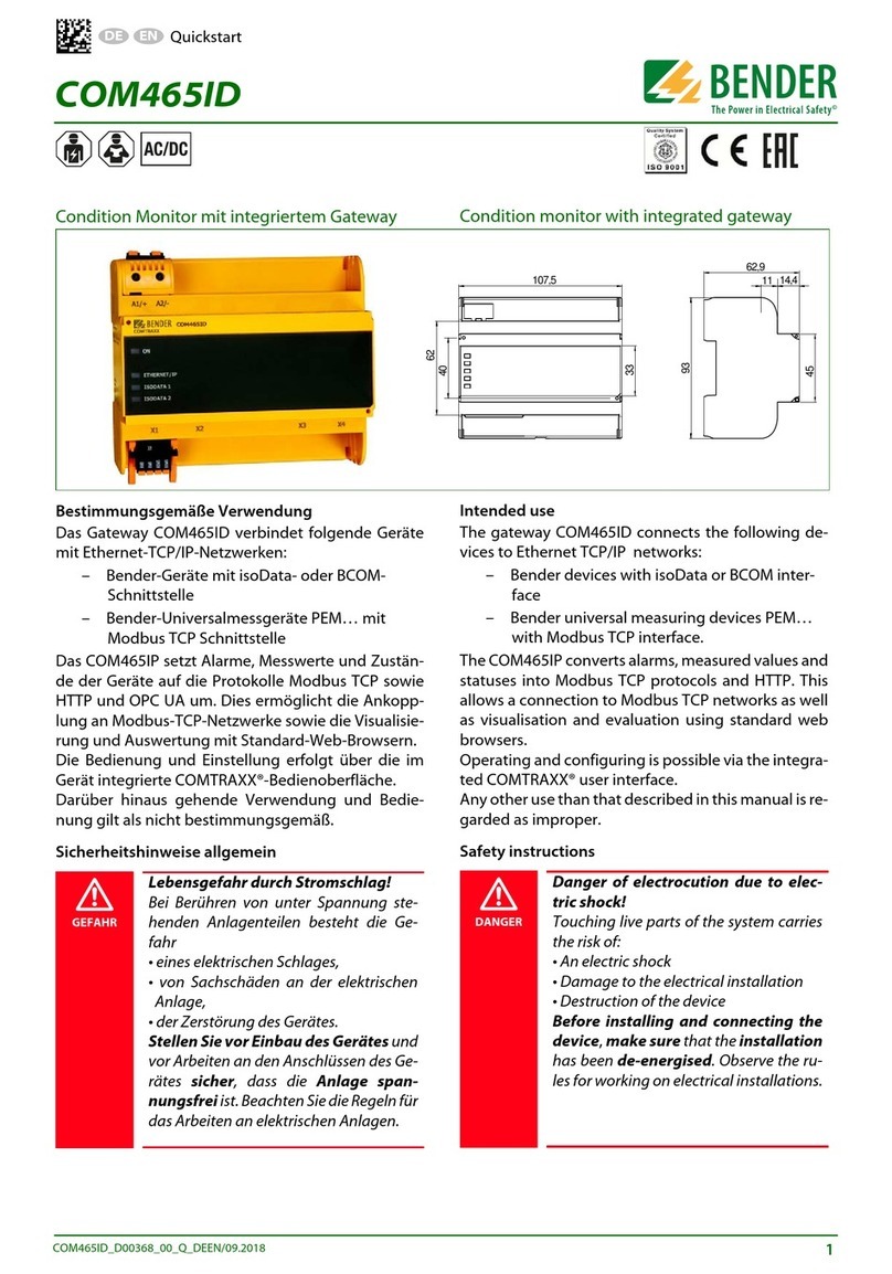
Bender COMTRAXX COM465ID User manual

Bender
Bender COMTRAXX COM460IP User manual

Bender
Bender COM465IP User manual
Bender
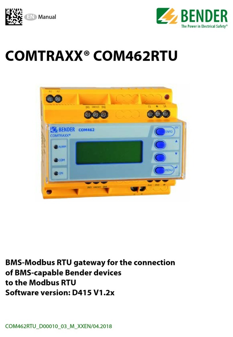
Bender COMTRAXX COM462RTU User manual

Bender
Bender COM465IP User manual

Bender
Bender COMTRAXX COM463BC User manual

Bender
Bender COMTRAXX COM463BC User manual
Bender
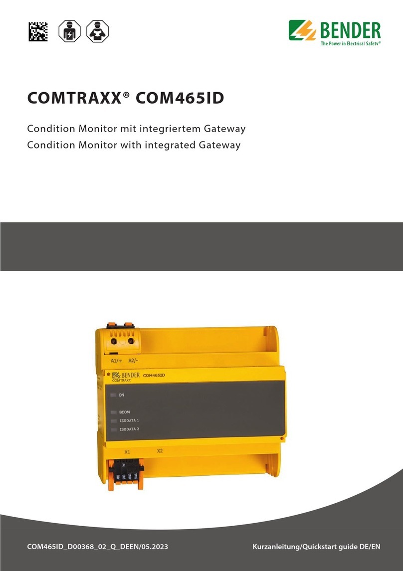
Bender COMTRAXX COM465ID User manual

Bender
Bender COMTRAXX COM463BC User manual
