Bender COMTRAXX COM462RTU User manual

Manual
EN
COM462RTU_D00010_03_M_XXEN/04.2018
COMTRAXX® COM462RTU
BMS-Modbus RTU gateway for the connection
of BMS-capable Bender devices
to the Modbus RTU
Software version: D415 V1.2x

Table of Contents
3
COM462RTU_D00010_03_M_XXEN/04.2018
1. Important information .................................................................................... 7
1.1 How to use this manual ................................................................................. 7
1.2 Technical support: Service and support .................................................. 8
1.2.1 First level support ............................................................................................. 8
1.2.2 Repair service ..................................................................................................... 8
1.2.3 Field service ........................................................................................................ 9
1.3 Training courses ................................................................................................ 9
1.4 Delivery conditions .......................................................................................... 9
1.5 Inspection, transport and storage ........................................................... 10
1.6 Warranty and liability ................................................................................... 10
1.7 Disposal ............................................................................................................ 11
1.8 Quick-start guide ........................................................................................... 11
2. Safety instructions ......................................................................................... 13
2.1 General safety instructions ........................................................................ 13
2.2 Work activities on electrical installations ............................................. 13
2.3 Intended use ................................................................................................... 14
2.4 Address setting and termination ............................................................. 14
3. Product description ....................................................................................... 15
3.1 Scope of delivery ........................................................................................... 15
3.2 Short description ........................................................................................... 15
3.3 Device features .............................................................................................. 15
3.4 Possible applications ................................................................................... 15
3.5 Details about the Modbus RTU ................................................................ 16
4. Installation, connection and commissioning ........................................... 17
4.1 Preliminary considerations ........................................................................ 17
4.2 COM462RTU on the internal BMS bus ................................................... 18

Table of Contents
4COM462RTU_D00010_03_M_XXEN/04.2018
4.3 Installing the device ..................................................................................... 19
4.4 Connecting the device ................................................................................ 20
4.5 Commissioning .............................................................................................. 22
5. Operation and configuration ...................................................................... 23
5.1 Display and operating elements .............................................................. 23
5.1.1 Automatic contrast setting for the display .......................................... 24
5.1.2 Display in standard mode .......................................................................... 24
5.1.3 Display in menu mode ................................................................................ 25
5.2 Factory settings .............................................................................................. 25
5.3 Settings on the device ................................................................................. 26
5.3.1 Operating example: Setting BMS address ............................................ 26
5.4 Display INFO list ............................................................................................. 28
6. Data access using Modbus RTU protocol .................................................. 29
6.1 Exception code ............................................................................................... 29
6.2 Modbus requests ........................................................................................... 30
6.3 Modbus responses ........................................................................................ 30
6.4 Structure of the exception code .............................................................. 31
6.5 Modbus address structure for BMS devices ......................................... 31
7. Modbus process image in the memory of the COM462RTU ................. 33
7.1 Querying data ................................................................................................. 33
7.1.1 Modbus function code ................................................................................ 33
7.1.2 How are the memory areas organised? ................................................ 33
7.2 Memory scheme of the process image ................................................. 35
7.2.1 BMS device address assignment on the Modbus .............................. 35
7.2.2 Memory scheme of an individual BMS device .................................... 36
7.2.3 Device type ...................................................................................................... 38
7.2.4 Timestamp ....................................................................................................... 39
7.2.5 Common alarm and device failure .......................................................... 39
7.2.6 Channels 1 to 32 with analogue and/or digital values .................... 40
7.2.6.1 Float = Floating point value of the BMS channels .................... 40

Table of Contents
5
COM462RTU_D00010_03_M_XXEN/04.2018
7.2.6.2 AT&T = Alarm type and test type (internal/external) .............. 41
7.2.6.3 R&U = Range and unit ......................................................................... 43
7.2.6.4 Channel description ............................................................................ 45
7.2.6.5 Channel 33 to 64 ................................................................................... 46
7.3 Reference data records of the process image .................................... 47
7.3.1 Address assignment of the reference data record ............................ 47
7.3.2 Reference value on channel 1 ................................................................... 48
7.3.3 Reference value on channel 2 ................................................................... 49
7.3.4 Explanation of how to access floating point values ......................... 49
7.4 Channel descriptions for the process image ....................................... 51
7.5 Modbus control commands ...................................................................... 63
8. Technical data ................................................................................................. 67
8.1 Tabular data .................................................................................................... 67
8.2 Dimension diagram ...................................................................................... 69
8.3 Standards, approvals, certifications ........................................................ 69
8.4 Ordering details ............................................................................................. 70
9. Troubleshooting ............................................................................................ 71
9.1 Malfunctions ................................................................................................... 71
9.1.1 What should be checked? .......................................................................... 71
9.1.2 Where to find help? ...................................................................................... 71
INDEX ..................................................................................................................... 73

7
COM462RTU_D00010_03_M_XXEN/04.2018
1. Important information
1.1 How to use this manual
Always keep this manual within easy reach for future reference.
To make it easier for you to understand and revisit certain sections in this man-
ual, we have used symbols to identify important instructions and information.
The meaning of these symbols is explained below:
This manual is intended for qualified personnel working in
electrical engineering and electronics!
This signal word indicates that there is a high risk of danger,
that will result in death or serious injury if not avoided.
This signal word indicates a medium risk of danger that can
lead to death or serious injury, if not avoided.
This signal word indicates a low-level risk that can result in
minor or moderate injury or damage to property if not
avoided.
This symbol denotes information intended to assist the user
in making optimum use of the product.
DANGER
WARNING
CAUTION

Important information
8COM462RTU_D00010_03_M_XXEN/04.2018
This manual has been compiled with great care. It might nevertheless contain
errors and mistakes. Bender cannot accept any liability for injury to persons or
damage to property resulting from errors or mistakes in this manual.
1.2 Technical support: Service and support
For commissioning and troubleshooting Bender offers you:
1.2.1 First level support
Technical support by phone or e-mail for all Bender products
Questions concerning specific customer applications
Commissioning
Troubleshooting
Telephone: +49 6401 807-760*
Fax: +49 6401 807-259
In Germany only: 0700BenderHelp (Tel. and Fax)
E-mail: [email protected]
1.2.2 Repair service
Repair, calibration, update and replacement service for Bender products
Repairing, calibrating, testing and analysing Bender products
Hardware and software update for Bender devices
Delivery of replacement devices in the event of faulty or incorrectly
delivered Bender devices
Extended guarantee for Bender devices, which includes an in-house
repair service or replacement devices at no extra cost
Telephone: +49 6401 807-780** (technical issues)
+49 6401 807-784**, -785** (sales)
Fax: +49 6401 807-789
E-mail: [email protected]

Important information
9
COM462RTU_D00010_03_M_XXEN/04.2018
Please send the devices for repair to the following address:
Bender GmbH, Repair-Service,
Londorfer Straße 65,
35305 Grünberg
1.2.3 Field service
On-site service for all Bender products
Commissioning, parameter setting, maintenance, troubleshooting for
Bender products
Analysis of the electrical installation in the building (power quality test,
EMC test, thermography)
Training courses for customers
Telephone: +49 6401 807-752**, -762 **(technical issues)
+49 6401 807-753** (sales)
Fax: +49 6401 807-759
E-mail: fieldservice@bender-service.de
Internet: www.bender-de.com
*Available from 7.00 a.m. to 8.00 p.m. 365 days a year (CET/UTC+1)
**Mon-Thurs 7.00 a.m. - 8.00 p.m., Fr 7.00 a.m. - 13.00 p.m.
1.3 Training courses
Bender is happy to provide training regarding the use of test equipment.
The dates of training courses and workshops can be found on the Internet at
www.bender-de.com -> Know-how -> Seminars.
1.4 Delivery conditions
Bender sale and delivery conditions apply.

Important information
10 COM462RTU_D00010_03_M_XXEN/04.2018
For software products, the "Softwareklausel zur Überlassung von Standard-
Software als Teil von Lieferungen, Ergänzung und Änderung der Allgemeinen
Lieferbedingungen für Erzeugnisse und Leistungen der Elektroindustrie"
(software clause in respect of the licensing of standard software as part of de-
liveries, modifications and changes to general delivery conditions for prod-
ucts and services in the electrical industry) set out by the ZVEI (Zentralverband
Elektrotechnik- und Elektronikindustrie e.V.) (German Electrical and Electronic
Manufacturers' Association) also applies.
Sale and delivery conditions can be obtained from Bender in printed or elec-
tronic format.
1.5 Inspection, transport and storage
Inspect the dispatch and equipment packaging for damage and compare the
contents of the package with the delivery documents. In the event of damage
in transit, please contact Bender immediately.
The devices must only be stored in areas where they are protected from dust,
damp, and spray and dripping water, and in which the specified storage tem-
peratures can be ensured.
1.6 Warranty and liability
Warranty and liability claims in the event of injury to persons or damage to
property are excluded if they can be attributed to one or more of the follow-
ing causes:
Improper use of the device.
Incorrect mounting, commissioning, operation and maintenance of the
device.
Failure to observe the instructions in this operating manual regarding
transport, commissioning, operation and maintenance of the device.
Unauthorised changes to the device made by parties other than the
manufacturer.
Non-observance of technical data.
Repairs carried out incorrectly and the use of replacement parts or
accessories not approved by the manufacturer.

Important information
11
COM462RTU_D00010_03_M_XXEN/04.2018
Catastrophes caused by external influences and force majeure.
Mounting and installation with device combinations not recom-
mended by the manufacturer.
This operating manual, especially the safety instructions, must be observed by
all personnel working on the device. Furthermore, the rules and regulations
that apply for accident prevention at the place of use must be observed.
1.7 Disposal
Abide by the national regulations and laws governing the disposal of this de-
vice. Ask your supplier if you are not sure how to dispose of the old equip-
ment.
The directive on waste electrical and electronic equipment (WEEE directive)
and the directive on the restriction of certain hazardous substances in electri-
cal and electronic equipment (RoHS directive) apply in the European Commu-
nity. In Germany, these policies are implemented through the "Electrical and
Electronic Equipment Act" (ElektroG). According to this, the following applies:
Electrical and electronic equipment are not part of household waste.
Batteries and accumulators are not part of household waste and must
be disposed of in accordance with the regulations.
Old electrical and electronic equipment from users other than private
households which was introduced to the market after 13th August 2005
must be taken back by the manufacturer and disposed of properly.
For more information on the disposal of Bender devices, refer to our
homepage at www.bender-de.com -> Service & support.
1.8 Quick-start guide
Connection of the COM462RTU
If you are familiar with the installation and connection of electrical devices,
particularly with Modbus RTU, you can start right away with the wiring dia-
gram on page 20.
It may also be helpful to refer to the block diagrams representing an applica-
tion example with an internal BMS bus (BMS=Bender measuring device inter-
face) on page 18.

13
COM462RTU_D00010_03_M_XXEN/04.2018
2. Safety instructions
2.1 General safety instructions
Part of the device documentation in addition to this manual is the enclosed "
Safety instructions for Bender products".
2.2 Work activities on electrical installations
If the device is used outside the Federal Republic of Germany, the applicable
local standards and regulations must be complied with. The European stand-
ard EN 50110 can be used as a guide.
Only qualified personnel are permitted to carry out the
work necessary to install, commission and run a device or
system.
Risk of electrocution due to electric shock!
Touching live parts of the system carries the risk of:
An electric shock
Damage to the electrical installation
Destruction of the device
Before installing and connecting the device, make sure
that the installation has been de-energised. Observe the
rules for working on electrical installations.
DANGER

Safety instructions
14 COM462RTU_D00010_03_M_XXEN/04.2018
2.3 Intended use
The BMS-Modbus RTU gateway COM462RTU connects the serial Bender BMS
bus to the serial Modbus RTU. The gateway converts alarms, measured values
and statuses from the BMS bus to Modbus RTU. Control commands can be
converted from Modbus RTU to BMS bus.
This allows connection to Modbus networks. The gateway is operated on the
internal BMS bus.
2.4 Address setting and termination
In order to ensure proper functioning of the BMS-Modbus RTU gateway
COM462RTU, correct address assignment and termination of the BMS bus and
the Modbus RTU is of utmost importance.
Ensure correct address setting and termination of the COM462RTU. For details
refer to "Commissioning" on page 22.
Interface on the Modbus RTU side
Interface on the BMS side:
COM462RTU can be operated as master or slave.
Assigning addresses that are already used by existing devices
in the BMS or Modbus RTU networks concerned may cause
serious malfunctions.
The COM462RTU is always operated as slave on the Modbus
RTU side. Therefore, the COM462RTU and its Modbus RTU
has to be communicated to the Modbus RTU master.
CAUTION

15
COM462RTU_D00010_03_M_XXEN/04.2018
3. Product description
3.1 Scope of delivery
You will receive:
the COM462RTU
an operating manual
3.2 Short description
The BMS-Modbus RTU gateway COM462RTU contains a Modbus RTU slave
that converts BMS data for a Modbus master.
A setting menu makes it possible to configure the COM462RTU using the set-
ting menu (see "Commissioning" on page 22).
3.3 Device features
Setting of address data for the BMS bus and Modbus RTU and date and
time setting using the internal operating menu.
Time synchronisation for all BMS bus devices
Operation on the internal BMS bus
Modbus RTU data access to the internal BMS bus, max. 150 BMS
devices
Commands can be sent from an external application (e.g. visualisation
software) to BMS devices and measured values read.
3.4 Possible applications
The use of professional visualisation programs by converting BMS data
to Modbus RTU protocols.
Observing and analysing Bender products that support communica-
tion, such as RCMS, EDS and MEDICS® systems.

Product description
16 COM462RTU_D00010_03_M_XXEN/04.2018
3.5 Details about the Modbus RTU
The Modbus RTU (Remote Terminal Unit) field bus has been specified by Mod-
icon, a company under the Schneider Automation brand and made available
to the market license-free.
Modbus uses the serial hardware interface RS-485 and communicates via a
two-wire, twisted copper wire. A transmission rate of 19200 baud is standard.
Key data:
Master-slave communication
Up to 32 bus devices per network, or up to 247 bus devices (with
repeater)
Baud rate between 1200 and 57600 bit/s
Diagnostics mechanisms

17
COM462RTU_D00010_03_M_XXEN/04.2018
4. Installation, connection and commissioning
4.1 Preliminary considerations
1. Have all the questions as regards the installation been answered by the
technician responsible for the installation?
2. The device is operated on the internal bus. Is the BMS address to be set
known?
If, apart from the COM462RTU, an alarm indicator and test combination
MK800 is connected to the internal bus, the COM462RTU must not
have the address 1 (master).
You will find more detailed information on the BMS topic, in particular
about the wiring of bus devices, in the separate document "BMS bus".
Only qualified personnel are permitted to carry out the
work necessary to install, commission and run a device or
system.
Risk of electrocution due to electric shock!
Touching live parts of the system carries the risk of:
An electric shock
Damage to the electrical installation
Destruction of the device
Before installing and connecting the device, make sure
that the installation has been de-energised. Observe the
rules for working on electrical installations.
If you are familiar with the configuration of Modbus RTU
networks, you can carry out the connection of the
COM462RTU by yourself. Otherwise please contact your
EDP administrator!
DANGER

Installation, connection and commissioning
18 COM462RTU_D00010_03_M_XXEN/04.2018
You can download the document from the download area of the web-
site www.bender-de.com.
3. Is the Modbus RTU address to be set known?
4.2 COM462RTU on the internal BMS bus
Bender systems such as EDS46x/49x, RCMS46x/49x and MEDICS communi-
cate with each other via the Bender measuring device interface BMS.
The BMS-Modbus RTU gateway COM462RTU provides the coupling between
the BMS bus and Modbus RTU networks. The following block diagram illus-
trates the operation of the gateway in an internal BMS bus.
Fig. 4.1: Block diagram of a coupling between an internal BMS bus
and Modbus RTU
COM462RTU
D+ D- D- D-D+ D+
D-D+
Modbus RTU

Installation, connection and commissioning
19
COM462RTU_D00010_03_M_XXEN/04.2018
4.3 Installing the device
Possible methods of mounting:
DIN rail mounting
Screw mounting with 2 x M4 (dimension diagram on page 69)
Internal and external BMS bus
The majority of Bender devices communicate via the internal
BMS bus.
Individual devices, such as MK800, TM800 or Bender panels
can communicate via both the internal BMS bus (BMS i) and
the external BMS bus (BMS e).
The BMS-Modbus RTU gateway COM462RTU can only
communicate via the internal BMS bus (BMS i).
When installing the device, please take into consideration
that the device is only to be used in locations that are
protected from unauthorised entry! This can be installation
in a switch cabinet, for example.
WARNING

Installation, connection and commissioning
20 COM462RTU_D00010_03_M_XXEN/04.2018
4.4 Connecting the device
For UL applications, the following is to be observed:
– Supply voltage Us: see nameplate and ordering details
– Maximum ambient temperature: 55°C
– For use in pollution degree 2 environments
– Use 60/70°C copper lines only
– Tightening torque for terminals: 0.5…0.6 Nm
Connect the terminals and sockets on the COM462RTU according to the wir-
ing diagram.
A1 A2
AB
IN3 IN4
GND
3/4 BMB
AMB
IN1 IN2
GND
1/2 14
11
A2
A1
6 A 6 A
US
RMB
(AMB, BMB)
BMS-Bus
RS-485
Modbus RTU
RS-485
AMB BMB
ALARM
COM
ON MENU
INFO
ESC
Other manuals for COMTRAXX COM462RTU
1
Table of contents
Other Bender Gateway manuals
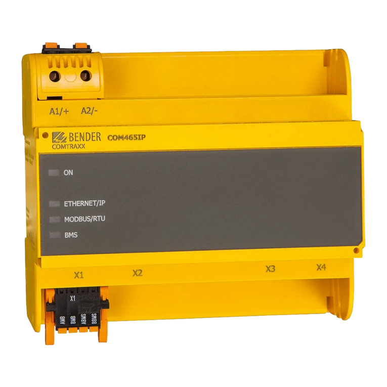
Bender
Bender COM465IP User manual
Bender
Bender COMTRAXX COM463BC User manual
Bender
Bender COM461MT User manual
Bender
Bender COMTRAXX COM465ID User manual

Bender
Bender COMTRAXX COM462RTU User manual

Bender
Bender COMTRAXX COM460IP User manual

Bender
Bender COMTRAXX COM463BC User manual

Bender
Bender COMTRAXX COM463BC User manual

Bender
Bender COM465IP User manual

Bender
Bender COMTRAXX COM463BC User manual


