Bender IR5002 User manual
Insulation monitoring device for
IT DC systems 350 ... 800 V
IR5002
Operating Manual
TGH 1360E
Edition 04/2008
Quality System
Certified
ISO 9001
MiniMax
IR5002
ALARM L- ALARM L+
ENTER
kΩ
MONITOR
****** BENDER ******
A - ISOMETER IR5002
Version 1.2 / 5.96
ENTER

Dipl.-Ing. W. Bender
GmbH+CoKG
Londorfer Str. 65
D-35305 Gr nberg
Postfach 1161
D-35301 Gr nberg
Tel. 06401/807-0
Fax 06401/807-259
E-Mail [email protected]
IR5002
Operating manual
TGH 1360EEdition 04/2005
Edited by
Dipl.-Ing. W. BENDER GmbH+CoKG
This manual may not be copied, in whole
or part, without written consent of BENDER.
All rights reserved.
Right to modifications reserved._Mac_PM6.5

3
TGH 1360E
1 General .................................................................................. 4
About the IR5002 ........................................................................... 4
IT System....................................................................................... 4
Underlying standards ..................................................................... 4
The concept of IR5002................................................................... 5
Coupling device AG5002 ............................................................... 5
2 Safety information .................................................................. 6
Intended use .................................................................................. 6
Personnel....................................................................................... 6
Copyright........................................................................................ 6
Warranty and liability...................................................................... 7
Explanation of symbols and warnings............................................ 7
Hazards when handling the system ............................................... 7
Inspection, transport and storage .................................................. 8
Warranty statement........................................................................ 8
3 Principle of operation ............................................................. 9
Symmetrical and asymmetrical insulation faults .......................... 10
4 Product description .............................................................. 11
Mechanical design ........................................................................11
Dimension diagrams .................................................................... 12
Wiring diagram............................................................................. 14
Legend to wiring diagram............................................................. 15
Terminal strips.............................................................................. 16
5 Setting and operation .......................................................... 17
Function keys............................................................................... 17
Welcome screen .......................................................................... 17
Main screen ................................................................................. 17
Menus .......................................................................................... 18
The individual menus ................................................................... 19
Setting the response values......................................................... 19
Time response ............................................................................. 19
Indication of the time response .................................................... 21
Operating principle of the alarm relays ........................................ 21
N/O or N/C operation ................................................................... 22
Setting the threshold of the voltage ............................................. 22
Setting the serial interface ........................................................... 23
Adjusting digital input 1 ................................................................ 23
Temperature display..................................................................... 24
Setting date and time ................................................................... 24
Software version .......................................................................... 25
Factory settings............................................................................ 25
6 Wiring and commissioning ................................................... 26
Error messages............................................................................ 29
System errors, CRITICAL ERRORS ............................................ 30
Indication of asymmetrical faults.................................................. 31
Data output .................................................................................. 32
7 Technical Data...................................................................... 33
Analog output IR5002 .................................................................. 35
Contents

4
TGH 1360E
About the IR5002
1 General
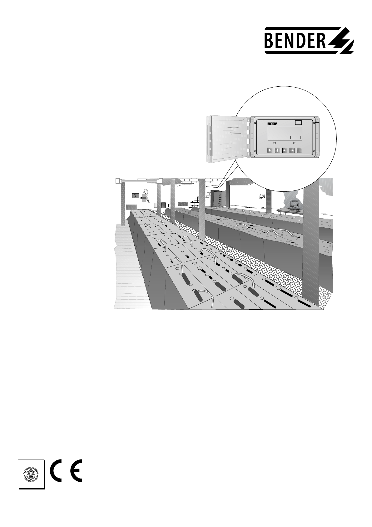
With the insulation monitoring device IR5002, BENDER offers a special
equipment for continuous monitoring of the insulation resistance of IT DC
systems to earth. The device is intended to indicate when the value falls below a
preset response value.
The IR5002 is suitable for IT DC systems involving:
• systems with low insulation resistance and high nominal voltages
• systems with water-cooled components
• heating systems with ionizing air
• smelting plants
• extended systems
Special features of the IR5002 are:
• voltage range of the system to be monitored:
DC 350 ... 800 V
• 3-voltmeter method for fast detection of symmetrical and asymmetrical
insulation faults
• wide response range: 5Ω ... 100 kΩ
• integrated voltage monitoring
• two serial interfaces: RS232 and RS485
• linear analog output 0...20 mA
• three different alarm relays for earth fault at L+, earth fault at L- and
system faults
• large LC display
• control via microcontroller
• real-time clock
• menu-driven operating and setting
• robust enclosure for surface mounting
If increased availability of power supply is concerned, the IT system, i.e. the
unearthed system, is the right choice. In contrast to the earthed system, the first
insulation fault does not lead to a disconnection. Combined with a well-chosen
insulation monitoring device, insulation faults and deteriorations are recognized
early, possibly when developing. Hence, increased availability of power supply
in an IT system stands and falls with the well-chosen insulation monitoring
device.
Maintaining a good insulation condition is decisive for reliable power supply.
Therefore the relevant standards demand that the first fault is to be cleared as
soon as possible.
IEC 60364-4-41 Punkt 413.1.5.4 (Note):
It is recommended that the first fault should be eliminated with the shortest
practical delay.
The A-ISOMETER ® IR5002 complies with the requirements of IEC 61557-8.
The internal resistance has been adapted to the special applications for systems
with low insulation resistance values.
The standard deals with constructional and measuring parameters as well as the
test procedures, and the safety aspects of the insulation monitoring devices in
IT systems, including the use in IT AC systems, IT DC systems and IT DC
systems with galvanically connected DC circuits.
Underlying
standards
IT System

5
TGH 1360E
General
IR5002 works according to a passive 3-voltmeter method. Different voltages are
measured within the system to be monitored. Comparative measurements of the
internal resistor network are carried out in order to determine the correct
insulation resistance of the system.
For calculation of the insulation resistance, the measured analog voltages are
digitilized by a 22-bit AD converter which is connected to the microcontroller
via a serial bus.
The detection, processing, analysis and output of the measured values are
controlled by a microcontroller which allows the setting of different parameters.
The measured values can be transmitted to peripheral devices, e.g. computers or
PLC via serial interfaces.
The device parameter settings are stored in a non-volatile EEPROM. The values
of the insulation resistance and the time when the measurements are carried out
are indicated by the internal real-time clock.
The measuring circuit is isolated from the output circuits (relays, interfaces).
That provides adequate safety of the IR5002 and the connected peripheral
devices.
IR5002 can be used as an independent device or in combination with the
coupling device AG5002. If response values below 1000 Ω are to be set, the use
of a coupling device AG5002 will be necessary. IR5002 recognizes automatically
if a coupling device has been connected.
Coupling device
AG5002
The concept of
IR5002

6
TGH 1360E
2 Safety information
IR5002 is intended exclusively for measuring and evaluating the
insulation resistance in IT DC systems of 350 V to 800 V.
Any other use, or any use which goes beyond the foregoing, is deemed to be use
other than for the intended purpose. The BENDER companies shall not be
liable for any losses or damage arising therefrom.
The basic requisite for handling the IR5002 in accordance with safety
requirements, and for it to operate without faults, is a knowledge of the funda-
mental safety information and the safety regulations.
This manual contains important information needed in order to operate the
IR5002 in accordance with safety requirements. This manual, and
in particular the safety information, must be noted by all persons who work
with the IR5002.
In addition, it is essential to comply with the rules and regulations on accident
prevention which are valid for the place of use.
Only appropriately qualified personnel may work on the IR5002. "Qualified" means
that such personnel are familiar with the installation, commissioning and operation
of the product and that they have undergone training or instruction which is
appropriate to the activity.
The personnel must have read and understood the safety chapter and the warning
information in this operating manual.
The copyright to this operating manual shall remain with the BENDER
Companies. The operating manual is solely intended for the operator and his
personnel. It contains regulations and information which must not be
reproduced, disseminated or otherwise divulged, either in whole or in part.
Contraventions may entail criminal prosecution.
Intended use
Copyright
Warranty and
liability
• use of the IR5002 other than for the intended purpose
• incorrect assembly or installation, commissioning, operation and
maintenance of the IR5002
• failure to comply with the information in the operating instructions
regarding transport, storage, assembly or installation, commissioning,
operation and maintenance of the IR5002
• unauthorized structural modifications to the IR5002
• failure to comply with the technical data
• improperly executed repairs, and the use of spare parts or accessories
which are not recommended by the manufacturer
• cases of disaster and force majeure
normal control, e.g. acts of God
Personnel
As a basic principle, our "General Conditions of Sale and Delivery" shall apply. At
the latest, these shall be available to the operator when the contract is concluded.
Warranty and liability claims in cases of damage to persons and property shall be
excluded if they are attributable to one or more of the following causes:

7
TGH 1360E
Safety information
The following designations and signs are used for hazards and warnings in
Bender documentation.
This symbol means an immediate threat of danger to the life and health of
human beings.
Failure to comply with these warnings means that death, serious physical injury
or substantial damage to property will ensue if the relevant precautions are not
taken.
This symbol means a possible threat of danger to the life and health of human
beings.
Failure to comply with these warnings means that death, serious physical injury
or substantial damage to property may ensue if the relevant precautions are not
taken.
This symbol means a possible dangerous situation.
Failure to comply with these warnings means that slight physical injury or
damage to property may ensue if the relevant precautions are not taken.
This symbol gives important information about the correct handling of the
IR5002.
Failure to comply with this information can result in faults on the IR5002 or in
its environment.
Where you see this symbol, you will find application tips and other particularly
useful information.
This information will help you to make optimal use of the IR5002.
Explanations of
symbols and
warnings
The IR5002 is constructed according to the state-of-the-art and the recognized safety
engineering rules. Nevertheless, when it is being used, hazards may occur to the life
and limb of the user or of third parties, or there may be adverse effects on the IR5002
or on other valuable property. The IR5002 must only be used:
• for the purpose for which it is intended
• when it is in perfect technical condition as far as safety is concerned
Impermissible modifications and the use of spare parts and additional devices which
are not sold or recommended by the manufacturer of the devices may cause fire,
electric shocks and injury.
Hazards when
handling the
system
Danger !
Warning
Attention
Make sure that the operating voltage is correct!
Unauthorized persons must not have access to or contact with the IR5002.
Warning signs must always be easily legible. Damaged or illegible signs must be
replaced immediately.
Check the dispatch packaging and the equipment packaging for damage, and
compare the contents of the package with the delivery documents. In the event
of damage during transport, please notify BENDER immediately.
The IR5002 must only be stored in rooms where it is protected against dust and
moisture, and spraying or dripping water, and where the indicated storage
temperatures are maintained.
Inspection,
transport and
storage

8
TGH 1360E
Safety information
In respect of the IR5002, BENDER provides a warranty of fault-free execution
and perfect material quality under normal operation and maintenance
conditions, for a period of 24 months from the date of delivery. This warranty
does not extend to all accessories and consumable components.
For warranty the device must be returned, prepaid, to the nearest authorized
Bender service representative.
The warranty shall only be valid for the first purchaser, and shall not extend to
products or individual parts thereof which have not been correctly used, or
which have undergone modifications. Any warranty shall lapse if the IR5002 is
used other than for the intended purpose.
The warranty obligation is limited to the repair or the exchange of a product
which has been sent to BENDER within the warranty period. The qualifying
conditions are that BENDER shall recognize the product as being faulty, and
that the fault cannot be attributed to improper handling or modification of the
device, nor to abnormal operating conditions.
Any warranty obligation shall lapse if repairs are undertaken on the IR5002 by
persons who are not authorized by BENDER.
The foregoing warranty provisions are valid exclusively, and instead of all other
contractual or legal warranty obligations, including (but not restricted to) the
legal warranty of marketability, suitability for use and expediency for a specified
use.
BENDER shall not assume any liability for direct or indirect concomitant or
subsequent damage, regardless of whether these are attributable to legal, illegal
or other actions.
This statement of warranty shall only be valid in conjunction with the delivery
note from BENDER company.
Warranty
statement
9
TGH 1360E
3 Principle of operation
IR5002 uses the measuring principle "3-Voltmeter-Method". Asymmetrical as well
as symmetrical insulation faults in IT DC systems can be detected according to
this measuring principle. In combination with the microcontroller a fast, safe
and exact measurement and evaluation can be realized.
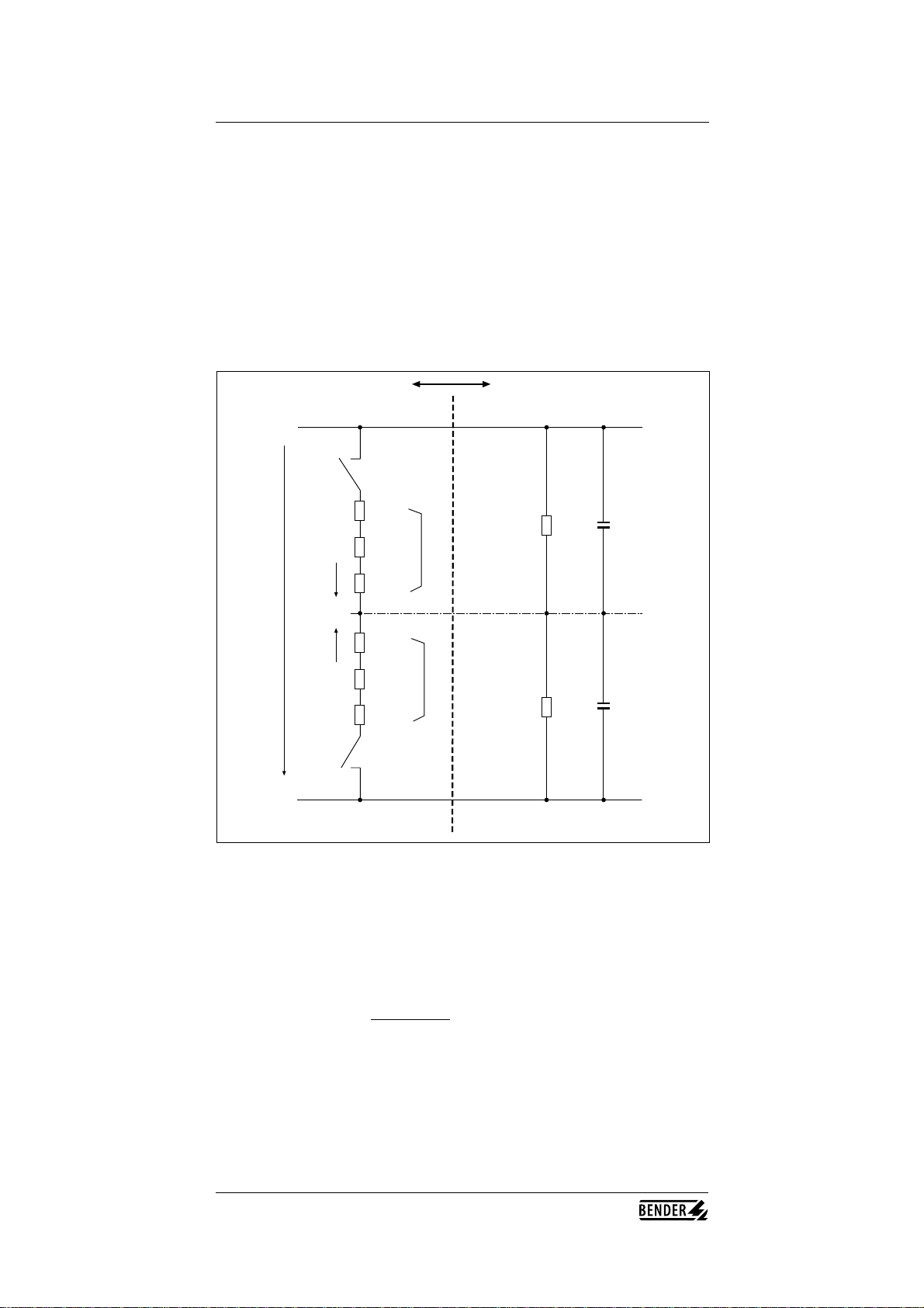
In some respect, the measuring time is dependent on the system leakage
capacitances CE+ and CE- (illustrated below). The capacitances are always
recharged when the coupling switches are closed resp. opened.
internal coupling monitored system
L+
PE
L-
S1
R1.1
Rm1
S2
R2.1
Rm2
RF-
RF+ CE+
CE-
R1
R2
UN
U1
U2
The time delay prevents false trippings during recharging:
• S1 closed, S2 opened measuring of the voltage U1 at Rm1
• S1 opened, S2 closed measuring of the voltage U2 at Rm2
• S1 and S2 closed measuring of the voltage UN
UN= (U1+U2) x R1+R2
Rm1+Rm2

10
TGH 1360E
The insulation resistances RF+ and RF- can be calculated according to the
following equations:
• for symmetrical coupling, i.e R1=R2 and Rm1=Rm2
Principle of operation
(UN x Rm1 - (U1+U2) x R2)
RE+ = U2
• for asymmetrical coupling, i.e. relation AK+ / AK- = 2:1
(UN x Rm2 - (U1+U2) x R1)
RE- = U1
RE+ = (UN x Rm1 x (UN x Rm2 - R2 x (U1 + U2)))
(U2 x (UN x Rm1 - U1 x R2))
RE- = (UN x Rm1 x (UN x Rm2 - R2 x (U1 + U2)))
(U1 x (UN x Rm2 - U2 x R2))
Condition: R1 = 2 x R2
Rm1 = 2 x Rm2
These calculations of the insulation resistances are done by the integrated
microcontroller. The results are indicated on the display.
Symmetrical and
asymmetrical
insulation faults
The measuring values are determined by the device with a passive measuring
principle. This entails some specialities regarding the measured insulation values.
If the relation between the single insulation values RF+ and RF- is high
(asymmetrical faults) the accuracy of the higher value is less than the accuracy of
the lower value, because the measuring voltage drop for an insulation fault is
gathered at the opposite side of the coupling network. That means that the
main measuring voltage for the higher value decreases with the dropping of the
lower insulation value. In the reverse case the measuring voltage of the lower
value increases with the dropping of this value. Because of this, the lower value
is measured with the highest accuracy.
In practice, this effect may entail a little change of the higher value in display
when the lower value increases or decreases.
The accuracy of both values is identical if the insulation values are symmetrical.

11
TGH 1360E
4 Product description
Mechanical designIR5002 is mounted in a 19"-inch plastic casing with a lockable transparent cover.
The casing is equipped with two separate terminal boxes. The upper terminal
box contains terminals for the coupling to the system to be monitored as well as
to the optional coupling device AG5002. The lower terminal box contains
terminals for PE coupling, supply voltage, contacts of the alarm relay, serial
interfaces, temperature sensor input, digital inputs, and analog output.
IR5002
ALARM L- ALARM L+
ENTER
kΩ
MONITOR
****** BENDER ******
A - ISOMETER IR5002
Version 1.2 / 5.96
ENTER
RS232
Isolate elsewhere
before opening
Vorsicht Spannung
Attention
Danger
Isolate elsewhere
before opening
Vorsicht Spannung
Attention
Danger

12
TGH 1360E
side view (right)
Product description
top view
General dimensions according to DIN 7168, dimensions in mm
147
327
71
277
203,5
4,2
100
100 80
227
237
277
front view
Dimension
diagrams

13
TGH 1360E
Product description
Dimensions coupling device AG5002
130
143
Ø 6,5
260
302
22
80
103
14
TGH 1360E
Product description
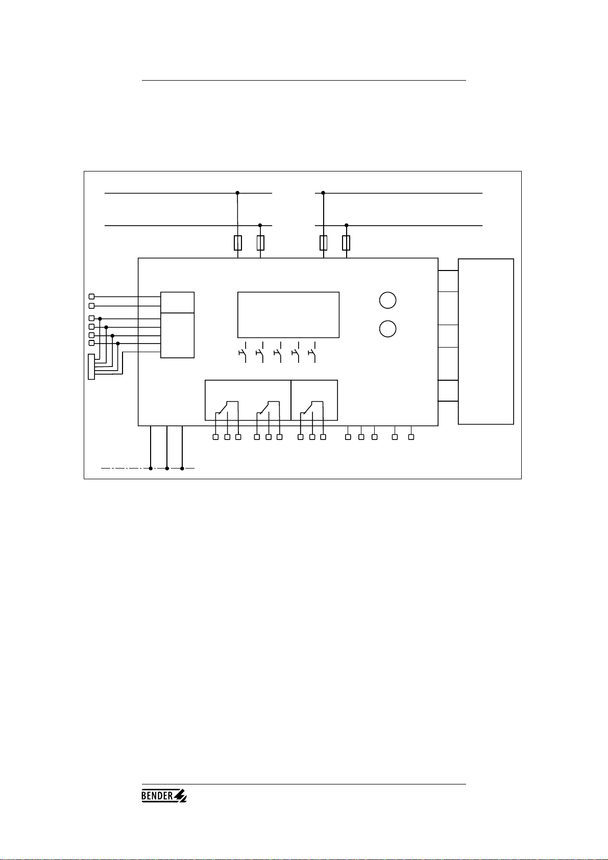
Wiring diagram
monitored system supply voltage
UN = DC 350 - 800 V US = DC 110 V /AC 100 - 240 V
P1
H1
H2
RS485
RS232
S1 S2 S3 S4 S5
Coupling
device
AG5002
AK1/L+
AK1/L-
AK1/U+
AK1/U-
T1
T2
A
B
RxD
TxD
SGND
RTS
CTS
Sub-D
K1 K2 K3
PE PE2 S
PE
E1 E2 EG M+ M-
external
digital
input
optional:
analog
output
0 ... 20 mA
L+ L- L1/L+ N/L-
IR5002

15
TGH 1360E
Product description
Designation Terminal Explanation
designation
P1 LC display, 4 lines á 20 characters
H1 alarm LED red, alarm L+
H2 alarm LED yellow, alarm L-
K1 11,12,11,14 alarm relay alarm L+, 1 change-over contact
K2 21,22,21,24 alarm relay alarm L-, 1change-over contact
K3 31,32,31,34 alarm relay system fault, 1 change-over contact
S1 UP-Taste
S2 DOWN-key
S3 RIGHT-key
S4 LEFT-key
S5 ENTER-key
E1 E1 digital input 1, measurement suppression
E2 E2 digital input 2, (without function at the
moment)
EG EG earth terminal of the digital inputs 1 and 2
L+ L+ system coupling L+
L- L- system coupling L-
AK1/L+ AK1/L+ output L+ of coupling device AG5002
AK1/L- AK1/L- outputg L- of coupling device AG5002
AK1/U+ AK1/U+ input U+ of coupling device AG5002
AK1/U- AK1/U- input U- of coupling device AG5002
T1 T1 positive input temperature measuring of
coupling device AG5002
T2 T2 negative input temperature measuring of
coupling device AG5002
PE PE coupling PE (earth)
PE2 PE2 control earth (connection monitoring)
S PE connection for cable shielding
A A output A RS485 interface
B B output B RS485 interface
M+ M+ analog output + (0...20 mA, linear)
M- M- analog output - (0...20 mA, linear)
RxD, TxD RxD, TxD output RS232 interface on the terminal strip
SGND SGND and on 9-pole Sub-D connector (f)
RTS, CTS RTS, CTS
Legend to wiring
diagram
16
TGH 1360E
Product description
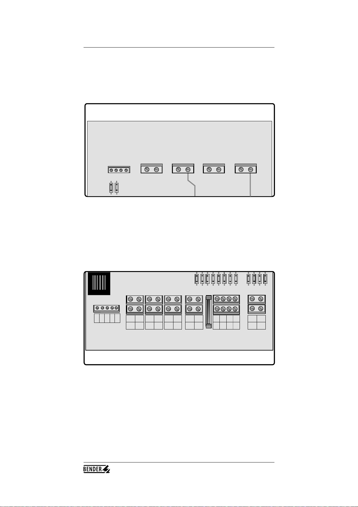
Terminal strips IR5002 is equipped with two separate terminal boxes. The cables are led into the
terminal boxes using screwed cable glands (PG9 and PG11).
Upper terminal box
X1 X2 X3 X4 X5
AK/U+
AK/U-
PE
L+
L-
AK/L+
AK/L-
To external
Coupling
The upper terminal box is exclusively used for the coupling of the measuring
circuit to the system to be monitored and the connection to the optional
coupling device AG5002.
Lower terminal box
X12 X13 X14 X16X15 X17 X18
X19
X10
X11
L1/l+
N/L-
PE
PE
PE2
12
11
14
11
22
21
24
21
32
31
34
31
E1
EG
E2
EG
RTS
T1
M+
T2
M-
RxD TxD
PEBA
GND
PE
SUPPLY
ALARM L+
ALARM L-
AL SYSTEM-
External
Inputs
RS232
RS485
Tem p.
Input
Analogue
Output
The lower terminal box is equipped with the strip terminals X10...X19. These
terminals are used to connect the supply voltage, PE connections as well as all
inputs and outputs.
17
TGH 1360E
5 Setting and operation
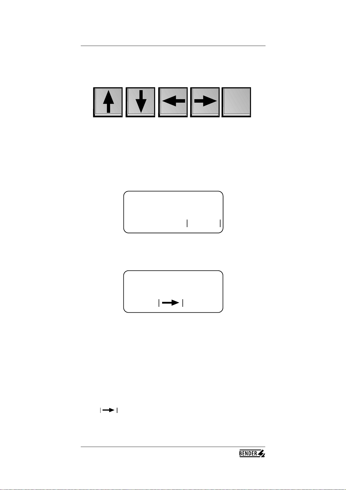
Operation as well as all the settings are carried out by means of the software
using 5 function keys.
UP-key DOWN-key LEFT-key RIGHT-key ENTER-key
When operating under normal conditions, the main screen displays the currently
applicable measuring values. For changing parameters or settings, the main
menue has to be selected.
Once the power supply is switched on, the welcome screen appears displaying
the manufacturer's name (BENDER), the device type, and the firmware version.
ENTER
The welcome screen is displayed for about 5 seconds and then automatically
changes to the main screen. If the ENTER-key is activated within this time, the
main screen will be displayed immediately.
The picture above shows a main screen typical for IR5002 during operation.
U- = 564 V The currently applicable measuring value of the negative pole-
to-earth voltage is 564 V
UN = 620 V The current measured value of the nominal system voltage
is 620 V
RF- = 100kΩThe negative pole-to-earth insulation resistance is 100 kΩ
(calculated value)
RF+ = 10 kΩThe positive pole-to-earth insulation resistance is 10 kΩ
(calculated value)
AL- = 100 kΩThe pre-set response value for the negative fault is 100 kΩ
AL+ = 10 kΩThe pre-set response value for the positive fault is 10 kΩ
Menue: Press the RIGHT-key to change to the respective menu
08:37 System time of the IR5002 (real time clock)
Function keys
Welcome screen
Main screen
*******BENDER*******
*A-ISOMETER IR5002*
*VERSION L2.0/05.96*
ENTER
U- = 564 V UN = 620 V
RF- = 100kΩRF+ = 10kΩ
AL- = 100kΩAL+ = 10kΩ
Menue: 08:37

18
TGH 1360E
Setting and operation
The following picture shows a main menu indicating that the measurement
suppression has been activated. Measurement suppression can be activated or
deactivated by digital input 1. IR5002 is isolated from the system to be
monitored during measurement suppression.
**** MEASURING ****
*** SUPPRESSION ***
****** ACTIVE ******
Menue: 08:37
IR5002 offers 10 different menus for setting and operation. Pushing the RIGHT-
key from the main screen opens the screen with the menu selection.
Of course, not all the menus can be presented within one four-line LC display.
You can choose between 3 menus by scrolling the display via the UP and
DOWN keys. The other menus can be selected by scrolling the DOWN key.
In order to activate the desired menu, scroll the UP and DOWN keys and
position the cursor on the respective digit. Then activate the menu by pushing
the ENTER-key.
All menus are displayed in the following picture:
1. MAIN SCREEN
2. RESPONSE VALUES
3. ALARM TIMING
ENTER
Menus
1. MAIN SCREEN
2. RESPONSE VALUES
3. ALARM TIMING
4. RELAY MODE
5. ALARM SYST. VOLT.
6. SERIAL INTERFACE
7. ENABLE MEASUREM.
8. TEMPERATURE
9. SET CLOCK
10.ABOUT
ENTER

19
TGH 1360E
Setting and operation
The individual
menus
After positioning the cursor on menu 1 MAIN SCREEN by means of the UP
and DOWN keys and activating the ENTER-key, the already familiar screen
appears.
In menu 2 RESPONSE VALUES it is possible to set the response values for
positive and negative faults separately.
By positioning the cursor on 1 MAIN SCREEN, the IR5002 links to the MAIN
SCREEN for setting the response values. Selecting 2 (AL+) allows for setting the
response value for positive faults.
After selecting 2 AL+ by activating the ENTER-key, use the LEFT and RIGHT-
key to select the respective digit you are going to change. Select the appropriate
value by scrolling the UP and DOWN key. The digit can be changed in 1-unit
steps. If you position the cursor on k of the dimension kΩ, for example, you
can change the dimension from Ω into kΩ or vice versa by scrolling the UP and
DOWN key.
Confirming with ENTER after finishing the modifications returns you to the
previous screen. In the same way, the response value for the negative fault AL-
can be changed.
Positioning the cursor onto 1 MAIN SCREEN and confirming with ENTER
opens the MAIN MENU.
From the main menu select the submenu 3 ALARM TIMING for setting the
delay time.
In the submenu 2 DELAY TIME, it is possible to set a delay time between 0 and
100 seconds for the alarm relays. To open this sub menu position the cursor
onto 2 and confirm with ENTER.
Time response
Setting the
response values
1. MAIN MENU
2. DELAY-TIME: 10s
3. WINDOW-TIME: 50s
ENTER
1. MAIN MENU
2. AL+ = 100kΩ
3. AL- = 100kΩENTER
1. MAIN MENU
2. AL+ = 100kΩ
3. AL- = 100kΩENTER
20
TGH 1360E
Setting and operation
As shown in the picture above, the cursor is now positioned before the time
display (10s). Now choose the new value by scrolling the UP and DOWN keys.
This is possible in five-second steps. Confirming with ENTER accepts the
selected value and returns you to the sub menus 1, 2 or 3. Proceed in the same
way if you are going to set the value for WINDOW TIME. Here you can
choose the value in 10-seconds steps between 10 and 300 seconds.
DELAY TIME and WINDOW TIME are dependent on each other. Accordingly
some explanations:
If an insulation fault occurs the DELAY TIME starts running and stops when
the pre-set delay time is reached unless the insulation fault has been cleared. The
counter stops running as soon as the insulation fault is cleared within the
running DELAY TIME.
The WINDOW TIME also starts running when an insulation fault is detected.
Yet, unlike the DELAY TIME, the WINDOW TIME will not be interrupted if
the insulation fault is cleared within this period.
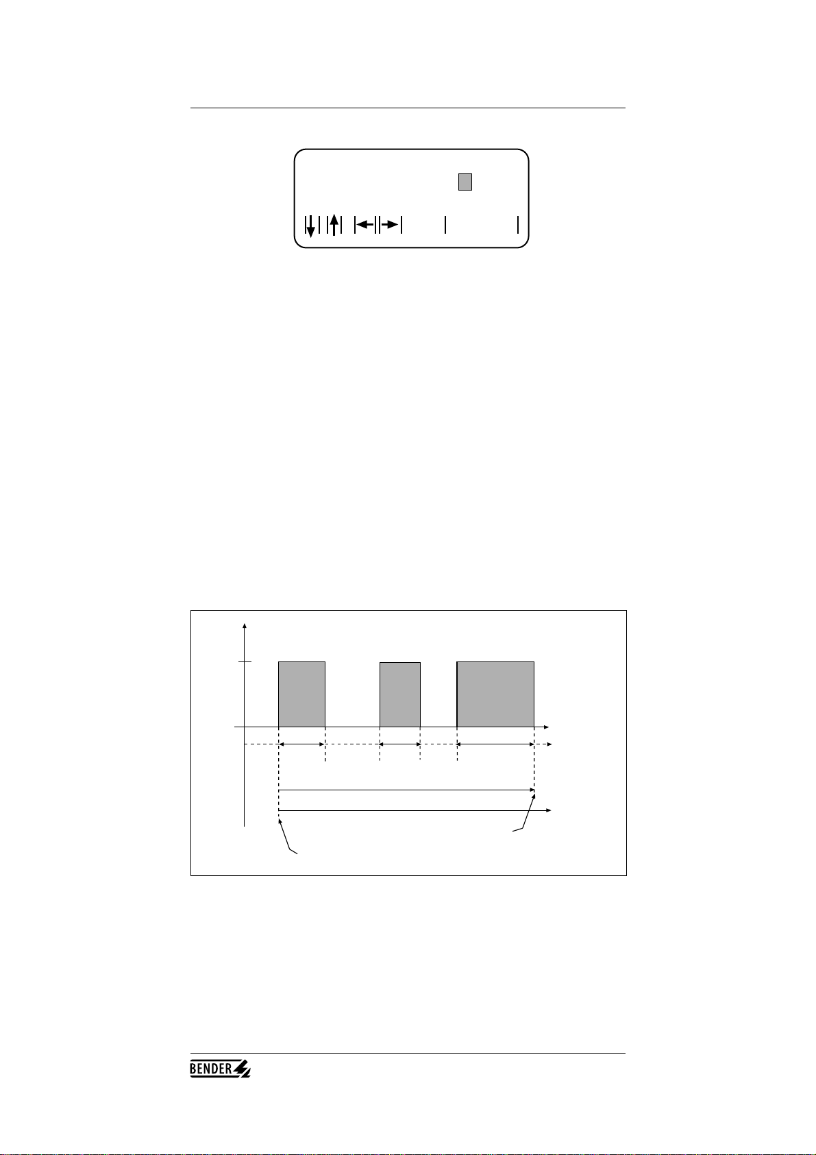
The following diagram shows the correlation between fault detection and the
different times.
Insulation
fault
Insulation
OK t
delay-time
t1 t2 t3
t4
window-time
Alarm is activated
Beginning of delay-time and window-time
After detecting the insulation fault the DELAY TIME and WINDOW TIME
start running. The pre-condition for the activation of the alarm relay is:
Activation if:
(t1 + t2 + t3) > delay-time .AND. (t4 < window-time)
Important:
The pre-set value for the WINDOW TIME has always to be greater than the pre-
set DELAY TIME.
1. MAIN MENU
2. DELAY-TIME: 10s
3. WINDOW-TIME: 50s
ENTER
Table of contents
Other Bender Industrial Equipment manuals


