Bender AGH520S User manual

Handbuch/Manual DE/ENAGH520S_D00073_04_M_DEEN/01.2021
AGH520S
カップリングデバイス / Coupling device

General instructions
Using the manual
This manual is intended for qualified per-
sonnel working in electrical engineering
and electronics! Part of the device docu-
mentation in addition to this manual is the
enclosed „ Safety instructions for Bender
products“.
Furthermore, the rules and regulations
that apply for accident prevention at the
place of use must be observed.
Read the operating manual before starting
to install, connect and commission the de-
vice. „Keep the manual with in easy reach
for future references.“
Marking of importent instructions and
informations
IDanger! indicates a high level of risk that will
lead to death or serious injury.
IWarning!indicates a medium level of risk that
clead to death or serious injury.
ICaution! indicates a low-level of risk that can
lead to minor or moderate injury or damage
to property.
i
Information intended to assist the user in making
optimum use of the product.
Signs and symbols
Ordering details:
Training courses
www.bender.de -> know-how -> Seminare.
本取扱説明書の使い方
本取扱説明書を使うにあたって
この取扱説明書は、電気及び電子のエ
ンジニアリング知識を充分に有し、業務
に携わっている人向けに作成されていま
す!別途、"Bender製品を安全にご使用
頂く為に”が貼付されていますので、本取
扱説明書の一部としてご熟読下さい。
また、事故を防ぐために使用場所での法
規を守ってご使用ください。
本デバイスの設置、接続、試運転を行う
前にこの取扱説明書を読んでください。
必要な時、常にすぐに参照できるように
手近なところに置いてください。
重要な説明と情報
I
危険!感電死や重症に至る非常に高い危険
が存在することを示します。
I
警告!感電死や重症に至る高い危険が存在
することを示します。
I
注意!危険レベルは低いものの、場合によっ
ては設備の損傷、人体への怪我や重症に至
る危険が存在することを示します。
i
このマークは、本製品を使用する際より良く使
用するヒントが記載されています。
サインとシンボル
Disposal
埃からの保護
Protet from dust
湿気からの保護
Protect from wetness
温度範囲
Temperature range
RoHS ガイドライン
RoHS guidline
トレーニング・コース(英語)
www.bender.de -> Fachwissen -> Seminare.
オーダー情報:
タイプ / Type 回路システム電圧 Un / Nominal system voltage Un Bender製品番号 /
Ordering No.
取扱説明書No./
Manual
AGH520S 3(N)AC 0…7,2 kV, 50…400 Hz B913033 D00073
2 AGH520S_D00073_04_M_DEEN/01.2021
AGH520S
廃棄 リサイクル
Recycling

Delivery conditions
Bender sale and delivery conditions apply. They can be
obtained from Bender in printed or electronic format.
For software products applies:
„Software clause in respect of the licensing
of standard software as part of deliveries,
modifications and changes to general deli-
very conditions for productsand services in
the electrical industry.“
Inspection, transport and storage
Inspect the dispatch and equipment packaging for
transport damage and content of delivery.When sto-
ring the devices, the following must be ensured:
Warranty and liability
Warranty and liability claims in the event of injury to
persons or damage to property are excluded if they can
be attributed to the following causes:
•Improper use of the device.
•Incorrect mounting, commissioning, operation
and maintenance of the device.
•Failure to observe the instructions in this opera-
ting manual regarding transport, commissio-
ning, operation and maintenance of the device.
•Unauthorized constructional changes to the de-
vice.
•Non-observance of technical data.
•Repairs carried out incorrectly.
•The use of replacement parts or accessories not
approved by the manufacturer.
•Catastrophes caused by external influences and
force majeure.
•Mounting and installation with not recommen-
ded device combinations.
Disposal
Abide by the national regulations and laws governing
the disposal of this device.
Further information on the disposal of Bender devices
can be found at www.bender.de -> Service & support.
Die Elektroindustrie
ZVEI(ドイツ電気電子工業会)によって規
定された"電気産業の製品およびサービス
の出荷、変更、および一般出荷条件の変
更の一部における標準ソフトウェアの使用
許諾に関するソフトウェア条項"が適用さ
れます。
納品時の確認と保管
納品時、パッケージと製品の損傷有無の確認と同封
の書類と製品の確認をお願いします。保管の際には、
以下のことをお守りください。:
保証と責任
下記に起因する原因による人的被害、設備の被害
は、保証、及び責任は致しません。
•本製品の不適切な使用
•不適切な取り付け、不適切な動作確認や運用、
及び、不適切な保守
•本製品の取扱い、動作確認、運用、及び、保守
に関して、本取扱説明書の誤読
•Bender社以外の者による本製品の変更
•本製品の技術仕様に従っていない使用
•正しく行われていない修理
•Bender社が認めていない交換部品やアクセサ
リの使用
•天変地異など外圧による損傷
•Bender社が推奨していない製品の組み合わせ
での設置や使用
廃棄
この装置の廃棄を規制する国内の規制および法律を
遵守してください。
Bender製品の廃棄については、次のウェブページで
さらに説明をしています。
www.bender.de -> Service & Support.
Die Elektroindustrie
AGH520S
AGH520S_D00073_04_M_DEEN/01.2021 3
出荷条件
Bender社の販売と出荷は以下の規定に準拠して行
われます。
ソフトウェア製品については、

Safety
Use of the device outside the Federal Republic of
Germany is regulated by the standards and regulations
applicable at the place of use. Within Europe, the
European standard EN 50110 applies.
IDanger! Risk of death due to electric shock!
Touching live parts of the system carries the risk
of an electric shock, Damage to the electrical
installation, Destruction of the device. Before
installing and connecting the device, make sure
that the installation has been de-energised.
Observe the rules for working on electrical in-
stallations.
Intended use
The AGH520S is used to connect the ISOMETER®s
iso685, IRDH275, IRDH375 to AC systems up to 7.2 kV in
online mode.
Alternatively, the AGH520S can be used in combination
for 7.2 kV AC systems in offline mode. The coupling device
is only to be used in combination with the ISOMETER®.
Any use other than that described in this manual is re-
garded as improper.
Device-specific safety information
IDanger of electric shock! The coupling device
is operated with voltages up to 7,2 kV. Wrong
connection can lead to death, severe bodily in-
jury or substantial damage to property. Only
electrically skilled persons are allowed to work
on or with the device! Before working on the
coupling device, ensure that the operating area
is disconnected from the power supply! Please
observe the following installation instructions.
Functional description
The coupling device AGH520S is used to extend the
nominal voltage rangeof the ISOMETER® illustrated in
the wiring diagram to 3(N)AC 50…400 Hz, 0…7.2 kV.
For details refer to the wiring diagram.
安全
装置がドイツ連邦共和国以外の国で使用される場合
は、適用される現地の規格および規制に従う必要が
あります。ヨーロッパ規格 EN50110 の適用も可能で
す。
I
危険!感電による死亡の危険があります!
電位のある個所への接触は、関電のリスク
があり、本体や電気設備への損傷もあり得
ますます。設置、配線接続の際には、電源が
切れており、電位が無いことを作業前にご確
認 ください。い。また、電気作業に伴う安全
法規を順守願います。
用途
AGH520Sは、絶縁監視装置 iso685、IRDH275、
IRDH375を、活線状態における7.2kVまでの交流(AC)
回路にて使用できます。
または、7.2kVまでの交流(AC) 回路のオフラインでで
の絶縁監視に使用できます。
本カップリングデバイスは、適応する絶縁監視装置と
の組み合わせのみで使用できます。本取扱説明書
に記載されていない使用はしないでください。
本デバイス特有の安全情報
I
感電の危険!カップリングデバイスは、
7,2 kV
までの電圧下で運用されます。誤った
配線接続は、死亡事故、傷害、及び設備損
傷を引き起こす原因になります。適切な電気
知識を充分に有した者のみが取り扱ってくだ
さい!本器を取り扱う 前に電源から切り離さ
れていることを確認 してください!以下の取
り扱い説明を守ってご使用ください。
基本的な使用方法
本カップリングデバイスAGH520Sは、絶縁監視装置
の適用できる使用電圧範囲を、 3(N)相AC 50~400
Hz、0~7.2 kVまで広げることができます。詳しくは、
以下の配線図をご参照ください。
4 AGH520S_D00073_04_M_DEEN/01.2021
AGH520S
Installation and connection
IDanger of electric shock! The coupling device
is connected to the protective conductor via the
earthing terminals of the connected ISOMETER®.
All PE connections of the ISOMETER® must be
connected to the protective conductor to ensu-
re safe operation.
Irisk of damage to property, injury and fire!
Please check for correct system voltage and
supply voltage. Ensure short-circuit-proof and
earth-fault-proof wiring.
i
If the coupling device is coneccted to a live system,
the terminal AK or AK160 must not be disconnec-
ted from the ISOMETER®.
i
DIN EN 45545-2:2016: Application in railway
vehicles If the horizontal or vertical distance to
adjacent components which do not meet the re-
quirements in table 2 of DIN EN 45545-2 is less
than 20 mm (horizontal) or less than 200 mm
(vertical) respectively, they are to be regarded as
grouped. Refer to DIN EN 45545-2 chapter 4.3
Grouping rules.
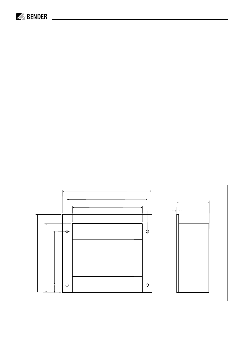
Dimension diagram
設置と配線
I
感電の危険!カップリングデバイスは、絶縁
監視装置を通して接地回路に接続されます。
絶縁監視装置に接続される全ての接地回路
は適切に安全に接続されていなければなり
ません。
I
設備損傷、怪我、及び火災のリスク!回路電
圧、電源電圧が正しいことを確認してくださ
い。配線は短絡/地絡に留意されていること
を確認してください。
i
カップリングデバイスが、活線回路に接続され
ている場合は、絶縁監視装置から端子
AK
又は
AK160
を決して外してはいけません。
i
DIN EN 45545-2:2016:
列車車輛への適用
DIN EN 45545-2
表2の要求事項が適用しない
周辺デバイスまでの水平距離
(
20 mm
以上)
と
垂直距離(
200 mm
以上)が保てない場合、それ
らはグループとして扱われます。
DIN EN 45545-2
の
4.3
項のグループに関する
ルールを参照のこと。
寸法図
220
200
178
76
6
178
125
22,5
190
ø 7
Dimensions in mm
AGH520S
AGH520S_D00073_04_M_DEEN/01.2021 5
mm
表示

Wiring diagram
Commissioning
•Prior to commissioning, check proper connec-
tion of the coupling devices.
•Only operate the coupling device in combinati-
on with ISOMETER®s listed in the wiring digram.
Standards
DIN EN 61800-5-1(VDE 0160-105-1)
Adjustable speed electrical power drive systems - part
5-1. Safety requirements - Electrical, thermal and ener-
gy (IEC 61800-5-1:2007);
German version EN 61800-5-1:2007
配線接続図
運用に際して
•運用開始の際には、カップリングデバイスが正
しく配線接続されてることを確認する。
•本製品は、必ず図中に記載のある絶縁監視装
置との組み合わせのみでご使用ください。
規格
DIN EN 61800-5-1(VDE 0160-105-1)
Adjustable speed electrical power drive systems - part
5-1. Safety requirements - Electrical, thermal and
ener-gy (IEC 61800-5-1:2007);
German version EN 61800-5-1:2007
AGH520SAnkoppelgerät
Coupling device
PE
L1
L2
L3
Un= 3AC 7,2 kV
ISOMETER® iso685-x(-B)
KEEL1 L2 L3
KEEL1 L2 AK
ISOMETER® IRDHx75-4xx
Oine Online
AGH520SAnkoppelgerät
Coupling device
ISOMETER® iso685-x(-B)
KEEL1 L2 L3
PE
L1
L2
L3
Un= 3AC 7,2 kV
KEEL1 L2 AK
ISOMETER® IRDHx75-4xx
6 AGH520S_D00073_04_M_DEEN/01.2021
AGH520S

Technical data
Insulation coordination acc. to IEC 60664-1
Rated insulation voltage....................................................AC 6,3 kV
Voltage test acc. to IEC 60664-1
Voltage impulse test (basic insulation) ..............................AC 35 kV
Overvoltage category.....................................................................III
AC voltage test (basic insulation)......................................AC 17,5kV
Partial discharge test...............................................................12 kV
Voltage ranges
Nominal system voltage Un......................................................0…7,2 kV
Nominal system voltage Unfor UL applications........................0…6,0 kV
Frequency range of Un......................................................DC 50…440 Hz
Internal DC resistance Ri..............................................................≥ 80 kΩ
Impedance Ziat 7,2 kV and 50 Hz ................................................ ≥6 MΩ
Environment EMC
Ambient temperatures
Operation....................................................................-10…+55 ºC
Operation UL-Applications..........................................-10…+45 °C
Storage.......................................................................-40…+70 °C
Classification of climatic conditions acc. to IEC 60721.......................3K23
Classification of mechanical conditions acc. to IEC 60721:
Stationary use (IEC 60721-3-3)................................................3M11
Transport (IEC 60721-3-2).........................................................2M4
Storage (IEC 60721-3-1)..........................................................1M12
Connection
Connection terminal 2 (medium voltage)................screw type terminals
Connection terminals 3-5.........................................screw type terminals
Connection properties rigid/flexible ...........0.2…4 mm²/0.2…2.5 mm²
AWG.............................................................................................24…12
Tightening torque......................................................................... 2.9 Nm
Other
Operating mode......................................................continuous operation
Mounting..............................................................................any position
Degree of protection, built-in components (DIN EN 60529)...............IP64
Degree of protection, terminals (DIN EN 60529)................................IP20
Type of enclosure.............................resin-encapsulated block in housing
Screw mounting ............................................................................4 x M5
Flammability class .................................................................. UL94 V-HB
Weight...........................................................................................4500 g
技術仕様
電気絶縁 (IEC 60664-1)
定格絶縁電圧 ...........................................................AC 6,3 kV
電圧テスト(IEC 60664-1)
電圧インパルステスト (基本絶縁).....................AC 35 kV
過電圧カテゴリー ............................................................... III
AC電圧テスト (基本絶縁) ................................ AC 17,5 kV
部分放電テスト ............................................................ 12 kV
適用電圧範囲
適用電圧範囲 Un.............................................................0…7,2 kV
適用電圧範囲 Un(UL-規格).................................. AC 0…6,0 kV
周波数範囲 Un .........................................................DC 50…400 Hz
DC-内部抵抗 Ri......................................................................≥80 kΩ
インピーダンス Zi(7,2 kV/50 Hz時)................................. ≥6 MΩ
環境 EMV
周囲温度
動作時....................................................................-10…+55 °C
動作時(UL適用時)............................................ -10…+45 °C
保管時 ....................................................................-20…+70 °C
使用天候的環境分類 (IEC 60721)..........................................3K23
使用機械的環境分類 (IEC 60721)
通常使用時 (IEC 60721-3-3)........................................... 3M11
輸送時 (IEC 60721-3-2) ........................................................2M4
保管時 (IEC 60721-3-1)..................................................... 1M12
接続
接続端子 2 (高圧側)......................................................ネジ式
接続端子 3-5......................................................................ネジ式
接続導体、単線/より線 ............... 0,2…4 mm²/0,2…2,5 mm²
AWG.............................................................................................24…12
締め付けトルク.................................................................... 2,9 Nm
その他
動作モード.....................................................................常時動作
設置方向..................................................................................自由
保護等級、本体 (DIN EN 60529) ..............................................IP64
保護等級、端子台 (DIN EN 60529) .........................................IP20
筐体...................................................................レジンにて保護
取り付け方法 ...............4 x M5(スクリューネジによる固定)
難燃性クラス ................................................................. .UL94 V-HB
重量 .......................................................................................... 4500 g
AGH520S
AGH520S_D00073_04_M_DEEN/01.2021 7

Alle Rechte vorbehalten.
Nachdruck und Vervielfältigung
nur mit Genehmigung des Herausgebers.
Bender GmbH & Co. KG
Postfach 1161 • 35301 Grünberg • Deutschland
Londorfer Str. 65 • 35305 Grünberg • Deutschland
Tel.: +49 6401 807-0 • Fax: +49 6401 807-259
E-Mail: [email protected] • www.bender.de
All rights reserved.
Reprinting and duplicating
only with permission of the publisher.
Bender GmbH & Co. KG
PO Box 1161 • 35301 Grünberg • Germany
Londorfer Str. 65 • 35305 Grünberg • Germany
Tel.: +49 6401 807-0 • Fax: +49 6401 807-259
E-Mail: [email protected] • www.bender.de
AGH520S_D00073_04_M_DEEN/01.2021 / pdf / © Bender GmbH & Co. KG, Germany – Subject to change! The specied standards take into account the edition valid until 01/2021 unless otherwise indicated.
問い合わせ先
Bender社日本総代理店
株式会社 プロトラッド
〒105-0011
東京都港区芝公園3-6-23 光輪会館
TEL 03-3431-7224
FAX 03-3431-7225
e-mail: [email protected]
Web : http://www.protrad.jp/
Table of contents
Other Bender Industrial Equipment manuals


