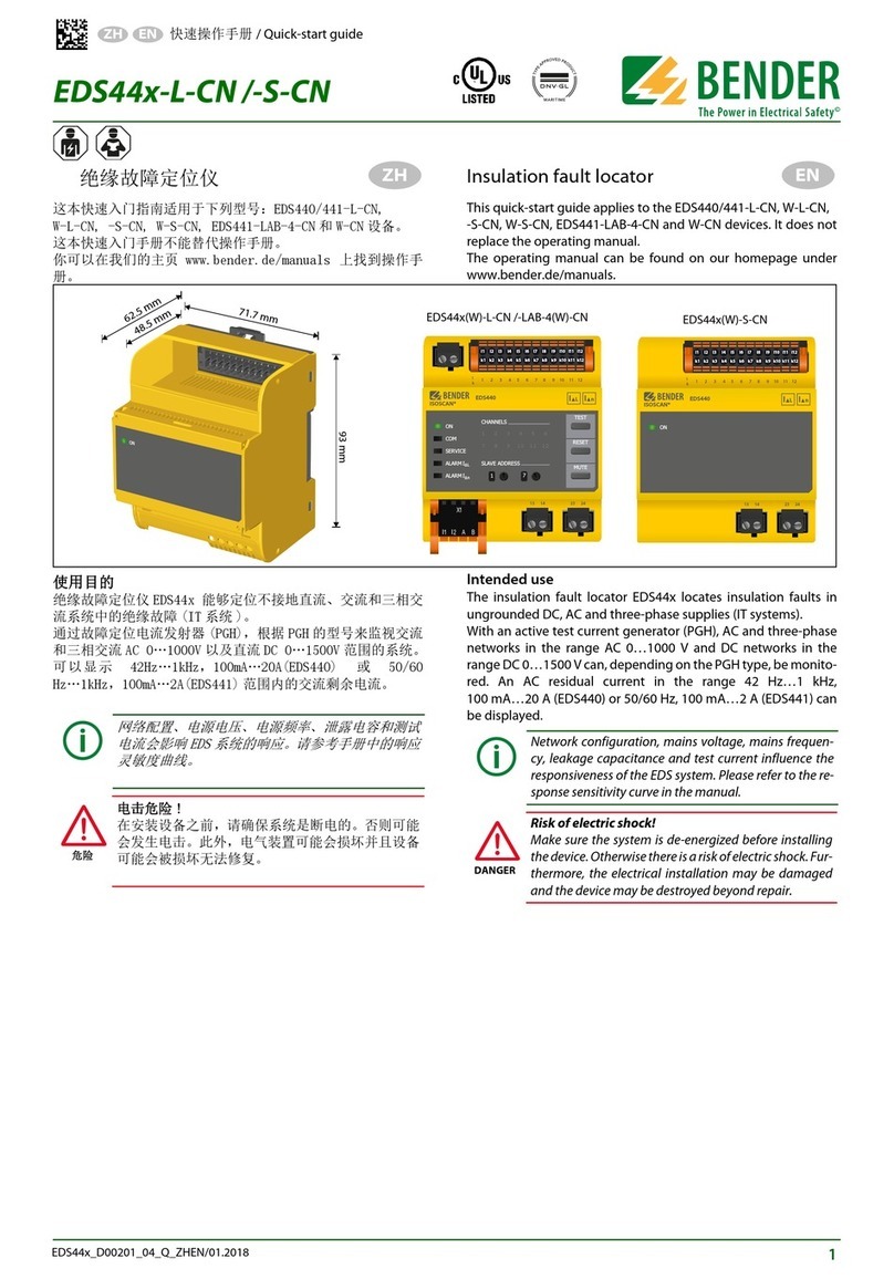
Bender ISOMETER isoBAT425 User manual

Manual EN
ISOMETER® isoBAT425
Insulation monitoring device with coupling impedance ZE420
for batteries up to DC 500
Software version: D0560
isoBAT425_D00308_05_M_XXEN/09.2023

2 isoBAT425_D00308_05_M_XXEN/09.2023

ISOMETER® isoBAT425
Table of contents
1General information...........................................................................................6
1.1 How to use the manual.................................................................................................................................6
1.2 Indication of important instructions and information.......................................................................6
1.3 Signs and symbols...........................................................................................................................................6
1.4 Service and Support....................................................................................................................................... 6
1.5 Training courses and seminars...................................................................................................................7
1.6 Delivery conditions......................................................................................................................................... 7
1.7 Inspection, transport and storage.............................................................................................................7
1.8 Warranty and liability.....................................................................................................................................7
1.9 Disposal of Bender devices..........................................................................................................................8
1.10 Safety.................................................................................................................................................................... 8
2unction...............................................................................................................9
2.1 Intended use......................................................................................................................................................9
2.2 Device features................................................................................................................................................. 9
2.3 Functional description...................................................................................................................................9
2.3.1 ZE420 coupling impedance...................................................................................................................... 10
2.3.2 Measured values............................................................................................................................................10
2.3.3 Monitoring of the insulation resistance and the system leakage capacitance.......................11
2.3.4 Undervoltage/overvoltage monitoring................................................................................................ 11
2.3.5 Messpulsperiodendauer und Ansprecheigenzeiten........................................................................ 12
2.3.6 Fault diagnosis............................................................................................................................................... 13
2.3.7 Error codes.......................................................................................................................................................14
2.3.8 Connection monitoring.............................................................................................................................. 14
2.3.9 Reset and test.................................................................................................................................................15
2.3.10 Stop mode....................................................................................................................................................... 17
2.3.11 Start with alarm (S.AL).................................................................................................................................17
2.3.12 Measuring and response times................................................................................................................17
2.3.13 Password protection (on, OFF)................................................................................................................ 18
2.3.14 Fault memory..................................................................................................................................................18
2.3.15 History memory HiS..................................................................................................................................... 18
2.3.16 Digital interface..............................................................................................................................................18
3Installation, connection and commissioning.................................................20
3.1 Dimensions...................................................................................................................................................... 20
3.2 Installation........................................................................................................................................................20
isoBAT425_D00308_05_M_XXEN/09.2023 3

Table of contents
3.3 Connection.......................................................................................................................................................21
3.4 Commissioning...............................................................................................................................................22
4Operation.......................................................................................................... 24
4.1 Operating and display elements.............................................................................................................24
4.2 Menu overview...............................................................................................................................................26
4.3 Displaying measured values..................................................................................................................... 27
4.4 Setting the response values (AL)............................................................................................................ 28
4.4.1 Setting the response values for monitoring the insulation resistance......................................28
4.4.2 Setting the response values for undervoltage and overvoltage.................................................28
4.4.3 Response values overview.........................................................................................................................28
4.5 Configuring fault memory, alarm relays, and interfaces (out)......................................................29
4.5.1 Configuring the relays.................................................................................................................................29
4.5.2 Assigning the alarm messages to the relays...................................................................................... 29
4.5.3 Activating or deactivating fault memory.............................................................................................30
4.5.4 Configuring interface...................................................................................................................................30
4.6 Setting delay times and self test cycles (t).......................................................................................... 31
4.7 Setting device control parameters (SEt)...............................................................................................31
4.8 Reset to factory settings.............................................................................................................................32
4.9 Showing and deleting the history memory........................................................................................32
4.10 Querying software version (InF).............................................................................................................. 32
5Data access via RS-485 interface.....................................................................33
5.1 Data access using the BMS protocol..................................................................................................... 33
5.2 Data access using the Modbus RTU protocol.................................................................................... 33
5.2.1 Reading out the Modbus register from the ISOMETER®.................................................................33
5.2.2 Writing the Modbus register (parameter setting).............................................................................34
5.2.3 Exception code...............................................................................................................................................35
5.3 Modbus register assignment.................................................................................................................... 36
5.3.1 Modbus measured value registers......................................................................................................... 36
5.3.2 Modbus parameter register...................................................................................................................... 39
5.4 IsoData data string....................................................................................................................................... 43
6Technical data...................................................................................................44
6.1 Technical data isoBAT425.......................................................................................................................... 44
6.2 Technical data ZE420...................................................................................................................................48
6.3 Connection.......................................................................................................................................................49
6.4 Standards and certifications..................................................................................................................... 50
6.5 Ordering data..................................................................................................................................................50
4 isoBAT425_D00308_05_M_XXEN/09.2023

General information
1 General information
1.1 How to use the manual
ADVICE
This manual is intended for qualified personnel working in electrical engineering and electronics!
Part of the device documentation in addition to this manual is the enclosed supplement "Safety
instructions for Bender products".
ADVICE
Read the operating manual before mounting, connecting and commissioning the device. Keep the
manual within easy reach for future reference.
1.2 Indication of important instructions and information
DANGER
Indicates a high risk of danger that will result in death or serious injury if not avoided.
WARNING
Indicates a medium risk of danger that can lead to death or serious injury if not avoided.
CAUTION
Indicates a low-level risk that can result in minor or moderate injury or damage to property if not
avoided.
ADVICE
Indicates important facts that do not result in immediate injuries. They can lead to malfunctions if the
device is handled incorrectly.
Information can help to optimise the use of the product.
1.3 Signs and symbols
Disposal Protect from moisture Protect from dust
Temperature range Recycling RoHS directives
1.4 Service and Support
Information and contact details about customer service, repair service or field service for Bender devices are
available on the following website: Fast assistance | Bender GmbH & Co. KG.
6 isoBAT425_D00308_05_M_XXEN/09.2023

ISOMETER® isoBAT425
1.5 Training courses and seminars
Regular face-to-face or online seminars for customers and other interested parties:
www.bender.de > know-how > seminars.
1.6 Delivery conditions
The conditions of sale and delivery set out by Bender GmbH & Co. KG apply. These can be obtained in printed
or electronic format.
The following applies to software products:
Die Elektroindustrie
‘Software clause in respect of the licensing of standard software as part of deliveries,
modifications and changes to general delivery conditions for products and services in the
electrical industry’
1.7 Inspection, transport and storage
Check the shipping and device packaging for transport damage and scope of delivery. In the event of
complaints, the company must be notified immediately, see "www.bender.de > service & support.".
The following must be observed when storing the devices:
1.8 Warranty and liability
Warranty and liability claims for personal injury and property damage are excluded in the case of:
•Improper use of the device.
•Incorrect mounting, commissioning, operation and maintenance of the device.
•Failure to observe the instructions in this operating manual regarding transport, commissioning, operation
and maintenance of the device.
•Unauthorised changes to the device made by parties other than the manufacturer.
•Non-observance of technical data.
•Repairs carried out incorrectly.
•The use of accessories or spare parts that are not provided, approved or recommended by the
manufacturer.
•Catastrophes caused by external influences and force majeure.
•Mounting and installation with device combinations not approved or recommended by the manufacturer.
This operating manual and the enclosed safety instructions must be observed by all persons working with the
device. Furthermore, the rules and regulations that apply for accident prevention at the place of use must be
observed.
isoBAT425_D00308_05_M_XXEN/09.2023 7

General information
1.9 Disposal of Bender devices
Abide by the national regulations and laws governing the disposal of this device.
For more information on the disposal of Bender devices, refer to
www.bender.de > service & support.
1.10 Safety
If the device is used outside the Federal Republic of Germany, the applicable local standards and regulations
must be complied with. In Europe, the European standard EN 50110 applies.
DANGER Risk of fatal injury due to electric shock!
Touching live parts of the system carries the risk of:
•Risk of electrocution due to electric shock
•Damage to the electrical installation
•Destruction of the device
Before installing the device and before working on its connections, make sure that the installation
has been de-energised. The rules for working on electrical systems must be observed.
8 isoBAT425_D00308_05_M_XXEN/09.2023

ISOMETER® isoBAT425
2 unction
2.1 Intended use
This ISOMETER® is intended for monitoring the insulation resistance RF as well as the voltage of a battery
during its assembly from individual battery cells. The ISOMETER® monitors the insulation resistance of batteries
with nominal system voltages of DC 0…400 . The maximum permissible system leakage capacitance is 1 μF.
Based on the measured values obtained, it is possible to determine the type and location of an insulation fault.
In order to meet the requirements of the applicable standards, customised parameter settings must be made
on the equipment in order to adapt it to local equipment and operating conditions. Please heed the limits of
the range of application indicated in the technical data.
Any other use or a use that goes beyond this constitutes improper use.
If the ISOMETER is installed inside a control cabinet, the insulation fault message must be audible and/or
visible to attract attention.
2.2 Device features
•Monitoring of the insulation resistance RF to earth
•Monitoring of the battery voltage Un between the terminals “L+” and “L–”
•Configurable measuring frequency for adjustment to the physical characteristics of the battery
•Measuring the DC residual voltages UL+e (between L+ and earth) and UL–e (between L– and earth)
•Selectable start-up delay, response delay and delay on release
•Alarm output via LEDs (“AL1”, “AL2”), display, and alarm relays (“K1”, “K2”)
•Automatic device self test
•Selectable n/c or n/o relay operation
•Measured value indication via multi-functional LC display
•Activatable fault memory
•Locating the faulty conductor L+/L–, i.e. the distribution of the insulation resistance RF between terminals
“L+” and “L–”
•Monitoring and automatic adjustment to the system leakage capacitance Ce up to 4 μF
•Continuous connection monitoring of terminals “L+”, “L–” and “E”
•Two separately adjustable response value ranges from 10 kΩ to 5 MΩ (prewarning, alarm)
•Device supply via wide-range power supply
•RS-485 (galvanically isolated) including the following protocols:
– BMS (Bender measuring device interface) for the data exchange with other Bender devices
– Modbus RTU
– IsoData (for continuous data output)
•Password protection against unauthorised changing of parameters
2.3 unctional description
The isoBAT425 ISOMETER® is intended for monitoring the insulation resistance RF as well as the voltage Un of a
battery during its assembly from individual battery cells. The ISOMETER® measures the insulation resistance RF
and the system leakage capacitance Ce of the battery to earth. Additionally, it measures the battery voltage Un
between L+ and L–, as well as the residual voltages UL+e (UL+ to earth) and UL–e (UL– to earth).
isoBAT425_D00308_05_M_XXEN/09.2023 9

Function
In the first step, the battery is assembled in two parallel strings (plus and minus string) which are not
interconnected. During the second step, the two strings are connected to form a complete battery by means
of another battery.
The resulting measured values allow diagnosing the type and location of the insulation fault. In the LC display,
the faulty conductor is displayed with a plus or a minus sign preceding the value RF.
The detected fault is assignable to an alarm relay via the menu. If the values RF or Un violate the activated
response values in “AL” menu, the LEDs and the alarm relays “K1” and “K2” issue an alarm according to the
alarm assignment settings in the “out” menu. In addition, the operating mode of the alarm relay can be set and
the fault memory “M” can be activated in this menu.
If the values RF or Un do not violate their respective release value (response value plus hysteresis) for the period
toff without interruption, the alarm relays will switch back to their initial position and the alarm LEDs will go out.
If the fault memory is activated, the alarm relays remain in alarm condition and the LEDs light until the reset
button “R” is pressed or the supply voltage Us is interrupted.
The device function can be tested using the test button “T”.
Parameters are assigned to the device via the LCD and the control buttons on the front panel; this function can
be password-protected. The parameters of the device can be set via Modbus RTU.
2.3.1 ZE420 coupling impedance
In the case of open battery strings, the ZE420 coupling impedance provides a low-resistance connection
(10 kΩ) between terminals “L+” and “L−”, necessary for the measuring functions of the ISOMETER®. In the case
of closed batteries, the resistance is optional due to the internal resistance of the battery.
In addition to this resistance, there is also a 1.5 mA current limitation. It starts above Un = 25 and increases
the internal resistance of the coupling impedance. For this reason, in the event of a cross fault, the system
connection monitoring may be additionally triggered but, at the same time, the responsivity of the cross fault
detection is increased.
In addition, the coupling impedance contains two capacitances for a necessary minimum leakage capacitance
to earth.
2.3.2 Measured values
Parameters measured by the ISOMETER®
Parameter Description Unit
RFIsolationswiderstand gegen Erde kΩ
UnDC system voltage between L+ and L− V
UL+e DC residual voltage between L+ and earth V
UL−e DC residual voltage between L− and earth V
Faulty
ondu tor
Distribution of the insulation resistan e RF between terminals “L+” and “L−”.
In the LC display, the fault lo ation is marked with a plus or a minus sign
pre eding the value RF.
%
10 isoBAT425_D00308_05_M_XXEN/09.2023

ISOMETER® isoBAT425
Measured value ranges and resolution
Value Interface Value range Resolution
1 kΩ 999 kΩ 1 kΩ
LCD 1.0 MΩ 10.0 MΩ 0.1 MΩ
BMS 1 kΩ 20000 kΩ 1 kΩ
R
Modbus, IsoData 1 kΩ 20000 kΩ 1 kΩ
0 V ±99.9 V 0.1 V
LCD ±100 V ±500 V 1 V
BMS 0 V 500 V 1 V
U
Modbus, IsoData 0 V ±500 V 0.1 V
0 nF 999 nF 1 nF
LCD 1.00 μF 9.99 μF 0.01 μF
BMS 0 nF 9990 nF 1 nF
C
Modbus, IsoData 0 nF 9990 nF 1 nF
2.3.3 Monitoring of the insulation resistance and the system leakage capacitance
The insulation resistance RF as well as the system leakage capacitance Ce to earth are measured. The results are
the total values from the sub-components RF1 || RF2 as well as Ce1 + Ce2. The system leakage capacitance value
Ce is only updated above RF = 10 kΩ.
When the insulation resistance RF reaches or falls below the threshold values R1 (prewarning) or R2 (alarm), an
alarm message is issued. Parameters R1 and R2 can be found in the response value menu “AL” (see “Response
values overview”, page 28). If by means of the measured voltages the faulty conductor can be assigned to
the plus or the minus string, only the corresponding “L+” or “L−” alarm will be issued. Otherwise, both alarms
are issued together.
The system leakage capacitance Ce is monitored on its compliance with the maximum permissible value for the
ISOMETER®. If the measured value of the system leakage capacitance Ce exceeds 4 μF, the device error “E.07”
with the alarm message “Device error” is issued.
The measurement method requires a low-resistance connection between terminals “L+” and “L−”. If the
battery strings are still separated from each other, the connection will be established via the coupling
impedance ZE420. The 12 kΩ internal resistance of the coupling impedance is included in the measured value
RF. If RF is below 100 kΩ, a measured value deviation of approx. +2 kΩ must be expected. If the battery strings
are connected to form a complete battery, the internal resistance of the battery establishes the low-resistance
connection and the deviation due to the coupling impedance is omitted.
2.3.4 Undervoltage/overvoltage monitoring
The nominal system voltage Un is 400 . With an overvoltage of 25 %, a maximum of 500 are permissible. The
DC system voltage Un is measured in and RMS. The root-mean-square value is a true RMS value and is only
required for overload detection (over range) of the system coupling. In addition, the DC residual voltages UL+e
as well as UL−e to earth are determined. The voltage values on the LC display and the interface are averaged
isoBAT425_D00308_05_M_XXEN/09.2023 11

Function
to improve the resolution and are time-delayed. The comparators of the system voltage monitoring use the
non-delayed, non-averaged system voltage. Therefore, minor deviations between the response of the voltage
monitoring and the indicated voltage value are possible.
The parameters (U1˂, U1˃, U2˂ and U2˃) for monitoring the system voltage Un can be set in the response
value menu “AL” (see “Setting the response values (AL)”, page 28). The maximum undervoltage value
is limited by the overvoltage value. If the nominal system voltage Un reaches, falls below or exceeds the
limit values (U˂ or U˃), an alarm will be signalled. The alarm will be deleted when the threshold values plus
hysteresis are no longer violated.
The image below shows the operating mode of the voltage comparators with the resulting messages.
Figure 2-1: oltage monitoring limits
2.3.5 Messpulsperiodendauer und Ansprecheigenzeiten
In the “sEt” menu, the measuring pulse period duration TMP can be configured with the parameter “t ”.
The maximum operating times tae (see “Measuring and response times”, page 17) of the monitoring
of the insulation resistance RF, the cross fault RC as well as the connection to earth (E.01) and the battery
(E.02) depend on it. The modifiable measuring pulse period duration allows adjusting the ISOMETER® to the
insulation behaviour of the battery.
Measuring pulse period durations which are marked with the “auto” symbol switch automatically to the
longest measuring pulse period duration as long as the message “Battery voltage Un is ok” is indicated. The
following table shows the maximum operating times tae for the different alarms and measuring pulse period
durations TMP.
12 isoBAT425_D00308_05_M_XXEN/09.2023

ISOMETER® isoBAT425
TMP RFRCE.01 E.02
0.8 s 3.5 s 3.0 s 2.1 s 6.0 s
2.0 s 8.0 s 3.0 s 2.1 s 6.0 s
4.0 s 16.0 s 3.0 s 2.1 s 15.0 s**
8.0 s 32.0 s 3.0 s 2.1 s 30.0 s*
* The value only applies to Ce1 or Ce2 > 400 nF. Below this value, the absence of just one system connection is not reliably
detected.
** The value only applies to one-sided Rf ≤ 1.5 MΩ. Above this value, the absence of just one system connection is not
reliably detected.
2.3.6 ault diagnosis
2.3.6.1 Insulation fault to earth
The displayed value RF of the ISOMETER® is the total insulation resistance RF to earth. The polarity and the
amount of residual voltages UL+e and UL−e are an indicator of insulation fault location.
If the battery strings are not interconnected yet, the residual voltages UL+e and UL−e are almost identical and
the nominal battery voltage Un is about 0 , it is very likely that the insulation fault is only located in one string.
The polarity of the residual voltages marks the affected string. The affected battery cell can be calculated by
means of the residual voltages UL+e or UL−e and the ISOMETER® internal resistance Ri = 120 kΩ:
Ucell = ULxe × (1 + RF / Ri)
If there is an additional insulation fault in the other string, determining the cell is almost impossible, since
several variables, depending on location and size of the insulation fault, determine the residual voltages. If the
battery strings are connected to form a complete battery, the measured value “Fault location%” indicates the
fault location. Clear assignment is only possible in the event of a single insulation fault. The value can range
between −100 % and +100 %. The sign indicates the string affected. When the fault is located in the middle of
the battery, the fault location is 0 %.
2.3.6.2 Insulation fault between the battery strings (cross fault)
The insulation fault RC (cross fault) creates a connection between the unconnected strings and has no
connection to earth. It can be detected via the Un value of the voltage measurement. If Un reaches or exceeds
the comparator value UCrossL, the overvoltage alarm is activated.
Depending on the fault location of the insulation fault RC, an unloaded voltage on the same level as the
voltage in a battery cell up to the maximum voltage of the series connection of both battery strings can
occur. RC directly at the coupling points is not detectable due to the absence of voltage. Since the coupling
impedance contains a current-limited resistance of 10 kΩ, which is connected in parallel to the series internal
resistance of 240 kΩ of the ISOMETER®, the nominal system voltage Un resulting from the insulation fault RC is
loaded with this resistance. For RC > 10 kΩ, exceeding half the voltage of a battery cell can be considered as
lower limit for the fault detection.
Note that the internal resistance of the coupling impedance is only linear up to approx. 1.5 mA and from
then on limits the current to this value. In connection with the non-linear internal resistance of the coupling
impedance, in case of high-resistance values of RC the device error / coupling error “E.02” can occur
simultaneously with the overvoltage alarm.
isoBAT425_D00308_05_M_XXEN/09.2023 13

Function
2.3.6.3 Battery voltage
The system voltage Un is monitored with the voltage comparators described above. The insulation fault
RC between the unconnected strings as well as the completion of the battery can be detected via these
comparators.
2.3.7 Error codes
In the event of a device error the display shows the respective error code.
Overview of some error codes
Error code Meaning
E.01
PE connection error
The onne tion of “E” or “KE” to earth is interrupted.
Action Che k onne tion, eliminate error. The error ode will be erased automati ally on e the
error has been eliminated.
E.02
System connection error
The internal resistan e of the system is too high or the onne tion of “L+” or “L–” to the system is
interrupted. The terminals “L+” and “L–” are onne ted in orre tly.
Action Che k onne tion, eliminate error. The error ode will be erased automati ally on e the
error has been eliminated.
E.05
Measurement error
Due to system interferen es or a devi e error, the insulation measured value is no longer updated.
Prewarning and alarm are set for the insulation measured value at the same time.
Calibration invalid after software update
“E.05” appears together with “E.08”: The software is not ompatible to the alibration of the devi e.
Action Install the previous software version or have the devi e alibrated at the fa tory.
E.07
Permissible system leakage capacitance Ce exceeded
The devi e is not suitable for the present network leakage apa itan e Ce.
Action Uninstall the devi e.
E.08 Calibration error
Action Che k onne tion, eliminate error. If the error is still present, there is a devi e error.
Internal device errors “E.xx” can be caused by external disturbances or internal hardware errors. If the error
message occurs again after the device has been restarted or after a reset to the factory settings (menu item
“FAC”), the device must be repaired. After the fault has been eliminated, the alarm relays switch back either
automatically or when the reset button is pressed. The self test can take a few minutes.
2.3.8 Connection monitoring
E-KE monitoring
The E-KE monitoring checks the connection between terminals “E” and “KE” and thereby ensures the
connection to earth of the ISOMETER® and the battery enclosure. An error is reported with the code E.01
and device error. It operates constantly in the background and does not affect the measuring function of the
device.
14 isoBAT425_D00308_05_M_XXEN/09.2023

ISOMETER® isoBAT425
System connection monitoring
The system connection monitoring monitors the connection of terminals “L+” and “L−” to the battery by
means of the coupling impedance ZE420. An error is reported with the code E.02 and device error. The
monitoring requires a resistance smaller than 12 kΩ and a system leakage capacitance Ce larger than 80 nF
between terminals “L+” and “L−”. In the case of separated battery strings, the coupling impedance ensures
that these minimum requirements are fulfilled. In the case of closed battery strings, the battery provides the
required connection between “L+” and “L−” with its low-ohmic internal resistance. The system connection
monitoring operates constantly in the background and does not influence the measuring function of the
ISOMETER®.
Above a measuring pulse period duration of 2 s, a missing connection to “L+” or “L−” is only reliably detected
under the conditions specified in chapter “Messpulsperiodendauer und Ansprecheigenzeiten”, page 12.
The system connection monitoring can be deactivated with the “nEt” parameter in the “SEt” menu. See chapter
“Setting device control parameters (SEt)”, page 31.
2.3.9 Reset and test
2.3.9.1 External test/reset input and stop mode
The fault memory (“M”) is deleted by briefly connecting (0.2 s < t < 1.5 s) the terminal “T/R” to earth (terminal
“E”). If the connection time exceeds 1.5 s, the manual self test starts. If the terminal “T/R” is still connected to
earth after the device self test has been completed, the ISOMETER® changes to stop mode (“StP” indication on
the display) and the measuring function is deactivated.
2.3.9.2 Reset
The following options trigger a reset:
•Briefly pressing (0.2 s < t < 1.5 s) the external “T/R” button.
If the button is held (t > 1.5 s), a test follows the reset.
•Pressing and holding (t > 1.5 s) the “R” button.
•Sending a reset command via the interface.
•Activating stop mode.
In doing so, alarms that are no longer active are deleted from the fault memory.
2.3.9.3 Manual self test
During a manual self test (duration approx. 30 s), the measuring functions of the ISOMETER® are deactivated.
During the test, the “AL1” and “AL2” LEDs are lit, the message “tES” appears on the display and all self-test
functions described in the self-test section are carried out. An alarm which makes the LEDs flash overrides the
lighting of the LEDs.
The manual self test can be triggered as follows:
Holding the external “T/R” button (>1.5 s):
– A reset is carried out before the test so that alarms which are no longer active are deleted from the fault
memory.
– The LCD shows “tES” and “CAL”.
Holding the “T” button (>1.5 s):
– The LCD shows all elements as long as this button is pressed, afterwards “tES” flashes.
– A reset is carried out after the test.
isoBAT425_D00308_05_M_XXEN/09.2023 15

Function
Sending a test command via the interface (COM):
– The LCD shows “tES” and “CAL”.
– A reset is carried out after the test.
If triggering via the “T/R” button, the alarms remain active during the test (except the “Device fault” alarm). In
addition, the message “test” switches the alarm relays if it is assigned to the alarm relays in the “out” menu.
After the manual self test, which can only be exited when exiting the stop mode, the message “test”, which
may be displayed, will also be deleted from the fault memory.
2.3.9.4 Automatic self test
During an automatic test (duration approx. 30 s), the measuring functions of the ISOMETER® are deactivated.
In the “t” menu (see chapter 4.6) the parameter “test” can be used to set the repetition time for an automatic
test. If this timer is the trigger, only the message “tES” will be indicated on the display. No alarm is issued via
the LEDs, the alarm relays or the interface. No reset is carried out.
A manual self test resets the timer for the automatic self test.
2.3.9.5 Self test
The ISOMETER® has the following self test functions:
•Checking the operating system (background test)
•Checking the connection of terminals “E” and “KE” to earth (background test, continuous)
•System connection monitoring (background test, continuous)
•Checking the function of the measuring equipment
Some of the self-test functions are executed constantly or time-controlled in the background, others are only
executed on request.
The following sources can request a self-test:
•“T” button on the ISOMETER®
•External “T/R” button
•Serial interface
•Timer for automatic self test, configurable with the “test” parameter in the “t” menu
•Device start when “S.Ct” parameter = on (in the “SEt” menu)
During a self test started by one of the sources named above, the measuring function is temporarily
deactivated. The background tests do not influence the measuring function.
2.3.9.6 Checking the operating system
The operating system check includes:
•Check sum verification of the program memory
•Error-free program sequence with stack check
•Parameter values check
•μC initialisation check
The μC initialisation check is run at least every 5 min. The data RAM memory, the check sum of the program
memory and the content of the parameter memory are checked at least once an hour. These tests run in the
background and do not influence the measuring function of the ISOMETER®.
16 isoBAT425_D00308_05_M_XXEN/09.2023

ISOMETER® isoBAT425
2.3.10 Stop mode
The stop mode stops the measuring functions of the ISOMETER®. The measuring pulse voltage is 0 and
the input resistance of the system coupling has a high resistance. The LCD displays the message “StP”. The
message “test” is set and all other messages are deleted.
The stop mode can be started by permanently closing the external “T/R” button or via the interface and ends
when opening the “T/R” button or by releasing it via the interface. The control of the stop mode via the “T/R”
button and the interface is an OR operation.
When the stop mode ends, a waiting time (2 s) starts so that the measured value recording settles before new
threshold value comparisons are allowed.
If the ISOMETER® starts with an alarm (“out” menu, alarm assignment “S.AL” set to “on”) the released alarms are
set and the measured resistance values are reset to their initial value. The alarm assignment S.AL (i.e. Start
with an alarm) should be set identically for both alarm relays. When operating without “S.AL”, no alarms
are set and the ISOMETER® starts with the maximum measured resistance value.
2.3.11 Start with alarm (S.AL)
The S.AL function allows a device start with set alarm messages. This function is activated in the “out” menu,
in the alarm relay alarm assignments “r1” and “r2” by means of the parameter “S.AL”. For useful operation with
this function, both alarm relays should have “S.AL” activated and operate in n/c mode.
If “S.AL” is activated during device start, all alarms of the released threshold value comparisons are set and the
measured resistance values are initialised with 0 Ω. The alarms of the individual threshold value comparisons
remain set until the respective measured value has reached the GO-state. No hysteresis is taken into account
and the alarms do not remain stored in the fault memory.
A measured value that reaches the GO-state after the device has started triggers the history memory in case of
a previous threshold value violation and the alarm remains stored in the fault memory.
2.3.12 Measuring and response times
The measuring time is the period essential for the detection of the measured value. The measuring time is
reflected in the operating time tae. For the insulation resistance measured value, it is mainly determined by the
necessary measuring pulse duration, which depends on the insulation resistance RF and the system leakage
capacitance Ce of the system to be monitored. The measuring pulse is generated by the measuring pulse
generator integrated in the ISOMETER®. The measuring times for Ce, UL+e, UL−e and R % are synchronous.
System disturbances may lead to extended measuring times. In contrast, the time for the system voltage
measurement Un is independent and considerably shorter.
Operating time tae
The operating time tae is the time required by the ISOMETER® to determine the measured value. The insulation
resistance measured value depends on the insulation resistance RF and the system leakage capacitance Ce.
Response delay ton
The response delay ton is set uniformly for all alarm messages in the “t” menu using the parameter “ton”, while
each alarm message specified in the alarm assignment has its own timer for ton. This delay can be used for
interference suppression in the case of short measuring times.
An alarm message will only be signalled when a limit value of the respective measured value is violated for the
duration of ton. Each time the limit value is violated within the time ton, the response delay “ton” restarts.
isoBAT425_D00308_05_M_XXEN/09.2023 17

Function
Total response time tan
The total response time tan is the sum of the operating time tae and the response delay ton.
Delay on release toff
The delay on release toff can be set uniformly for all alarm messages using the parameter “toff”, while each
alarm message specified in the alarm assignment has its own timer for toff.
An alarm message will be signalled until the limit value of the respective measured value is no longer violated
(including hysteresis) for the duration of toff without interruption. Each time a limit value is no longer violated
during toff, the delay on release “toff” restarts.
Start-up delay t
After connecting the supply voltage US, the alarm output is suppressed for the time set in parameter
“t” (0…10 s).
2.3.13 Password protection (on, O )
If password protection is activated (on), settings can only be made after entering the password (0...999). For its
activation, see chapter 4.7.
2.3.14 ault memory
Disabled (O )
The LEDs and relays signal the fault as long as it is detected.
Enabled (ON)
The LEDs and relays signal the fault until a reset is performed or the supply voltage Us is disconnected.
2.3.15 History memory HiS
The history memory saves exclusively the measured values for the first fault. The history memory must first be
cleared before new measured values can be saved.
The values checked in the table in section “Displaying measured values”, page 27 can be saved.
2.3.16 Digital interface
The ISOMETER® uses the serial hardware interface RS-485 with the following protocols:
•BMS
The BMS protocol is an essential component of the Bender measuring device interface (BMS bus protocol).
Data transmission generally makes use of ASCII characters.
•Modbus RTU
Modbus RTU is an application layer messaging protocol, and it provides master/slave communication
between devices that are connected via bus systems and networks. Modbus RTU messages have a 16-bit
CRC (cyclic redundant checksum), which guarantees reliability.
18 isoBAT425_D00308_05_M_XXEN/09.2023

ISOMETER® isoBAT425
•IsoData
The ISOMETER® sends an ASCII data string with a cycle of approximately 1 second. Communication with
the ISOMETER® in this mode is not possible, and no additional sender may be connected via the RS-485 bus
cable. The ASCII data string for the ISOMETER® is described in chapter 5.4.
The IsoData protocol can be terminated by sending the command “Adr3” during a transmission pause
of the ISOMETER .
The parameter address, baud rate and parity for the interface protocols are configured in the “out” menu.
With “Adr = 0”, the menu entries baud rate and parity are not shown in the menu and the IsoData protocol
is activated.
With a valid bus address (i.e. not equal to 0), the menu item “baud rate” is displayed in the menu. The
parameter value “---” for the baud rate indicates the activated BMS protocol. In this case, the baud rate
for the BMS protocol is set to 9600 baud. If the baud rate is set unequal to “---”, the Modbus protocol with
configurable baud rate is activated.
isoBAT425_D00308_05_M_XXEN/09.2023 19

Installation, connection and commissioning
3 Installation, connection and commissioning
3.1 Dimensions
36
93
74.5
90 45 70.5
47.5
31.1
Figure: Dimension diagram (in mm)
3.2 Installation
Figure: DIN rail mounting (left) or screw mounting (right)
20 isoBAT425_D00308_05_M_XXEN/09.2023
Other manuals for ISOMETER isoBAT425
2
Table of contents
Other Bender Industrial Equipment manuals

