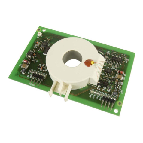
Installation instructions of measuring CT
I Caution! Device damage due to high induction
currents! High currents can be induced into the
conductor loop due to the AC/DC sensitive meas-
uring technology used. Do not route protective
conductors and low-resistance conductor loops
through the measuring current transformer!
I Caution!Device damage due to interference
pulses! The connecting cable (supply, analogue
interface ...) must not be routed directly past the
current transformer core.
I Caution!Risk of injury due to accessible live
conductors! The measuring current transform-
er must be connected to the corresponding
evaluator before the first use and before com-
missioning of the monitored system.
i
Application in railway vehicles / DIN EN
45545-2:2016: If the horizontal or vertical dis-
tance to adjacent components which do not
meet the requirements in table 2 of DIN EN
45545-2 is less than 20 mm or less than 200 mm
respectively, they are to be regarded as grouped.
Refer to DIN EN 45545-2 chapter 4.3 Grouping
rules.
i
Do not route any shielded cables through the
measuring current transformer.
The measuring current transformer must be connec-
ted to the corresponding evaluator before the first
use and before commissioning of the monitored sys-
tem.
All current-carrying cables must be routed through the meas-
uring current transformer. Never route an existing protective
conductor through the measuring curre nt transformer.
L1
L2
L3
N
The cables must be aligned with the centre of the measuring
current transformer.
*
The primary conductors may only be bent from the specified
minimum distance. The minimum bending radius specified by
the manufacturers for the conductors used must be observed.
Distance to 90° angle = 2 x outside diameter
Technical data
Measuring circuit
Internal diameter measuring CTs ......... see dimension diagrams
Rated current I.............................................................................
CTBC20 when IΔn = 30 mA ...............................................40 A
CTBC20 when IΔn = 300 mA .............................................63 A
CTBC20P...........................................................................80 A
CTBC35 when IΔn = 30 mA ...............................................80 A
CTBC35 when IΔn = 300 mA ...........................................125 A
CTBC35P.........................................................................160 A
CTBC60 when IΔn = 30 mA .............................................160 A
CTBC60 when IΔn = 300 mA ...........................................250 A
CTBC60P.........................................................................320 A
CTBC120 when IΔn = 100 mA .........................................330 A
CTBC120P when IΔn = 100 mA .......................................630 A
CTBC210 when IΔn = 300 mA .........................................630 A
CTBC210P when IΔn = 100 mA .......................................630 A
CTBC210P when IΔn = 300 mA .....................................1000 A
Measurement accuracy.......................................................±1 %
Test winding.......................................................................... yes
Rated continuous thermal current Icth ...................................30 A
Rated short-time thermal current Ith............................ 2.4 kA/1 s
Rated dynamic current Idyn .........................................6 kA/40 ms
LINETRAXX® CTBC series
CTBC-series_D00336_02_M_XXEN/09.2020 3
