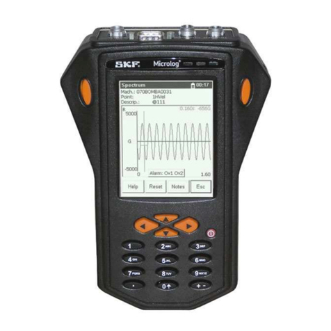
SKF MicroVibe P CMVL 3860-ML User manual

SKF MicroVibe P™
CMVL 3860-ML
Portable Vibration Meter
User Manual P/N 32178100-EN
Revision A
User Manual
WARNING! Not certified for use in hazardous locations.
Read this manual before using this product. Failure to follow the instructions and safety precautions in
this manual can result in serious injury. Keep this manual in a safe location for future reference.
Copyright ©2009
by SKF Reliability Systems
All rights reserved.
5271 Viewridge Court, San Diego, CA 92123-1841 USA
Telephone: (858) 496-3400, Fax: (858) 496-3531
Customer Service: 1-800-523-7514

SKF Reliability Systems
For additional information on SKF Reliability Systems products, contact:
SKF Reliability Systems
5271 Viewridge Court • San Diego, California 92123 USA
Telephone: +1 858-496-3400 • FAX: +1 858-496-3531
Web Site: www.skf.com/cm
For technical support, contact:
TSG-Americas@skf.com (North America, South America, and Asia)
or
® SKF is a registered trademark of the SKF Group
All other trademarks are the property of their respective owners.
© SKF 2009
The contents of this publication are the copyright of the publisher and may not be
reproduced (even extracts) unless prior written permission is granted. Every care has
been taken to ensure the accuracy of the information contained in this publication but no
liability can be accepted for any loss or damage whether direct, indirect or consequential
arising out of the use of the information contained herein. SKF reserves the right to alter
any part of this publication without prior notice.
SKF Patents include: #US04768380 • #US05679900 • #US05845230 •
#US05854553 • #US05992237 • #US06006164 • #US06199422 • #US06202491
• #US06275781 • #US06489884 • #US06513386 • #US06633822 •
#US6,789,025 • #US6,792,360 • US 5,633,811 • US 5,870,699 •
#WO_03_048714A1
Please take a moment to register your product at www.skf.com/cm/register to receive
exclusive benefits offered only to our registered customers, including receiving technical
support, tracking your proof of ownership, and staying informed about upgrades and
special offers. (Please visit our website for more details on these benefits.)
Tell us how we’re doing!
It’s important that you’re satisfied with the quality of our product user manuals. We
appreciate your feedback; if you have comments or suggestions for improvement, please
tell us how we’re doing!
051309jj

SKF Reliability Systems
Limited Warranty
WARRANTY
Subject to the terms and conditions contained
herein, SKF warrants to the Buyer that for the
warranty period indicated below the products
sold by SKF that are listed below (the “Products”),
when properly installed, maintained and
operated, will be free from defects in material
and workmanship and shall be fit for the ordinary
purposes for which the Products are designed.
BUYER’S LIMITED REMEDIES
This limited warranty defines SKF’s sole and
exclusive liability and Buyer’s sole and exclusive
remedy for any claim arising out of, or related to,
any alleged deficiency in any Product sold by
SKF, even if such claim is based on tort (including
negligence or strict liability), breach of contract,
or any other legal theory.
If the Product does not conform to this limited
warranty, Buyer must notify SKF or SKF’s
authorized service representative within thirty
(30) days of discovery of the nonconformity;
provided, however, that SKF shall not be liable
for any claim for which notice is received by SKF
more than thirty (30) days following the
expiration of the applicable warranty period for
the Product. Upon receipt of timely notification
from Buyer, SKF may, at its sole option, modify,
repair, replace the Product, or reimburse Buyer
for any payment made by Buyer to SKF for the
purchase price of the Product, with such
reimbursement being pro rated over the
warranty period.
WARRANTY PERIOD
Except as expressly provided below, the warranty
period for each Product shall commence on the
date the Product is shipped by SKF to Buyer.
90-DAY WARRANTY
Products warranted for ninety (90) days by SKF
are as follows: cable assemblies, MARLIN
QuickConnect (MQC), magnetic temperature
probes, and all refurbished equipment.
ONE-YEAR WARRANTY
Products warranted for one (1) year by SKF are
as follows: all Microlog products and accessories,
all MARLIN data managers (MDM), all MARLIN
Condition Detectors (MCD), all Wireless Machine
Condition Detectors (WMCD), all Multilog
Condition Monitoring Units (CMU, TMU), Multilog
Local Monitoring Units (LMU), all Wireless
Monitoring Systems V/T, all Vibration PenPlus,
all transmitters, all SKF software, all Monitor
Interface Modules (MIM), all Machine Condition
Transmitters (MCT), MicroVibe P and Custom
Products with the prefix of CMCP (with the
exception of any consumable or expendable
items).
TWO-YEAR WARRANTY
Products warranted for two (2) years by SKF are
as follows: all standard Eddy Probes, Eddy Probe
Drivers, and Eddy Probe Extension Cables,
Multilog On-line Monitoring system (DMx), and
all M800A and VM600 Machinery Monitoring
Systems.
For all On-line Systems that have satisfied
Criteria 1 and 2 below, the warranty period shall
be either thirty (30) months from the date the
On-line System is shipped by SKF to Buyer, two
(2) years from the date the On-line System is
installed and commissioned by SKF, or two (2)
years from the date on which the installation of
the On-Line System has been audited and
commissioned by SKF or its authorized service
representative, whichever period ends first.
Criteria 1.
Devices used with a Multilog Condition
Monitoring Unit (CMU), Multilog Local Monitoring
Unit (LMU), including, but not limited to, the
sensing device, the interconnect cabling, junction
boxes, if any, and the communications interface,
must consist only of SKF-supplied or
SKF-approved devices and/or components. The
computer provided by Buyer must meet the
requirements stipulated by SKF.
Criteria 2.
SKF or its authorized service representative has
installed the On-line System or has audited the
installation and commissioned the On-line
System.
“On-line Systems” are defined as systems
consisting of Multilog Condition Monitoring
Unit(s) (CMU), Multilog Local Monitoring Unit(s)
(LMU), and any sensing or input devices, the
interconnect cabling between the sensing or
input devices and the Multilog Condition
Monitoring Unit(s) (CMU), Multilog Local
Monitoring Unit(s) (LMU), and the cabling
between the Multilog Condition Monitoring Unit
(CMU), Multilog Local Monitoring Unit (LMU) and
the proprietary SKF communications interface
with the host computer.
FIVE-YEAR WARRANTY
Products warranted for five (5) years by SKF are
as follows: all standard seismic sensors
(accelerometers and velocity transducers).
OTHER SKF PRODUCTS
Any SKF product supplied hereunder but not
covered by this limited warranty shall be either
covered by the applicable SKF limited warranty
then in place for such product or, if no such
warranty exists, shall be covered by the 90-day
warranty stated above.
THIRD PARTY PRODUCT WARRANTIES
For any third party products sold to Buyer by
SKF, SKF will transfer to Buyer any warranties
made by the applicable third party product
vendor to the extent such warranties are
transferable.
CONDITIONS
As a condition to SKF’s warranty obligations
hereunder and if requested or authorized in
writing by SKF, Buyer shall forward to SKF any
Product claimed by Buyer as being defective.
Buyer shall prepay all transportation charges to
SKF’s factory or authorized service center. SKF
will bear the cost of shipping any replacement
Products to Buyer. Buyer agrees to pay SKF’s
invoice for the then-current price of any
replacement Product furnished to Buyer by SKF,
if the Product that was replaced is later
determined by SKF to conform to this limited
warranty.
SKF shall not be obligated under this limited
warranty or otherwise for normal wear and tear
or for any Product which, following shipment and
any installation by SKF (if required by the
contract with the Buyer), has, in SKF’s sole
judgment, been subjected to accident, abuse,
misapplication, improper mounting or
remounting, improper lubrication, improper
repair or alteration, or maintenance, neglect,
excessive operating conditions or for defects
caused by or attributable to the Buyer, including
without limitation Buyer’s failure to comply with
any written instructions provided to Buyer by
SKF.
SKF shall be free to conduct such tests,
investigations and analysis of the Products
returned to SKF, as it deems reasonable and
proper in the exercise of its sole judgment. As a
further condition to SKF’s obligations hereunder,
Buyer shall offer its reasonable cooperation to
SKF in the course of SKF’s review of any
warranty claim, including, by way of example
only, Buyer’s providing to SKF any and all
information as to service, operating history,
mounting, wiring, or re-lubrication of the
Product which is the subject of the Buyer’s
warranty claim.
EXCEPT WARRANTY OF TITLE AND FOR THE
WARRANTIES EXPRESSLY SET FORTH IN
HEREIN, IT IS UNDERSTOOD AND AGREED
THAT: (a) SKF MAKES NO OTHER WARRANTY,
REPRESENTATION OR INDEMNIFICATION,
EITHER EXPRESS OR IMPLIED, INCLUDING
WITHOUT LIMITATION ANY IMPLIED

WARRANTY OF MERCHANTABILITY, FITNESS
FOR A PARTICULAR PURPOSE, OR
NON-INFRINGEMENT; (b) IN NO EVENT SHALL
SKF BE LIABLE OR OBLIGATED FOR SPECIAL,
EXEMPLARY, PUNITIVE, INCIDENTAL, DIRECT,
INDIRECT, GENERAL OR CONSEQUENTIAL
DAMAGES (INCLUDING, BY WAY OF EXAMPLE
ONLY, LOST PROFITS OR SAVINGS, LOSS OF
BUSINESS OR LOSS OF USE) OR ANY OTHER
LOSS, COST OR EXPENSE IN CONNECTION
WITH THE PRODUCTS AND RELATED
SERVICES, IF ANY, PROVIDED BY SKF, AND
THIS DISCLAIMER SHALL EXTEND AS WELL TO
ANY LIABILITY FOR NONPERFORMANCE
CAUSED BY SKF’S GROSS OR ORDINARY
NEGLIGENCE, AND IN ALL CASES REGARDLESS
OF WHETHER OR NOT ANY OF THE FOREGOING
WERE FORESEEABLE OR THAT SKF WAS
ADVISED AS TO THE POSSIBILITY OF SUCH
DAMAGES, LOSS, COST, OR EXPENSE; AND (c)
NO PERSON HAS BEEN AUTHORIZED BY SKF
TO MAKE ANY FURTHER OR CONTRARY
INDEMNITIES, REPRESENTATIONS OR
WARRANTIES ON BEHALF OF SKF. THE
FOREGOING LIMITATIONS AND DISCLAIMERS
OF LIABILITY SHALL BE MADE APPLICABLE TO
THE SALE OF ANY PRODUCT BY SKF TO THE
FURTHEST EXTENT PERMITTED BY
APPLICABLE LAW.
The exclusive remedies provided in this limited
warranty shall not be deemed to have failed of
their essential purpose so long as SKF is willing
and able to perform to the extent and in the
manner prescribed in this limited warranty.
®SKF, MARLIN, Microlog and Multilog are
registered trademarks of the SKF Group.
CM-F0001
(Revision P, 12-07)
SKF Reliability Systems
5271 Viewridge Court • San Diego, California
92123 USA
Telephone: +1 858-496-3400 • FAX: +1
858-496-3531 • Web: www.skf.com/reliability


Thank you for purchasing SKF Reliability Systems’ MicroVibe P™portable vibration meter.
Reference the Safety Practices section in this user manual for important safety
information.
Read the Pocket PC user manual before using the MicroVibe P. Master the basic
operations, perform the initial setup, then prepare to operate the MicroVibe P.
The following topics are described in this User Manual:
•How to use the MicroVibe P
•Vibration Measuring Methods
¾This user manual is written assuming you have mastered the basic
operations of the Pocket PC unit. Refer to the Pocket PC user manual for
more information. For ActiveSync details, (synchronization application to
transfer the data between Pocket PC and PC), install the Pocket PC
accessory ActiveSync CD-ROM for and refer to the ActiveSync Help
menu.
For questions regarding the MicroVibe P system or this User Manual, contact SKF's
Technical Service Group or your SKF Service Representative.
SKF Reliability Systems
5271 Viewridge Court
San Diego, California 92123 USA
Telephone (858) 496-3400
FAX (858) 496-3531
or
For questions regarding the Pocket PC, contact your device manufacturer.
For questions regarding ActiveSync, contact the Microsoft Corporation.
•Print and keep this User Manual with the MicroVibe P unit.
•Copying software and documentation is prohibited by the Copyright Act.
•Rental of software is prohibited by the Copyright Act.
•SKF Reliability Systems is not responsible for damage, profit loss, or any other claims
from third parties or use of accessory software.
•The contents saved in Pocket PC Memory (Built-in memory, Memory card etc.) is not
covered by our warranty irrespective of the cause of fault and trouble.
•It is recommended to perform a backup of the saved contents periodically.
•Accessory software is not available for units other than the CMVL 3860 MicroVibe P.
•The technical specification of this unit and software may be changed without notice.
¾Microsoft, ActiveSync, Windows logo, and PocketACCESS are registered
trademarks of Microsoft Corporation in USA or sister company.

¾The formal name of Windows is Microsoft Windows Operating System.
¾Compact Flash Card is referred to as CF Card in this User Manual.
The system name and product names shown in the User Manual are registered
trademarks of the respective manufacturers.

Safety Practices
Observe the following safety practices when using the MicroVibe P:
•When measuring a hot machine or near a rotating shaft or moving components, if
possible, attach the vibration sensor with the machine stopped, then start the
machine, bring it up to nominal speed, and perform the measurement. If you must
measure in dangerous conditions, avoid burns and be careful not to catch yourself or
the MicroVibe P cable in rotating machine components.
•Do not allow water or foreign material to enter the MicroVibe P unit.
•If the MicroVibe P is not operating properly, contact your SKF Reliability Systems
Representative for troubleshooting assistance.
•Do not open the cover. If the MicroVibe P’s outer cover is opened or modified, it may
cause serious damage and void any warranty. Contact your SKF Reliability Systems
Representative for inspection and repairs.
•Use the specified sensor cable only. The use of any other cable may cause damage to
the MicroVibe P unit.
•Ensure the MicroVibe P connector is attached to the Pocket PC properly.
•Do not allow metal chips to enter the connector area, else a short circuit may occur
between the pins and present a fire hazard.
•Insert the MicroVibe P module straight into the Pocket PC unit when connecting. If
the connector is misaligned when inserted, it may cause a short circuit and present a
fire hazard.


SKF MicroVibe P TOC - 1
User Manual
Table of Contents
Introduction 1
Overview......................................................................... 1
Preparation 2
MicroVibe P Overview................................................... 5
Installing the MicroVibe P Pocket PC Application ..... 8
Sensor Setting.............................................................14
Additional Setup Procedures.....................................14
General Operation 3
MicroVibe P Main Menu............................................... 1
Using the Vibration Sensor.......................................... 2
Using the PU OUT Connector...................................... 4
Working with the Hierarchy......................................... 4
Overall Vibration Measurements................................ 1
Measurement Setup – Overall Value
Measurements........................................................... 6
Performing the Overall Measurement....................... 7
Vibration Level Judgment............................................ 8
Saving Overall Measurement....................................13
FFT Waveform Analysis .............................................14
FFT Spectrum analysis...............................................18
Displaying the Highest Five Frequency
Components (High5 Feature) ................................21
Saving the FFT Measurement...................................26
Waveform Analysis .....................................................28
Saving the Waveform Measurement .......................34

TOC - 2 SKF MicroVibe P
User Manual
Notes 4
MicroVibe P Notes Feature.......................................... 1
MicroVibe P Utilities Menu 5
Using the Utilities Menu............................................... 5
Sensor ............................................................................ 7
Memory.......................................................................... 8
Memory Check Screen ................................................. 9
Edit Hierarchy..............................................................10
Save Data.....................................................................13
Accel Fmax...................................................................15
Database ......................................................................17
Units..............................................................................18
Dictionary.....................................................................19
Version .........................................................................20
Troubleshooting 6
Troubleshooting............................................................ 1
Specifications 7
General Specification.................................................... 1
Measurement Specifications ....................................... 3
Additional Product Information.................................15

SKF MicroVibe P 1 - 1
User Manual
1
Introduction
Overview
The SKF MicroVibe P is a portable vibration meter expansion module that fits into a Pocket
PC’s CF card slot (Type II). The MicroVibe P system consists of the MicroVibe P module, the
MicroVibe P Pocket PC application (firmware), and the MicroVibe P Data Management
Software application.
¾Supported Pocket PCs with Windows Mobile 2003: The MicroVibe P has
been tested to work with Hewlett Packard iPAQ hx2200 and HP iPAQ
hx2700.
¾Supported Pocket PCs with Windows Mobile 2005: The MicroVibe P has
been tested to work with HP iPAQ hx2790, HP iPAQ hx2490/2495.
¾Supported Pocket PCs with Windows Mobile 2006: The MicroVibe P has
been tested to work with HP iPAQ 210, 211, 212.
SKF cannot guarantee the compatibility with other models or operating
systems.
¾The list of supported Pocket PCs will expand as new Pocket PCs become
available. Please contact your SKF representative for the most current
list.
Basic Features
•Conforms to the CF card expansion slot (Type II)
•Highly expandable
•Versatile – Provides vibration measurements and all other Pocket PC functions.
•Compact and light weight
•Abnormal vibration analysis
•Abnormal judgment function by vibration severity (ISO-10816)
•Simultaneous measurement of overall vibration level, multi-mode
•Earphone function allows audio analysis
•Low to high frequency measurements
•Use with accelerometer, electro-dynamic velocity sensor
•Selects sensor best suited for measurement type
•Vibration terminology dictionary included
Advanced Features
•FFT spectrum analysis

Introduction
Overview
1 - 2 SKF MicroVibe P
User Manual
•Time waveform analysis
•Saved data is transferred to host computer using ActiveSync
•Data analysis and data record available when data is stored in common host
computer
•Abnormal bearing judgment function by enveloped acceleration (E3) mode

Introduction
Overview
SKF MicroVibe P 1 - 3
User Manual
MicroVibe P Kit Components (Model CMVL 3860-ML)
The MicroVibe P Kit contains the following components:
Description Q’ty Model Remark
MicroVibe P
module
1 CMVL
3860
Accelerometer
with 5 ft integral
cable, plug and
Stinger
1 CMSS
3811
Two-Bar
Magnet
1 CMAC
3825
Earphones 1
CMAC
3830
Data
Management
Software (CD)
and MicroVibe P
application
1 CMAC
3860
Includes:
MicroVibe P
Documentation
3 PDFs
manuals
Hard Copy
CE Declaration of
Confirmation
1
each
Carrying Case 1
**OPTIONAL**
Velocity Sensor,
with 5 ft (1.5 m)
integral cable
and plug,
Sensitivity: 20
mV/in/sec,
Optio
nal
CMSS
3812
Optional

Introduction
Overview
1 - 4 SKF MicroVibe P
User Manual
¾The Pocket PC unit and Velocity Sensor (CMSS 3812) are not included.
Figure 1.
MicroVibe P Kit Components.

SKF MicroVibe P 2 - 5
User Manual
2
Preparation
MicroVibe P Overview
Pocket PC with Installed MicroVibe P Module
Figure 2.
Example Pocket PC With MicroVibe P Installed.
MicroVibe P
module
Pocket PC Unit

Preparation
MicroVibe P Overview
2 - 6 SKF MicroVibe P
User Manual
View of the MicroVibe P
Figure 3.
MicroVibe P / Pocket PC Diagram.
Pocket PC Connector
Shape: Conforms to Pocket PC’s CF card
Expansion slot. ( Type II)
6
16.
42.
4.9
PU IN (Pickup connector)
Shape: 8-pin modular jack
Pickup cable is connected.
PU OUT
(Raw waveform output terminal)
(Pickup signal output)
Shape: 2.5 mini jack
Earphone, output cable, etc. are
connected.

Preparation
MicroVibe P Overview
SKF MicroVibe P 2 - 7
User Manual
View of the Pocket PC
Important: The button arrangement shown below depends on the type of Pocket PC used.
Refer to your Pocket PC user manual for specific information.
Program button
Press the program button to start the assigned program. The program starts even if the
unit's power is off. A typical program button configuration is Calendar / Tasks / Home /
Contacts, depending on the type of Pocket PC. The program button can be assigned to the
MicroVibe P program. Refer to the Pocket PC user manual for more information.
Navigation button
Press the four-direction cursor button up, down, left, or right to navigate the cursor focus
on the screen.
The cursor button's center button is the select button.
screen
stylus
Program button
A, B, C, D from left to right
up/down/left/right
4 - direction navigation button
select button
Navigation / Select
button

Preparation
Installing the MicroVibe P Pocket PC Application
2 - 8 SKF MicroVibe P
User Manual
To use the stylus:
Use the stylus to use the menus and to input data on the Pocket PC's touch screen.
Tap Touch once on the screen to select a screen menu, icon, or button.
Tap & Hold Touch and hold an icon or item on the screen.
Drag Tap and drag with the stylus to move icons, perform manual input,
and draw on the screen.
Installing the MicroVibe P Pocket PC Application
ActiveSync Partnership
The MicroVibe P system requires an ActiveSync standard partnership between the Pocket
PC and the Personal Computer (desktop or laptop computer).
The Pocket PC cradle and ActiveSync software allow you to synchronize the Pocket PC to
your Personal Computer (PC). You must install the ActiveSync software (version 3.7 or
higher) on the PC before placing the Pocket PC in the cradle, or connecting the cradle to the
PC. Run the ActiveSync installation program and follow the onscreen instructions.
IMPORTANT
When running the ActiveSync installation, be sure to select a standard partnership.
•Use the cradle to connect the personal computer to the Pocket PC.
IMPORTANT
Do not insert MicroVibe P's card in Pocket PC until firmware installation is complete.
MicroVibe P Application Installation
Installing MicroVibe P Application
•Place the Pocket PC in the cradle, and connect the USB cable to your personal
computer.
•Turn on the Pocket PC.
•With your PC running in Microsoft Windows 2000 or Windows XP, insert the
MicroVibe P CD into your CD drive. The install program automatically launches.
•Select the appropriate language from the displayed menu.
•Select the ActiveSync version installed on the computer. Click Go.
¾For details about checking the version of ActiveSync, reference Checking
ActiveSync Version section.
•Click the MicroVibe P firmware Install button. Double-click the setup.exe file, as
instructed, to launch the installation wizard.
•Follow the on-screen instructions to install MicroVibe P firmware.
Table of contents
Other SKF Measuring Instrument manuals