BENDIX Wingman FLR20 User manual

1
Installation Instructions
Bendix®Wingman®FLR10™to FLR20™Radar Changeover Kits
PREPARATION
Park the vehicle on level ground. Switch off the ignition and
disconnect the battery. See the General Safety Guidelines.
Read and understand this document before beginning work.
TYPICAL TOOLS REQUIRED
Torx T20 Driver; Wire Cutter; Wire Stripper; Deutsch Crimp
Tool HDT-48-00; 13mm Socket and Driver; Wire Brush.
GENERAL SAFETY GUIDELINES
WARNING! PLEASE READ AND FOLLOW THESE INSTRUCTIONS
TO AVOID PERSONAL INJURY OR DEATH:
When working on or around a vehicle, the following guidelines should be observed AT ALL TIMES:
▲Park the vehicle on a level surface, apply the
parking brakes and always block the wheels.
Always wear personal protection equipment.
▲Stop the engine and remove the ignition key
when working under or around the vehicle.
When working in the engine compartment,
the engine should be shut off and the ignition
key should be removed. Where circumstances
require that the engine be in operation, EXTREME
CAUTION should be used to prevent personal
injury resulting from contact with moving,
rotating, leaking, heated or electrically-charged
components.
▲Do not attempt to install, remove, disassemble
or assemble a component until you have read,
and thoroughly understand, the recommended
procedures. Use only the proper tools and
observe all precautions pertaining to use of those
tools.
▲If the work is being performed on the vehicle’s
air brake system, or any auxiliary pressurized air
systems, make certain to drain the air pressure
from all reservoirs before beginning ANY work
on the vehicle. If the vehicle is equipped with a
Bendix®AD-IS®air dryer system, a Bendix®DRM™
dryer reservoir module, or a Bendix® AD-9si®air
dryer, be sure to drain the purge reservoir.
▲Following the vehicle manufacturer’s
recommended procedures, deactivate the
electrical system in a manner that safely removes
all electrical power from the vehicle.
▲Never exceed manufacturer’s recommended
pressures.
▲Never connect or disconnect a hose or line
containing pressure; it may whip and/or cause
hazardous airborne dust and dirt particles. Wear
eye protection. Slowly open connections with
care, and verify that no pressure is present. Never
remove a component or plug unless you are
certain all system pressure has been depleted.
▲Use only genuine Bendix®brand replacement
parts, components and kits. Replacement
hardware, tubing, hose, fi ttings, wiring, etc. must
be of equivalent size, type and strength as original
equipment and be designed specifi cally for such
applications and systems.
▲Components with stripped threads or damaged
parts should be replaced rather than repaired.
Do not attempt repairs requiring machining or
welding unless specifi cally stated and approved
by the vehicle and component manufacturer.
▲Prior to returning the vehicle to service, make
certain all components and systems are restored
to their proper operating condition.
▲For vehicles with Automatic Traction Control
(ATC), the ATC function must be disabled (ATC
indicator lamp should be ON) prior to performing
any vehicle maintenance where one or more
wheels on a drive axle are lifted off the ground
and moving.
▲The power MUST be temporarily disconnected
from the radar sensor whenever any tests USING
A DYNAMOMETER are conducted on a vehicle
equipped with a Bendix® Wingman®system.
▲You should consult the vehicle manufacturer's operating and service manuals, and any related literature,
in conjunction with the Guidelines above.
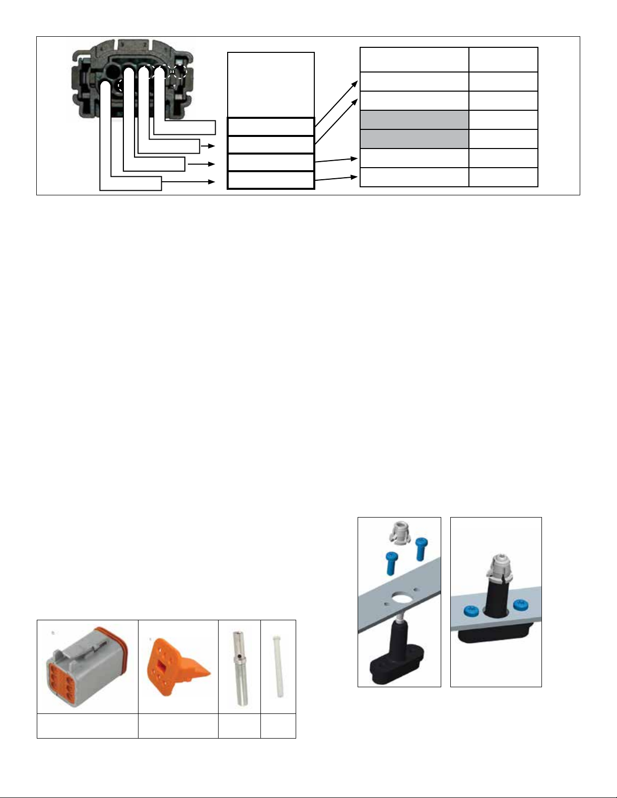
Kit Contents
Description Qty
Bendix®FLR20™Reman Radar . . . . . . . . . . 1
Adjusters/Screws. . . . . . . . . . . . . . . . . . 1
Bracket . . . . . . . . . . . . . . . . . . . . . . . 1
Harness Adapter . . . . . . . . . . . . . . . . . 1
Deutsch Connector Mating Kit . . . . . . . . . . 1
Upgrade Tag (BW1829) . . . . . . . . . . . . . . 1

2
Gain access to the radar; where necessary, remove
the bumper from the vehicle by following the vehicle
manufacturer's instructions.
Remove the Bendix®FLR10™Radar
1. Disconnect the wire harness from the Bendix®FLR10™
radar. Protect the connector and harness from damage.
2. Typically two (2) bolts are used to attach the bracket to
the vehicle. Remove and retain the bolts from the Radar
Assembly. (Inspect the bolts; replace corroded/damaged
bolts as necessary, using OEM-approved hardware.)
3. Remove the old radar assembly from the bracket and
save for core return.
Inspection
4. Inspect and clean all surfaces of the cross-member.
Any damage found that would affect the installation of
the new radar and bracket should be addressed before
continuing with the installation.
Preparing the Harness
5. See Figure 2. Record the wire colors used by the OEM.
for the locations of the existing speciality vehicle wire
harness in the spaces provided in Figure 2
6. Cut the existing wire harness 4 inches, or less, from the
connector. After verifying that the wire colors recorded
in step 5 above are correct, discard the connector.
7. Carefully review the Deutsch connector manufacturer’s
instructions for stripping and crimping the wire into the
new connector before proceeding.
Deutsch ST06-6S Connector Wedge Used with
Connector
Socket
Part Plug
FIGURE 3 - CONNECTOR COMPONENTS
Follow the manufacturer's directions in lieu of the
recommendations supplied here:
(a) Strip all four wires 0.250 to 0.312 inch.
(b) Crimp the Deutsch socket part [0462-201-16141] on
each of the exposed wires. See Figure 4.
(c) Insert color coded wire/terminal from the truck side
(from step 5) into cavity from the rear, following the wir-
ing colors recorded in Step 5. For the two locations not
being used, insert the [0413-217-1605] white sealing
plugs.
Listen for the audible (and tactile) “click”, when the socket
seats correctly in the plug.
8. Insert the Deutsch W6S™locking wedge into the front of
the connector. See Figure 3.
9. Plug the assembled connector into the harness adapter
supplied.
Prepare the Bendix®FLR20™Radar and Bracket
10. Insert the three (3) new adjuster assemblies into the
bracket.
FIGURE 4 - RADAR SENSOR ADJUSTERS INSTALLATION
11. Insert the six (6) adjuster mounting screws into the
assembly. Using a Torx T20 driver, start every screw
into the assembly, then tighten them all to 30 in-lbs.
Record the wire
colors used
for the original
radar system
here Ô
Cavity 1: Ground
Cavity 2: CAN1_Hi
Cavity 8: Power
Cavity 3: CAN1_Lo
Function DT06-6S
Cavity Designation
Ground 1
CAN1_Hi 2
Not Used — Use Plug Supplied 3
Not Used — Use Plug Supplied 4
CAN1_Lo 5
Power 6
FIGURE 2 - EXISTING WIRE DESIGNATIONS AND THE DT06-6S CAVITIES TO USE IN THE NEW CONNECTOR

3
Bracket Varies
Note: Most Brackets
Have Specific Openings
for Routing the Harness
FIGURE 5 - RADAR SENSOR INSTALLATION (EXPLODED
VIEW)
12. See Figure 5. With the connector pointing to the
passenger side of the vehicle when installed, align the
holes in the radar sensor with the adjusters. Install the
new radar onto the adjusters by pressing, by hand, with
moderate force, on the front surface of the radar. Verify
that all three clips at the top of the adjusters have fully
engaged into the radar.
Install the Harness
13. Insert the connector into the Bendix®FLR20™radar.
14. Slide the orange Connector Position Assurance (CPA) tab
to the right, making sure the connector is fully engaged.
15.Routetheharnessthroughthebackofthebracket,rmly
securing as necessary.
16. Install the Radar Assembly onto the vehicle by using
two (2) bolts removed during disassembly. Torque to
vehicleOEspecications.
17. ALIGN THE RADAR, per the Appendix on pages 4-6
or refer to Bendix Service Data Sheet, SD-61-4960,
available for download or order from www.bendix.com.
Remove the steel clip or plate before returning the
vehicle to service. When removing stretch-release
adhesive strips, be sure to pull directly down on the tab
provided and clean any adhesive residue that may be
present on the sensor.
18. For installations where the bracket has a cover, insert
the supplied mounting screws through their respective
washers. These are then inserted through the cover
and retained by nylon washers on the other side. See
Figure 6. Typically the radar will be aligned before the
cover is installed.
Mounting Screw
Nylon
Retaining
Washer
Washer
FIGURE 6 - NYLON WASHER INSTALLATION (WHERE
NEEDED)
Using a Phillips screwdriver, attach the cover to the
bracket using the two screws.
19. Re-install the vehicle's bumper if it was necessary
to remove it for this installation, following the OEM's
approved practices. Check for radar clearance as shown
intheServiceDataSheet.Somebumpermodication
may be necessary.
20. Return the radar sensor removed from the vehicle,
for core return credit using the Bendix Upgrade Tag
(BW1829) supplied in the kit. The radar must be carefully
packaged using suitable materials in a separate container
from other core returns.
Bendix Technical Assistance Team
For direct telephone technical support, call the Bendix Tech
Team at:
1-800-AIR-BRAKE (1-800-247-2725), option 2. Tech Team
members are available Monday through Friday, 8:00 a.m. to
6:00 p.m. ET.
Please have the following information ready when you
contact the Bendix Tech Team: Bendix product model
number;partnumberandconguration;vehiclemakeand
model.

4
Appendix
Bendix®FLR20™Radar Alignment
A1 LATERAL ALIGNMENT USING THE BENDIX®ALIGNMENT TOOL
This is the method to use for lateral alignment when a radar and/or bracket is replaced.
Tools needed: Bendix alignment kit, steel clip or plate, Torx T-20 screwdriver and a tape measure.
• One of the Bendix Alignment Tools part no: K065284 and K096579 — available from Bendix parts outlets —are used.
The alignment procedure also requires a steel clip, part number K073087, [or steel plate, (K105222) along with stretch-
release adhesive tape].
ALIGNMENT TOOLS AVAILABLE
Alignment Tool
with Laser
Guide
K065284
Magnetic
Feet
(3)
Alignment Tool Mounting Surface
A. Steel Clip
(design may vary) B. Steel Plate
Mounts by sliding over the
sensor
Mounts using stretch-release
adhesive tape
K096579
Shorter
Bar
A1 Parkthevehicleonaleveloor.Airsuspensionsmustbechargedandstable.Installthesteelclipbyslidingit
over the sensor, or install the steel plate to the front of the sensor using stretch-release adhesive tape.
A2 Attach the alignment tool onto the clip or plate using its magnetic feet. Inspect to make sure that the alignment
tool is approximately horizontal, width-wise.
A3 Activatethelateralalignmentlaserlight“on”switch.Placethetoolintopositionfortherstmeasurement.(The
tool will be reversed when the second measurement is made.)
APPENDIX - RADAR ALIGNMENT USING BENDIX®ALIGNMENT CLIP AND TOOL

5
Appendix
Bendix®FLR20™Radar Alignment
LATERAL ALIGNMENT USING THE BENDIX®ALIGNMENT TOOL(CONTINUED)
A4 Locate symmetrical points on the front of the vehicle that are at least 12 inches from the vehicle’s center line (such as
the tow hooks). Using a ruler or tape measure, record the distance from each side to the laser light line.
LATERAL ALIGNMENT LEFT MEASUREMENT
NOTE: The technician must be careful during the laser positioning process to double-check the values measured on each
side of the truck. Be sure to check back and forth for each side of the radar sensor several times to ensure accuracy.
A5 Repeat the process for the opposite side, reversing the tool, so that the laser light points to the other side of the
vehicle.
Lateral Alignment
Laser
Laser
Light Beam
The Whole
Tool is
Reversed for
the Second
Measurement
A6 Compare the left and right distance measurements. A properly aligned radar sensor will have the same measurement
from each side. If these two dimensions are within 1/8” (3 mm), no alignment is necessary and the technician can
go to Step A10 to check the vertical alignment. If an adjustment is needed, follow the instructions in A7-9.

6
Appendix
Bendix®FLR20™Radar Alignment
LATERAL ALIGNMENT USING THE BENDIX®ALIGNMENT TOOL(CONTINUED)
NOTE: Complete these steps only if a lateral adjustment is necessary.
A7 With the Bendix alignment tool still in place, use the Torx T-20 screwdriver to turn by hand the driver-side stand-off
adjustment screw until the desired alignment is reached.
Use a Torx T-20 screwdriver here to
adjust for the lateral alignment
IMPORTANT:
Do not adjust
this stand-off!!
A8 Re-measure the distances from symmetrical points located at least 12” from the center line of the vehicle. Reverse
the tool for each measurement, until the values are the same [within 1/8” (3 mm)].
A9 After the lateral alignment procedure is complete, if there is an active misalignment DTC (codes 55, 56, or 57), use
the instructions in Bendix Service Data Sheet, SD-61-4960 (available from www.bendix.com) to clear the Bendix®
Wingman®Advanced™system's Diagnostic Trouble Code (DTC) using the procedure in Section 4.4: Clearing
Diagnostic Trouble Codes (DTCs) and reset the alignment value by connecting the vehicle to a PC with Bendix®
ACom®Diagnostics software and follow steps B4.4-20 to reset the alignment value. (Also, see Appendix H
of the Service Data Sheet.)
A10 IMPORTANT: Before returning the vehicle to service, check the vertical alignment.
A11 [The steel clip, or plate, and alignment tool should already be in place. See A1-2.]
A12 Calibrate (or “zero”) the inclinometer on a horizontal section of the frame rail. Follow the manufacturer’s instructions
(typically digital inclinometers have a “SET” button for this purpose).
Calibrate (or “zero”) the Digital Inclinometer on a
Cab Frame Rail in the direction that the vehicle
travels.
Place the calibrated digital inclinometer onto the
surface of the tool, so that the tool is in the
same direction as it was on the rail. Verify
that the display shows 0° (± 1.5°) from vertical.
NOTE: Complete these steps only if a vertical adjustment is necessary.
A13 With the Bendix alignment tool still in place, use the screwdriver to turn
by hand the top-left adjustment stand-off. See the Figure on the right.
During the adjustment, observe the digital display on the inclinometer
and turn the vertical alignment screw clockwise or counterclockwise
depending on the vertical direction (up or down) needed, until the
reading is near zero degrees.
A14 The radar is aligned vertically when the display is near zero (0°).
Note: The alignment process shown here is for Bendix alignment
brackets. For other brackets, similar alignment steps will be needed;
consult the vehicle manual for full instructions.
Use a Torx T-20 screwdriver here to
adjust for the vertical alignment
IMPORTANT:
Do not adjust
this stand-off!!
NOTE: The alignment process is complete after the vertical alignment has been checked (and adjusted, if
necessary), and the steel clip or plate is removed. You do not need to test-drive the vehicle.

7
Appendix
Bendix®FLR20™Radar Alignment
Remove the steel clip or plate before returning the vehicle to service. When removing the stretch-release adhesive
strips, be sure to pull directly down on the tab provided and clean any adhesive residue that may be present on
the sensor.
Call the Bendix Tech Team at 1-800-AIR-BRAKE (1-800-247-2725), option 2, for troubleshooting assistance.

8S-1627 © 2014 Bendix Commercial Vehicle Systems LLC, a member of the Knorr-Bremse Group. 08/14. All Rights Reserved.
Log-on and Learn from the Best
On-line training that's available when you are 24/7/365.
Visit www.brake-school.com.
Other manuals for Wingman FLR20
1
This manual suits for next models
1
Table of contents
Other BENDIX Automobile Accessories manuals

BENDIX
BENDIX AUTOVUE FLC-20 Mounting instructions

BENDIX
BENDIX TABS-6 TRAILER ABS MODULE Mounting instructions

BENDIX
BENDIX Bendix Wingman ACB Mounting instructions

BENDIX
BENDIX ADB22X-V Mounting instructions

BENDIX
BENDIX Bendix Wingman Advanced User manual

BENDIX
BENDIX VORAD VS-400 User manual

BENDIX
BENDIX Sheppard Mounting instructions

BENDIX
BENDIX TC-2 User manual

BENDIX
BENDIX Gen. 4 ABS ECU User manual

BENDIX
BENDIX BlindSpotter BW2860 Configuration guide