BENDIX TLV-9000 Mounting instructions

1
21
Suspension
Bag Delivery
23
Lift Bag
Delivery
®
SD-03-3430
DESCRIPTION
The TLV-9000™lift axle valve is used on trailers or
vehicles with Bendix®TA BS - 6™Advanced single- and
multi-channel systems to control the lift axle(s) raising
and lowering automatically. This allows the vehicle to
use extra axle(s) when required for payload distribution
and to be unloaded to save on wheel-end wear and fuel
economy.
TLV-9000™ Lift Axle Valve
Figure 1 – TLV-9000™Lift Axle Valve
Port / Function Embossed ID Port Size Quantity
Lift Bag - Supply 1 3/8" 1
Suspension Bag - Supply 11 3/8" 1
Lift Bags - Delivery 23 3/8" 2
Suspension Bags - Delivery 21 3/8" 2
Exhaust - - 1
Connector: DIN72585-A1-2.1
Weight: 1.2 lbs.
Operating Pressure: 145 psi Max
Operating Temperature: -40° – 200°F
The lift axle contains a solenoid for electronic switch
lifting and lowering actuation. The lift axle valve contains
3/8” push-to-connect fittings for easy installation.
Refer to Table 1 for port identication and other valve
characteristics.
Table 1 – TLV-9000 Lift Axle Valve Characteristics
12 VDC Electrical
Twist-Lock
Connector
(2-Pin Bayonet
Style)
11
Suspension Bag
Supply
(From Height
Control Valve)
1
Lift Bag Supply
(From Reservoir)
Exhaust - Cannot
Be Pointed Down
(Toward the Road)
when Installed
Mounting
Holes

2
OPERATION
The TLV-9000™lift axle valve is a 5/2 way (5 ports and
2 ow positions) electro-pneumatic valve that directionally
controls the raising and lowering of the lift axle via an
electronic signal from the Bendix® trailer ABS/TRSP
(Antilock Braking System /Trailer Roll Stability Program)
Electronic Control Unit (ECU) based on pressure sensing.
The valve allows the lift axle to be raised and lowered via
a 12 VDC command using a standard wiring harness to
either exhaust the suspension bags and ll the lift bags or
exhaust the lift bags and ll the suspension bags.
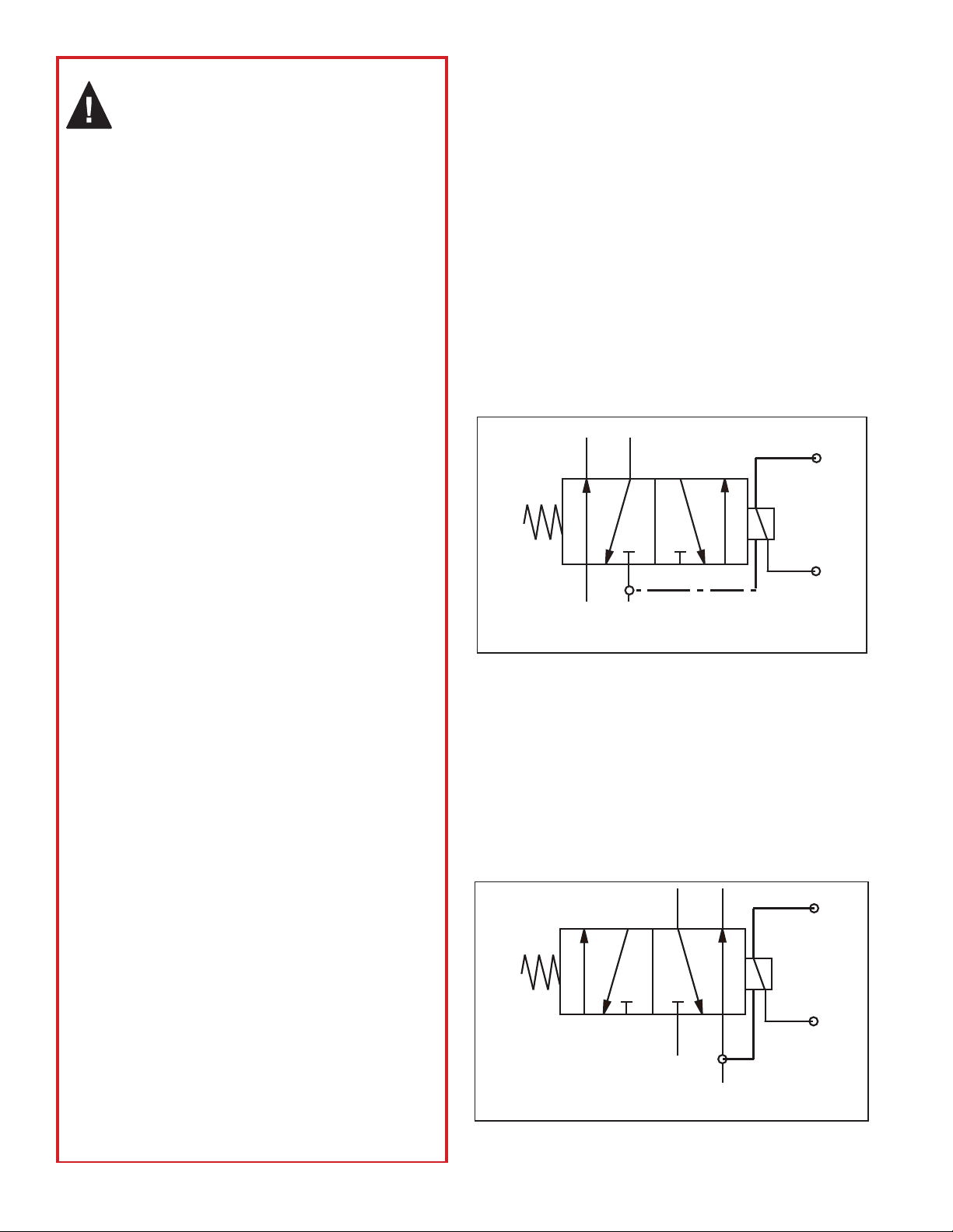
The valve, while in a non-voltage applied state, delivers
supply pressure to the suspension bags only, providing a
ground position for the lift axle. When the lift axle is in the
down position, an internal piston prevents pressure from
being applied to the lift bags with its circuit open to exhaust.
Refer to Figures 2 and 5.
In the applied voltage state, the valve’s solenoid opens and
allows air pressure to compress the internal piston spring
changing the operation of the valve. During this function,
the piston redirects the pressure from the suspension bags
and now delivers pressure to the lift bags. The suspension
bag circuit opens to exhaust and the lift axle is now in the
raised position. Refer to Figures 3 and 6.
GENERAL SAFETY GUIDELINES
WARNING! PLEASE READ AND
FOLLOW THESE INSTRUCTIONS
TO AVOID PERSONAL INJURY OR DEATH:
When working on or around a vehicle, the following
guidelines should be observed AT ALL TIMES:
▲Park the vehicle on a level surface, apply the parking
brakes and always block the wheels. Always wear personal
protection equipment.
▲Stop the engine and remove the ignition key when working
under or around the vehicle. When working in the engine
compartment, the engine should be shut off and the ignition
key should be removed. Where circumstances require that
the engine be in operation, EXTREME CAUTION should be
used to prevent personal injury resulting from contact with
moving, rotating, leaking, heated or electrically-charged
components.
▲Do not attempt to install, remove, disassemble or
assemble a component until you have read, and thoroughly
understand, the recommended procedures. Use only the
proper tools and observe all precautions pertaining to use
of those tools.
▲If the work is being performed on the vehicle’s air brake
system, or any auxiliary pressurized air systems, make
certain to drain the air pressure from all reservoirs before
beginning ANY work on the vehicle. If the vehicle is
equipped with a Bendix®AD-IS®air dryer system, a Bendix®
DRM™dryer reservoir module, or a Bendix® AD-9si®air
dryer, be sure to drain the purge reservoir.
▲
Following the vehicle manufacturer’s recommended
procedures, deactivate the electrical system in a manner
that safely removes all electrical power from the vehicle
.
▲Never exceed manufacturer’s recommended pressures.
▲Never connect or disconnect a hose or line containing
pressure; it may whip and/or cause hazardous airborne
dust and dirt particles. Wear eye protection. Slowly open
connections with care, and verify that no pressure is
present. Never remove a component or plug unless you are
certain all system pressure has been depleted.
▲Use only genuine Bendix®brand replacement parts,
components and kits. Replacement hardware, tubing, hose,
fi ttings, wiring, etc. must be of equivalent size, type and
strength as original equipment and be designed specifi cally
for such applications and systems.
▲Components with stripped threads or damaged parts should
be replaced rather than repaired. Do not attempt repairs
requiring machining or welding unless specifi cally stated
and approved by the vehicle and component manufacturer.
▲Prior to returning the vehicle to service, make certain all
components and systems are restored to their proper
operating condition.
▲For vehicles with Automatic Traction Control (ATC), the ATC
function must be disabled (ATC indicator lamp should be
ON) prior to performing any vehicle maintenance where
one or more wheels on a drive axle are lifted off the ground
and moving.
▲The power MUST be temporarily disconnected from the
radar sensor whenever any tests USING A DYNAMOMETER
are conducted on a vehicle equipped with a Bendix®
Wingman®system.
▲You should consult the vehicle manufacturer's operating
and service manuals, and any related literature, in
conjunction with the Guidelines above.
Figure 3 – Lift Bag Delivery Position (Lift Axle in Raised
State)
Power ON
(Solenoid is Energized)
4
1311
21 23
4
1311
21 23
Figure 2 – Suspension Delivery Position (Lift Axle Down
and in Normal State)
Power OFF
(Solenoid is in Ground State)

3
Lift Axle
Lift Axle
Figure 4 – Typical Trailer Air Brake System with a TLV-9000™Lift Axle Valve
FRONT
Trailer ABS
Module
Relay
Valve

4
Bendix®TR-3™
Lift Axle Service
Shut-Off Valve
To Lift Axle
Service
Relay Valve
Control Port
Trailer
ABS
Module
Suspension Bag
Lift Bag
Lift Axle
Lift Axle
Figure 5 – Normal Operation
Figure 6 – Lift Operation
Suspension Bags Filled, Lift Bags Exhausted
TLV-9000™Valve Lifts the Axle by Exhausting the Suspension Bags & Filling the Lift Bags
TABS-6
ADVANCED
42
(LOAD)
Bendix®TR-3™
Lift Axle Service
Shut-Off Valve
To Lift Axle
Service
Relay Valve
Control Port
Trailer
ABS
Module
Suspension Bag
Lift Bag
Lift Axle
Lift Axle

5
Figure 7 – Return to Normal Operation
TLV-9000™Valve Fills the Suspension Bags & Exhausts the Lift Bags
MANUAL OVERRIDE FEATURE
The TLV-9000™lift axle valve is controlled by the Bendix®
trailer ABS/TRSP ECU, via a wiring harness, to provide lift
axle operation based on load sensing logic programmed
into the ECU. During normal operation the driver does not
control the lift axle. For drop-axle control Bendix offers a
manual override harness available from any authorized
service parts outlet. Refer to Figure 8.
Figure 8 – Wire Harnesses
Connects to
the ECU
Connects to the
Pressure Switch
or the Manual
Override Harness
If Used
Bayonet Connector
(Connects to the
Bendix®TLV-9000™
Lift Axle Valve)
Bendix®TA BS - 6™Advanced Lift Axle Control Harness
A
Connects to
the Lift Axle
Harness "A"
Connects to
the Pressure
Switch
Bendix TABS-6 Advanced Override Harness
Connects to
the Toggle
Switch
The override harness can simply be connected to the
existing lift axle wiring harness to manually complete the
electrical ground loop circuit. This function allows the
driver to drop the lift axle when desired (as opposed to
load sensing) and remain on the ground as long as the
switch is activated. When the switch is deactivated, the
axle will only raise if the trailer payload is under the weight
requirement (normal load sensing operation). The switch
is provided by trailer OEM only.
Bendix®TR-3™
Lift Axle Service
Shut-Off Valve
To Lift Axle
Service
Relay Valve
Control Port
Trailer
ABS
Module
Suspension Bag
Lift Bag
Lift Axle
Lift Axle

6
or 1500 operating hours, whichever comes first, for
proper operation. Should the TLV-9000 valve not meet the
elements of the operational tests noted in this document,
further investigation and replacement of the valve may be
required.
SERVICE
The TLV-9000 lift axle valve sold in North America is
non-serviceable. See your authorized Bendix service parts
outlet for a replacement valve or wiring harness, if needed.
OPERATIONAL AND LEAKAGE TESTS
There are two methods of performing operational and
leakage tests for the TLV-9000 lift axle valve. The rst
method can be performed using Bendix®ACom®diagnostic
software (which can be downloaded from bendix.com) and
the second can be completed by manually testing the valve.
1 - TESTING WITH ACOM DIAGNOSTIC SOFTWARE
ACom diagnostic software (version 6.17.4.3 or higher) is an
RP-1210 compliant, PC-based diagnostic software pro-
gram that provides the highest level of diagnostic support
for the air brake systems that use the Bendix® TABS-6
Advanced MC™module. With Bendix ACom diagnostic
software, maintenance personnel can:
• Obtain DTC information (both active and inactive DTCs)
• Retrieve event history
• Clear inactive DTCs and event history
• Verify ECU conguration
• Perform system and component tests
• Read/write customer information in the scratch pad
• Save and print information
• Receive troubleshooting assistance
Connect the computer’s serial or parallel port to the
vehicle’s diagnostic connector through an RP-1210
compliant communications device.
Figure 9 – Laptop Computer with Bendix®ACom®
Diagnostic Software
USB Cable
Noregon
Adapter
J2497 (PLC)
or J1939
Lap Top
Computer
Figure 10 – Bendix ACom Start Screen
Press
Start / Next
SYSTEM DIAGRAM
Figure 4 shows a trailer air-brake schematic of a single lift
axle controlled by the TLV-9000™lift axle valve. The lift
axle valve operation is electronically controlled with Bendix®
TABS-6™Advanced by using a load (pressure) sensor to
indicate payload weight and a leveling valve to control the
suspension height.
The valve has two air supply (inlet) ports and four air
delivery (outlet) ports. One supply port is the suspension
supply (Port 11) and the second is the lift supply (Port 1).
The valve has two ports for each delivery; Ports 21 deliver
to each suspension bag and Ports 23 deliver to each lift
bag. The exhaust port is located on the side of the valve
between the two supply ports and allows the lift bags and
suspension bags to exhaust. Refer to Table 1 and Figures
1 and 5.
INSTALLATION REQUIREMENT
For proper TLV-9000 valve and lift axle performance, the
recommended tubing size from the reservoir pressure
protection valve to the S1 supply port shall be 3/8" O.D.
(1/4” I.D.) copper or non-metallic per SAE J844, and
maintained as such without reductions. Any restrictions
in the supply line (including ttings) may delay or prevent
the valve from operating as designed.
PREVENTIVE MAINTENANCE
Important: Review the Bendix Warranty Policy before
performing any intrusive maintenance procedures. A
warranty may be voided if intrusive maintenance is
performed during the warranty period.
No two vehicles operate under identical conditions; as
a result, maintenance intervals may vary. Experience is
a valuable guide in determining the best maintenance
interval for air supply system components. At a minimum,
the TLV-9000 valve should be inspected every 6 months

7
Figure 11 – Testing Aux Output with the Switch On
Figure 13 – Test Complete
Figure 12 – Testing Aux Output with the Switch Off
Launch the Bendix®ACom®diagnostic software program
and select component test, LAC1 Test on Congured AUX
I/O, to perform functionality/operational checks or diagnose
lift axle issues. For general override, select LL_ALL Test
on Congured AUX I/O. Refer to Figure 10.
This test will conrm if power is applied to the source.
If the output switch is not on, disconnect the electrical
connector from the lift axle valve and manually
apply 12 VDC to determine if the problem indicates
electrical wiring or the TLV-9000™lift axle valve.
For troubleshooting information refer to the Bendix®
TABS-6™Advanced Service Data Sheet referenced in
this document. Refer to Figure 11.
The next test will conrm if the power output is turned off
at the source. Refer to Figure 12.
A check mark next to the test description indicates a
successful test completion. Refer to Figure 13.
2 - MANUAL (NON-SOFTWARE) METHOD OF TESTING
VALVE OPERATION
1. Block the vehicles wheels and fully charge the tractor
and trailer air system. The trailer must not be loaded
for this test.
2. Apply the vehicle parking brakes.
3. With the wiring harness disconnected from the
TLV-9000 lift axle valve, disconnect both air lines
from the lift bag delivery ports (Ports 23) and install
test plugs into the ttings. Apply a soap solution around
the opening of the exhaust port and check for leakage.
Leakage must not exceed a one (1) inch bubble in less
than ve (5) seconds around the exhaust seal.
4. Remove the test plugs and reconnect both air lines back
to the lift bag delivery ports (Ports 23). Apply power
(12 VDC) via a separate power supply to the TLV-9000
valve. The lift axle must rise to the desired position.
5. With the lift axle in the raised position, disconnect both
air lines from the suspension bag delivery ports (Ports
21) and install test plugs into the ttings. Apply a soap
solution around the opening of the exhaust port and
check for leakage. Leakage must not exceed a one
(1) inch bubble in less than ve (5) seconds around the
exhaust seal.
6. Remove the test plugs and reconnect both lines back
to the suspension bag delivery ports (Ports 21). Turn
off the power to the TLV-9000 lift axle valve. The lift
axle should return to its original position.
If the valve does not function as described; or if leakage is
excessive, replace the valve.

8
TROUBLESHOOTING
For situations with the TLV-9000™lift axle valve that result
in the lift axle stuck in either the raised or lowered position,
please refer to the following Bendix Service Data sheets
available at bendix.com:
SD-13-47671 (Bendix® TABS-6™Advanced Single
Channel) - Sections G and H
SD-13-47672 (TABS-6 Advanced Multi Channel) -
Sections H and J
REMOVAL
1. Identify and mark or label all air lines and their
connections to the TLV-9000 lift axle valve. Then
disconnect the air lines and the electrical connector.
2. Remove the TLV-9000 valve from the vehicle. Retain
the mounting hardware.
INSTALLATION
1. Install the TLV-9000 valve on the vehicle frame using
the two M8 x 60 screws that were retained in the
removal process. Torque to 19 ft-lbs.
2. Reconnect all air lines to the valve using the
identication made during removal.
3. Test all air fittings for leakage. Also, perform
OPERATIONALAND LEAKAGE TESTS before placing
the vehicle back into service.
SD-03-3430 Rev. 001 © 2019 Bendix Commercial Vehicle Systems LLC, a member of the Knorr-Bremse Group • 05/19 • All Rights Reserved
Log-on and Learn from the Best
On-line training that's available when you are 24/7/365.
Visit brake-school.com.
Table of contents
Other BENDIX Automobile Accessories manuals

BENDIX
BENDIX Bendix Wingman Advanced User manual

BENDIX
BENDIX Intellipark User manual

BENDIX
BENDIX Bendix Wingman ACB Mounting instructions

BENDIX
BENDIX SmarTire User manual

BENDIX
BENDIX VORAD VS-400 User manual

BENDIX
BENDIX TABS-6 TRAILER ABS MODULE Mounting instructions

BENDIX
BENDIX ADB22X-V Mounting instructions

BENDIX
BENDIX BlindSpotter BW2860 Configuration guide

BENDIX
BENDIX VORAD VS-400 Installation and operation manual

BENDIX
BENDIX ACTIVE STEERING SYSTEM User manual