2
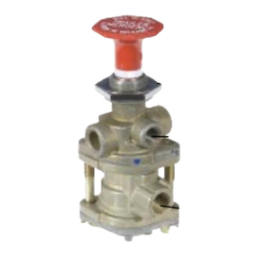
PP-1 20,30,40
or 60 psi
PP-2 40 psi
PP-5 40 psi 18 psi
RD-3 Must be held
manually
PP-8 Will remain in
either position
4. Removetheinlet-exhaust valve (4),andpiston (5).
5. Removeo-rings (6 & 7) from piston.
OPERATING AND LEAKAGE TESTS
PP-1™, PP-8™, RD-3™VALVE
1. An accurate test gauge should be tee’d into the supply
lineanda means ofcontrollingthe supply pressurepro-
vided. Apply a 120 psi air source to the supply port. A
small volume reservoir (e.g. 90 cu. in.) with a gauge
should be connected to the delivery port.
2. With 120 psi supply pressure, and the button pulled out
(exhaust position), leakage at the exhaust port should
not exceed a 1" bubble in 5 seconds; at the plunger
stema1"bubblein5 seconds. There should benoleak-
agebetweenupper and lower body.
3. Push the button in (applied position). Leakage at the ex-
haustport should not exceed a 1" bubble in 3seconds;at
the plunger a 1" bubble in 3 seconds. (The RD-3™valve
will have to be manually held in this position.)
4. Reduce the supply pressure. At a pressure from 60 to
20psidependingonthespringinstalledthebuttonshould
pop out automatically, exhausting the delivery volume.
(This does not apply to the RD-3™, PP-8™or some
PP-1™valve’s).
PP-5™VALVE
1. Proceedas for PP-1™valvethrough Step3.
2. Connect a modulated source of air pressure to the pilot
air inlet. With the button pushed in (applied position)
with125psi supply pressureanda gradually increasing
pressure applied at the pilot air port the valve should
move to the release position with a pilot pressure of not
more than 18 psi. Leakage in this mode should not
exceed a 1" bubble in 3 seconds at the exhaust port
and a 1" bubble in 5 seconds at the plunger stem.
PP-2™VALVE
1. Proceedas for PP-1™valvethrough Step1.
2. With the button pulled out (exhaust position), leakage
atthebrake valve portorat the plungerstemshould not
exceed a 1" bubble in 5 seconds.
3. Push the button in. Supply pressure should be present
in the delivery volume. Leakage at the exhaust port or
aroundtheplunger stem shouldnot exceed a1" bubble
in 5 seconds.
4. Pull the button out and apply supply pressure at the
brake valve port. Supply pressure should be present in
the delivery volume and leakage at the exhaust port
should not exceed a 1" bubble in 5 seconds.
Note: Ifanyoftheabovepush-pullvalvesdo not function as
described or if leakage is excessive, it is recommended
they be returned to our nearest authorized distributor for a
factoryrebuiltornew valve.
REMOVAL
Block and/or hold the vehicle by a means other than air
brakesanddrain all reservoirs.
1. Drivethebuttonroll-pinoutwithapunchandremovethe
button.
2. Markeachair supply lineandits port foreasyreinstalla-
tion,then disconnectthem. Remove the valve from the
panelby removing the panel mountingnut.
INSTALLING
1. Install valve in panel, securing with the panel mounting
nut.
2. Reconnecttheairlinesusingmarksmadeduringremoval
as a guide.
3. Installtheoperatingbutton.Secure the operating button
by installing the button roll pin.
DISASSEMBLY: PP-1™, PP-8™AND RD-3™
VALVES
1. Remove the two cap screws (3) which retain the lower
coverandremovecover. Remove the sealingring(4).
2. Insertasmall punch through therollpin hole inthestem
and remove the lock nut (5).
3. Removeinlet-exhaustvalve(6)andplunger(7)andspring
(8)(if any).
4. Removeo-ring(9)fromplunger.
DISASSEMBLY: PP-5™VALVE
1. Performsameoperations as forPP-1™valve.
2. Remove inlet seal (10) in Figure 4 from lower cover.
Removethe ringdiaphragm (4)from theinlet seat.
3. Removepiston(11)Figure 4 ando-ring (2).
DISASSEMBLY: PP-2™VALVE
1. Insertasmallpunchthroughtherollpinholeintheplunger
and remove the lock nut (1) from the plunger.
2. Withdraw the plunger and remove the spring (9) and
o-ring(8).
3. Remove the two machine screws (2) and remove the
lowercover(3).
AUTOMATIC MOMENTARY PILOT TRIP NON-
EXHAUST APPLY FEATURE AUTOMATIC
