manuals.online logo
Brands
  1. Home
  2. •
  3. Brands
  4. •
  5. BENDIX
  6. •
  7. Control Unit
  8. •
  9. BENDIX QRN-2 QUICK RELEASE VALVE User manual

BENDIX QRN-2 QUICK RELEASE VALVE User manual

®
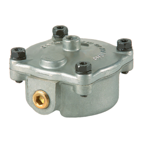
FIGURE 1 - QRN-2™QUICK RELEASE VALVE
EXHAUST
COVER
EXHAUST
DELIVERY
SUPPLY DELIVERY
SUPPLY
BODY
BODY
DELIVERY
PIECE
NUMBER, DATE
CODE, AND
T.M.C.
IDENTIFICATIONS
STAMPED
HERE
1.50"
DESCRIPTION
The Bendix®QRN-2™quick release valve is a lightweight,
nonmetallic quick release valve. It is designed to “speed
up”thereleaseofairfromthedevicesitisattachedto. Inits
standardconfigurationthevalveisdesigned todeliverwithin
1psiof control pressure. However,for specialapplications
thevalveis available with zerohysteresis.
Port Embossed I.D.
Supply SUP 1
Delivery DEL2
Exhaust EXH3
FRONT AXLE
BRAKE
CHAMBER
FIGURE 3 - PARTIAL SYSTEM SCHEMATIC WITH QRN-2™
QUICK RELEASE VALVE
FIGURE 2 - QRN-2™QUICK RELEASE VALVE SECTIONAL
VIEW
DUAL BRAKE
VALVE
QRN-2™
VALVE
SUPPLY BRAKE VALVE
SECONDARY
CIRCUIT
DELIVERY
DELIVERY
DELIVERY
SUPPLY
RESERVOIR
SECONDARY
CIRCUIT
RESERVOIR
Supply port: 1/2"-14 P.T. or 3/8"-18 P.T.
Deliveryports: 3/8"-18P.T.
Weight: .3 lb.
Material: Moldedblack reinforced nylon 6
Operatingpressure: 150 psi maximum
Operating temperature: -40° to 180° F
Bendix®QRN-2™Quick Release Valve
SD-03-907
EXHAUST
DELIVERY DELIVERY
SUPPLY
DIAPHRAGM
Figure1 shows theQRN-2™valvewithitsportdesignations,
datecode,piecenumberandT.M.C.identifications. Figure
2isasectionalview. Notethat the standard QRN-2™valve,
which has a 1 psi maximum differential, does notinclude a
differentialspring. Figure 3 showsapartialairbrake system
schematic with a QRN-2™valve. Receiving its signal from
thesecondarybrakecircuit, the QRN-2™valve is controlling
thefront axle brake chambers.
OPERATION
APPLY
As shown in Figure 4, when air pressure enters the supply
port, it causes the center portion of the diaphragm to seal
theexhaust. Supplyairpressuresimultaneouslyforcesthe
edges of the diaphragm away from the sealing lip in the
body, allowing air to flow out the delivery ports. Delivery
pressure will be within 1 psi of supply pressure for the
standardQRN-2™valve.
BALANCE
Figure 5 shows the QRN-2™valve balanced mode. When
airpressurebeneathdiaphragmisapproximately 1 psi less
thanair pressure above the diaphragm, the outer edges of
the diaphragm seal against the body’s sealing lip. The
exhaustremains sealedbecauseairpressurebears against
thecenter portion of thediaphragm from oneside only.
RELEASE
WhenairpressureisremovedfromtheQRN-2™valvesupply
port,the air pressureon the delivery side of the diaphragm
holds the outer edge of the diaphragm against the sealing
lipinthebodywhilesimultaneouslymovingthecenterportion
awayfrom the exhaustport. Airfromthedelivery portsflows
out the exhaust. When delivery air pressure is fully
exhausted, the diaphragm will return to its natural state,
withitsouteredges sealingthedeliveryanditscenterportion
sealing the exhaust.
WARNING! PLEASE READ AND FOLLOW
THESE INSTRUCTIONS TO AVOID
PERSONAL INJURYOR DEATH:
When working on or around a vehicle, the following
general precautions should be observed at all times.
1. Park the vehicle on a level surface, apply the
parking brakes, and always block the wheels.
Always wear safety glasses.
2. Stop the engine and remove ignition key when
working under or around the vehicle. When
working in the engine compartment, the engine
should be shut off and the ignition key should be
removed. Where circumstances require that the
enginebe in operation, EXTREME CAUTIONshould
be used to prevent personal injury resulting from
contact with moving, rotating, leaking, heated or
electrically charged components.
DELIVERY DELIVERY
DELIVERY
SEALED
SUPPLY
DIAPHRAGM
EXHAUST
EXHAUST
SEALED
DELIVERY
SUPPLY
DIAPHRAGM
EXHAUST
DELIVERY
FIGURE 4 - QRN-2™QUICK RELEASE VALVE APPLY
FIGURE 5 - QRN-2™QUICK RELEASE VALVE BALANCE
FIGURE 6 - QRN-2™QUICK RELEASE VALVE
RELEASE
DELIVERY
DELIVERY
SUPPLY
EXHAUST
DIAPHRAGM
3. Do not attempt to install, remove, disassemble or
assemble a component until you have read and
thoroughly understand the recommended
procedures. Useonly the proper tools and observe
all precautions pertaining to use of those tools.
4. If the work is being performed on the vehicle’s air
brake system, or any auxiliary pressurized air
systems,make certainto drain theair pressure from
all reservoirs before beginning ANY work on the
vehicle. If the vehicle is equipped with an AD-IS™
air dryer system or a dryer reservoir module, be
sure to drain the purge reservoir.
5. Following the vehicle manufacturer’s
recommendedprocedures, deactivate the electrical
system in a manner that safely removes all
electrical power from the vehicle.
6. Never exceed manufacturer’s recommended
pressures.
7. Never connect or disconnect a hose or line
containing pressure; it may whip. Never remove a
component or plug unless you are certain all
system pressure has been depleted.
8. Use only genuine Bendix®replacement parts,
components and kits. Replacement hardware,
tubing, hose, fittings, etc. must be of equivalent
size, type and strength as original equipment and
be designed specifically for such applications and
systems.
9. Components with stripped threads or damaged
parts should be replaced rather than repaired. Do
not attempt repairs requiring machining or welding
unless specifically stated and approved by the
vehicle and component manufacturer.
10. Prior to returning the vehicle to service, make
certainallcomponentsandsystemsarerestoredto
their proper operating condition.
PREVENTIVE MAINTENANCE
Important: Review the Bendix Warranty Policy before
performinganyintrusivemaintenanceprocedures.Awarranty
maybevoidedifintrusivemaintenanceisperformedduring
thewarrantyperiod.
No two vehicles operate under identical conditions, as a
result, maintenance intervals may vary. Experience is a
valuableguide in determining thebestmaintenanceinterval
forairbrakesystemcomponents.Ataminimum,theQRN-2™
valveshouldbeinspectedevery12monthsor3600operating
hours,whichever comes first,for proper operation.Should
theQRN-2™valvenotmeettheelementsof the operational
testsnotedinthisdocument,furtherinvestigationandservice
ofthevalvemayberequired.
SERVICE CHECKS
1. Remove any accumulated contaminants. Visually
inspectthe valve’s exterior forcracks, gouges, orother
physicaldamage. Replace the valveifphysicaldamage
is excessive.
2. Inspect all air lines connected to the valve for signs of
wearor physicaldamage. Repair/replaceas necessary.
3. Test air linefittingsforexcessive leakage and tighten or
replace as necessary.
OPERATIONAL AND LEAKAGE TESTS
1. Block the vehicle’s wheels and fully charge the air
system.
2. Applyandreleasetheservicebrakes several times and
check for prompt response of the brakes at the
appropriatewheels.
3. Withtheair system fully charged,apply a soap solution
to the QRN-2™valve exhaust port. Leakage of a 1"
bubble in 5 seconds is permissible.
4. Makeandholda full brake applicationandagainapplya
soapsolution to the QRN-2™valve exhaust. Leakageof
a 1" bubble in 3 seconds is permissible.
5. Withthebrakesstillapplied,applyasoapsolutionaround
thevalve where theexhaust cover meetsthe body. No
leakage at this point is permitted.
If the valve does not function as described, or if leakage is
excessive, replace it at any authorized parts outlet.
REMOVAL
1. Identify and mark or label all air lines and their
connectionstotheQRN-2™valve. Thendisconnectthe
air lines.
2. RemovetheQRN-2™valvefrom the vehicle. Retain the
mountinghardware.
INSTALLATION
1. Install the QRN-2™valve on the vehicle using the
mountinghardwaresavedduringremoval.
2. Reconnectallairlinestothevalveusing theidentification
madeduringremoval.
3. Test all air fittings for excessive leakage and tighten as
needed. NOTE: MAXIMUMTORQUEFORFITTINGS
IS10FT.LBS. PerformOPERATIONALANDLEAKAGE
TESTSbeforeplacingthe vehicle back into service.
NOTE: THERE ARE NO DISASSEMBLY/ASSEMBLY
PROCEDURES FOR THE QRN-2™VALVE. IT IS A
REPLACE ITEM. IF A VALVE DOES NOT MEET THE
OPERATIONALAND LEAKAGE TESTS, IT SHOULD BE
REPLACEDATANYAUTHORIZEDPARTSOUTLET.
BW1786 © 2004 Bendix Commercial Vehicle Systems LLC All rights reserved. 3/2004 Printed in U.S.A.

Other BENDIX Control Unit manuals

BENDIX SR-2 TRAILER SPRING BRAKE VALVE User manual

BENDIX

BENDIX SR-2 TRAILER SPRING BRAKE VALVE User manual

BENDIX QR-L INLINE QUICK RELEASE VALVE User manual

BENDIX

BENDIX QR-L INLINE QUICK RELEASE VALVE User manual

BENDIX ST-1 User manual

BENDIX

BENDIX ST-1 User manual

BENDIX R7 VALVE 3-04 SPANISH Instruction Manual

BENDIX

BENDIX R7 VALVE 3-04 SPANISH Instruction Manual

BENDIX EVERFLOW User manual

BENDIX

BENDIX EVERFLOW User manual

BENDIX E-7 DUAL BRAKE VALVE User manual

BENDIX

BENDIX E-7 DUAL BRAKE VALVE User manual

BENDIX TCS-9000 CONTROL BRAKE VALVE User manual

BENDIX

BENDIX TCS-9000 CONTROL BRAKE VALVE User manual

BENDIX R-8 RELAY VALVE User manual

BENDIX

BENDIX R-8 RELAY VALVE User manual

BENDIX AR-2 ANTILOCK RELAY VALVE User manual

BENDIX

BENDIX AR-2 ANTILOCK RELAY VALVE User manual

BENDIX TABS-6 TRAILER ABS MODULE Mounting instructions

BENDIX

BENDIX TABS-6 TRAILER ABS MODULE Mounting instructions

BENDIX RE-6 RELAY EMERGENCY VALVE User manual

BENDIX

BENDIX RE-6 RELAY EMERGENCY VALVE User manual

BENDIX E-10 DUAL BRAKE VALVES User manual

BENDIX

BENDIX E-10 DUAL BRAKE VALVES User manual

BENDIX TW-N TWO WAY CONTROL VALVE User manual

BENDIX

BENDIX TW-N TWO WAY CONTROL VALVE User manual

BENDIX ST-1 ST-3 SAFETY VALVE User manual

BENDIX

BENDIX ST-1 ST-3 SAFETY VALVE User manual

BENDIX RV-1 PRESSURE REDUCING VALVE User manual

BENDIX

BENDIX RV-1 PRESSURE REDUCING VALVE User manual

BENDIX R-8P PRESSURE EQUALIZING PILOTRELAY User guide

BENDIX

BENDIX R-8P PRESSURE EQUALIZING PILOTRELAY User guide

BENDIX TC-7 TRAILER CONTROL BRAKE VALVE User manual

BENDIX

BENDIX TC-7 TRAILER CONTROL BRAKE VALVE User manual

BENDIX SR-5 TRAILER SPRING BRK VALVE User manual

BENDIX

BENDIX SR-5 TRAILER SPRING BRK VALVE User manual

BENDIX DUAL RELAY VALVE User manual

BENDIX

BENDIX DUAL RELAY VALVE User manual

BENDIX PP-7 TRAILER SUPPLY VALVE User manual

BENDIX

BENDIX PP-7 TRAILER SUPPLY VALVE User manual

BENDIX SV-1 SYNCHRO-SV-3 TRAILER RELEASE User manual

BENDIX

BENDIX SV-1 SYNCHRO-SV-3 TRAILER RELEASE User manual

BENDIX R-7 MODULATING VALVE User manual

BENDIX

BENDIX R-7 MODULATING VALVE User manual

BENDIX TW-2 User manual

BENDIX

BENDIX TW-2 User manual

BENDIX TP-3 Mounting instructions

BENDIX

BENDIX TP-3 Mounting instructions

Popular Control Unit manuals by other brands

Bosch RTM 430 Repair instructions

Bosch

Bosch RTM 430 Repair instructions

Bardiani Valvole J-GIOTTO TOP Instruction, use and maintenance manual

Bardiani Valvole

Bardiani Valvole J-GIOTTO TOP Instruction, use and maintenance manual

Aion Electronics Nebula DS-830 Distortion Master quick start guide

Aion Electronics

Aion Electronics Nebula DS-830 Distortion Master quick start guide

Growatt ZigBee Module user manual

Growatt

Growatt ZigBee Module user manual

schmersal AES 9107 operating instructions

schmersal

schmersal AES 9107 operating instructions

GE IC3645SR4T405CT1 Installation and operation manual

GE

GE IC3645SR4T405CT1 Installation and operation manual

LIFE home integration VISIO manual

LIFE home integration

LIFE home integration VISIO manual

Bardiani BBZS1 Instruction, use and maintenance manual

Bardiani

Bardiani BBZS1 Instruction, use and maintenance manual

ICP DAS USA M-7041 quick start guide

ICP DAS USA

ICP DAS USA M-7041 quick start guide

Bosch MM100 Installation instructions for installers

Bosch

Bosch MM100 Installation instructions for installers

WAGO 751-5201 manual

WAGO

WAGO 751-5201 manual

Rotex RoCon mb operating instructions

Rotex

Rotex RoCon mb operating instructions

Telit Wireless Solutions UC864-E reference guide

Telit Wireless Solutions

Telit Wireless Solutions UC864-E reference guide

Sierra Wireless AirPrime SL808 Series Migration guide

Sierra Wireless

Sierra Wireless AirPrime SL808 Series Migration guide

Circutor EDS Configuration manual

Circutor

Circutor EDS Configuration manual

Lenz Elektronik Digital plus BM1 Information

Lenz Elektronik

Lenz Elektronik Digital plus BM1 Information

Siemens HARS-T03 Series manual

Siemens

Siemens HARS-T03 Series manual

RoboMaster Referee System user manual

RoboMaster

RoboMaster Referee System user manual

manuals.online logo
manuals.online logoBrands
  • About & Mission
  • Contact us
  • Privacy Policy
  • Terms and Conditions

Copyright 2025 Manuals.Online. All Rights Reserved.