9
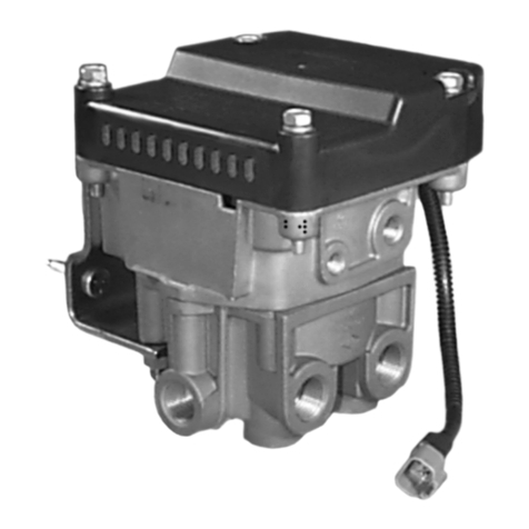
2. Install a gauge at theATR-2™valve service port and at
one of the delivery ports, then install a gauge in each.
3. Connectthe tractorserviceandemergency“glad hands”
(hose couplings) to hose couplings that have been
plugged, or alternatively, to a trailer. Build the tractor
systemair pressuretogovernorcut-outand make4to 5
full brake applications. Check the air fittings at the
ATR-2™valve forleakage. Tightenasneeded.
4. Withthetrailersupplyvalve(dashcontrolw/redoctagonal
button)andsystem parkcontrol (dashcontrol w/yellow
diamond button) activated for tractor/trailer operation,
apply and release the brakes several times and check
for prompt application and release at each wheel. If
prompt reaction is noted at some, but not all wheels,
test the antilock modulator between the ATR-2™valve
and the brake chamber for proper operation. If a
“sluggish”responseis notedat allwheels, inspectfora
kinked or obstructed air line leading to or from the
ATR-2™valve. If a complete release of the brakes is
noted at some, but not all wheels, test the antilock
modulator between the ATR-2™valve and the brake
chamberfor properoperation. If anincomplete release
isnoted atall wheels,inspect fora kinkedor obstructed
airline leadingto orfrom theATR-2™valve.
5. ChecktheATR-2™valvedifferentialpressurebyapplying
10 psi to the service port and noting the pressure
registered at the delivery port. Subtract delivery port
pressure from the 10 psi service pressure to obtain the
differential. Comparethe measureddifferential withthe
pressurespecifiedfortheATR-2™valvepartnumber(see
the I.D. washer also for the differential). NOTE: For
ATR-2™valves not incorporating a relay piston return
spring(14) the measured differential should be
approximately 4 psi. When a spring is in use, the
differential willbehigher.
6. Makeandholdafull(100psiorgreater)brakeapplication
andnote thatfull pressureis deliveredtothechambers.
7. Activatethe dashmountedtrailersupplyvalve forbobtail
tractoroperation. Thenmakeaslowbrakeapplication,
increasing the pressure at the ATR-2™valve’s service
portto 20psi whilewatching thereaction atthe delivery
port gauge. Note that delivery pressure rises to
approximately 5 to 10 psi and remains constant while
service pressure continues to rise to 20 psi. Release
theapplication.
8. Makeanother brakeapplicationandslowlyincrease the
pressureattheATR-2™valve’sservice portto between
60and 70psi whileobserving thegauge installedat the
deliveryport. Notethatwhenserviceportpressure rises
to between 20 and 30 psi, delivery pressure begins to
rise above the initial pressure noted in step 6. The rise
ofdeliverypressure shouldbe ata proportionedrateof
approximately3to1. At70psiservicepressure,delivered
pressure should be 15 to 25 psi.
9. Make a full brake application and note that both test
gauges register the same pressure. IMPORTANT: If
during testing, the service port pressure is SLOWLY
increasedfrom approximately70 psito afull (100psi or
greater)brake application,theATR-2™valve MAYbegin
to cycle between an apply and exhaust mode. This
conditionisnormalwhiletheATR-2™valveistransitioning
from the proportioning mode to the full delivery mode
andwill onlyoccur ifthe serviceapplication isSLOWLY
increased as described. Cycling will not occur or can
be stopped by increasing or decreasing service port
pressure.
10. DisconnecttheATR-2™valve’stwopinsolenoidconnector
from the wire harness. Apply the probes of a volt-ohm
metertotheconnectorleadingtothesolenoidandnote
the resistance of the solenoid is between 10 and 12
ohms.
11. Applyand removevehicle power(12 vdc)tothetwopin
connector half leading to the ATR-2™valve (solenoid)
whileobserving thebrakechamber gauges. Notethata
full brake application is made and held while power is
applied to the ATR-2™valve’s solenoid and that it is
releasedwhen powerisremoved.
12. Remove thetestgauges fromtheATR-2™valve.
LEAKAGE TESTS
1. Buildthe airsystem pressuretogovernorcut-out. With
thedashmountedtrailersupplyvalveactivatedfortractor/
traileroperation,applyasoapsolutiontoallthreeexhaust
ports(two incoverand oneinbody). The leakagenoted
shouldnot exceeda 1”bubble inless than3 secondsat
any exhaust port.
2. Makeand holda fullbrake applicationandapplyasoap
solutiontoallthreeexhaustportsand aroundthe cover
where it joins the body. The leakage noted should not
exceeda1”bubbleinlessthan3secondsatanyexhaust
port.
IftheATR-2™valvefailsto functionasdescribed,orleakage
is excessive, it should be replaced with a new or genuine
Bendix remanufactured unit or repair using maintenance
kitpiecenumber 109359,availableatany Bendixauthorized
parts outlet.
VEHICLE PREPARATION
1. Parkthe vehicleonalevelsurface andblockthewheels
and/or hold the vehicle by means other than the air
brakes.
2. Drainthe airpressure fromall vehiclereservoirs.
REMOVAL
1. Identifyand markor labelall electricalwiring harnesses
and air lines and their respective connections on the
assembly to facilitate ease of installation.
2. Disconnect the air lines and wire harnesses.
3. Removethecontrollerandvalveassembly(ATR-2™valve)
fromthe vehicle.
INSTALLATION
1. Install the assembled unit on the vehicle.
2. Reconnect all air lines and wire harnesses to the unit
using the identification made during REMOVAL step 1.
