2
No two vehicles operate under identical conditions, as a
result, maintenance intervals may vary. Experience is a
valuableguidein determiningthebestmaintenance interval
forair brakesystem components.At aminimum, theTC-6™
valveshouldbeinspectedevery6 months or1500operating
hours,whichever comes first, for proper operation. Should
the TC-6™valve not meet the elements of the operational
testsnotedinthisdocument,furtherinvestigationandservice
ofthevalve maybe required.
Every900 hours,25,000milesorevery3months,dropsome
lubricant such as BW-650M silicone lubricant (Bendix part
number 291126) (Dow Corning 55-M) through the handle
operating slot, to re-lubricate the cam roller and hinge pin.
Performoperating andleakage tests.
REMOVING AND INSTALLING
Secure vehicle with spring brakes or blocks. Drain the
reservoir which supplies the TC-6™valve. Remove the
fasteners which secure the mounting bracket to the panel.
Disconnectthe connectingair lines.Removevalve.
INSTALLING
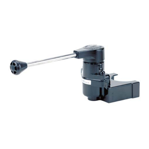
Atypicalpipingarrangement fortheTC-6™valveisshown in
Fig. 3. Check connecting air lines for integrity and foreign
material. Replace lines if necessary. Re-connect air lines.
Replace fasteners securing bracket to panel. Check
operation of valve by charging system and performing the
service check as described in this manual.
SERVICE CHECKS
OPERATING
Connect an accurate test gauge to the trailer service line
hose and leave the trailer emergency or supply hose
connectedtothe trailerorif a trailerisnot available,connect
the trailer supply hose to an unvented dummy coupling or
toa pluggedhose fitting. Thetrailer supplyvalve shouldbe
in the normal position.
When the operating lever is moved to the fully applied
position, the gauge should register full reservoir pressure.
Intermediate positions should deliver proportional
intermediate pressures. Upon release, the gauge should
immediatelyregister zero.
The location of the atmospheric end of the exhaust line
from the valve should be found, probably in the engine
compartment.
With the TC-6™valve in the release position, no pressure
shouldregister onthe test gaugeand leakageat the end of
the exhaust line should not be greater than 100 SCCM
(1" bubble in 5 seconds).
With the valve fully applied, leakage at the exhaust line
should not be greater than 175 SCCM (1" bubble in 3
seconds).
Ifthe valvedoes notfunctionas described,or ifthe leakage
is excessive, it is recommended that it be returned to the
nearest Bendix authorized distributor for a factory
remanufacturedvalveunder theexchangeplan.If thisisnot
possible,thevalvecanberepairedwithgenuineBendixparts,
in which case the following should be helpful. The
maintenancekitfor theTC-6™valveis partnumber289890.
DISASSEMBLY
Remove the valve from the panel. Place the lever in a vise
and with a firm pull the rubber handle may be removed.
Remove the two slotted head cap screws (14) which hold
themountingbracketinplaceasshownin Fig. 2andremove
themounting bracket.
Drive the pivot pin (13) out of the body with a drift punch.
Thehandle (10), roller cam(11)andtorsion spring (8) may
nowbe removed. Removethe roller camfrom the handle.
The cam follower (9), graduating spring (6), plunger (12),
andplunger returnspring (4) maynow beremoved through
thetopofthevalve. Careshouldbetakennot tolosewasher
(15).
Placethebodyina soft-jawedviseandremovecapnut (16).
Removeo-ring(1) fromcap nut.
Inletvalvespring(3)andinletvalve(2)maynowberemoved.
CLEANINGAND INSPECTION OF PARTS
Clean all metal and plastic parts with mineral spirits or
equivalent. Wipe all o-rings and rubber parts dry. Replace
any which show signs of wear or deterioration. Inspect
valve seats for nicks or burrs and remove any deposits.
Check all springs for distortion, cracks and corrosion.
Replaceallpartsnotconsideredserviceableafterinspection.
ASSEMBLY
Before assembling the valve all bores, cam, pivot pin,
plungers, and o-rings should be lubricated with silicone
lubricantDow Corning55-M (Bendix partnumber 291126).
Placebodyin asoft-jawedvise withportspointing up.Place
inletvalve (2)in inletcavity andinstall inlet valve spring (3).
Place o-ring (1) on cap nut (16) and assemble cap nut in
body. Torque cap nut to 50-150 inch pounds.
Install o-rings (5) and (7) on plunger (12) and cam follower
(9).Caution:o-ring (7)is slightlylargerthan (5)and goes on
thecam follower(9).
Reverse position of body in vise and install plunger return
spring (4), plunger (12), washer (15), graduating spring
(6), and cam follower (9). Note: The cam follower must be
positioned so that the projection on the side of the body
matches the corresponding groove in the body.
