manuals.online logo
Brands
  1. Home
  2. •
  3. Brands
  4. •
  5. BENDIX
  6. •
  7. Control Unit
  8. •
  9. BENDIX LQ-2 QUICK RELEASE VALVES User manual

BENDIX LQ-2 QUICK RELEASE VALVES User manual

1
®
SD-03-950
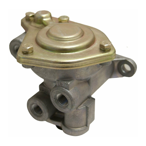
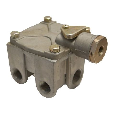
Bendix®LQ-2™Limiting & Quick Release Valve and TW-1™Control Valve
FIGURE 1
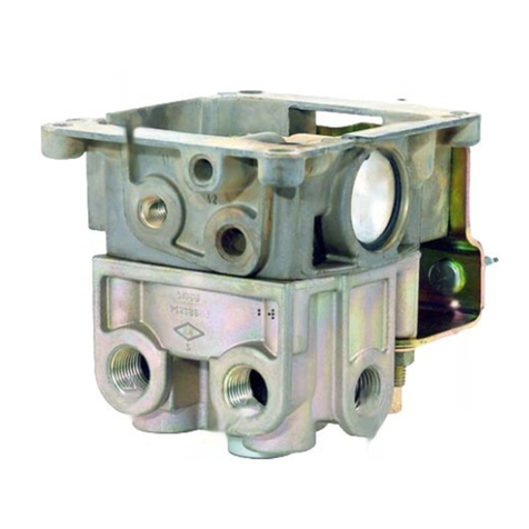
LQ-2™LIMITING & QUICK
RELEASE VALVE
FIGURE 2
DESCRIPTION
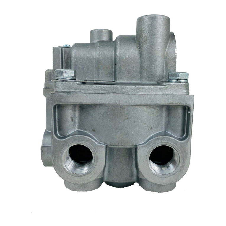
LQ-2™LIMITING & QUICK RELEASE VALVE
TheBendix®LQ-2™limitingandquickreleasevalveisadual
function valve; the valve serves to limit brake applications
andisgenerallyusedonthefrontorsteeringaxleofavehicle.
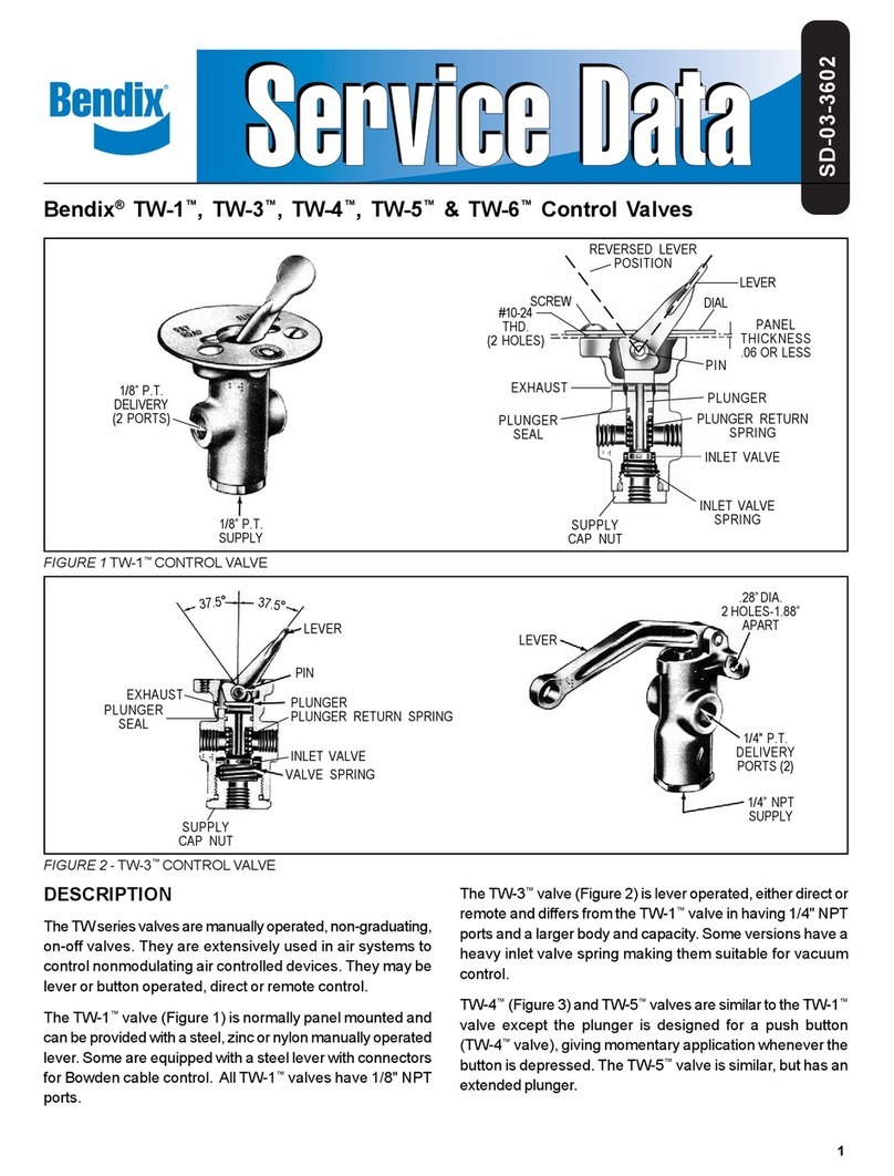
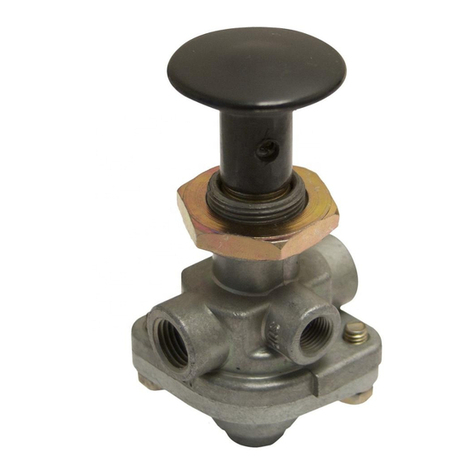
TheLQ-2™valveiscontrolledbyaTW-1™controlvalve,(see
Figure2)whichismountedinthevehiclecabwithinreachof
the driver. Placing the control valve in the “Slippery Road”
position will reduce front axle service application pressure
by 50%. With the control valve in the “Dry Road” position,
there is no reduction of service application pressure. In
addition, the LQ-2™valve serves a quick release function,
releasingair directlyfrom thefront axlechambers.
TW-1™CONTROL VALVE
PLUNGER RETURN
SPRING
INLETVALVE
SPRING
EXHAUST
PORT
LEVER
EXHAUST
VALVE
GASKET
INLET
VALVE
PISTON
INLET & EXHAUST
VALVE
STEM
O-RINGS(2)
SPRING
GUIDE
COVER SEALRING
DIAL
PLUNGER
SUPPLY PORT
(FROM BRAKE VALVE)
DELIVERY PORT
(TO BRAKE CHAMBER)
EXHAUST
PORT
CUT-OUTVALVE
PORT
(FROM
TWO-WAY
VALVE)
DELIVERY PORT (TO
LIMITING AND QUICK
RELEASE VALVE)
INLET PORT
(FROM BRAKE
VALVE)
2
OPERATION
Reference Figure 2, the LQ-2™limiting and quick release
valveandtheTW-1™controlvalveareconnectedtoaservice
applicationline:one connection istothe supply (top)portof
the limiting and quick release valve; the other is to the inlet
portof the two-waycontrol valve. Thedelivery linefrom the
two-waycontrolvalveisconnectedtothecut-out valve(side)
portof the limiting and quickrelease valve.
DRYROADPOSITION
WiththehandleoftheTW-1™controlvalveinthe“DryRoad”
position,the valve isinthe “on”positionand airispermitted
topassthrough thevalve.
Whenafootbrakevalveapplicationismade,airflowsthrough
theTW-1™controlvalveandentersthesideportofthelimiting
and quick release valve. At the same time, air also enters
the top inlet port; thus pressure acts upon the top and side
areas of the piston, moving the piston down, seating the
exhaust valve, closing the exhaust port. At the same time
the inlet valve opens and air is delivered out the delivery
ports, to the chambers.
When the air pressure beneath the piston (and in the
delivery lines) equals the air pressure being delivered by
thefoot valve,the pistonraises slightly and closes the inlet
valve. When the foot valve application is released, the air
on the top and side areas of the piston is exhausted back
throughthe footvalve;airpressurebeneaththepistonraises
it,andtheexhaustvalveopensallowingtheairinthedelivery
linesto exhaust outthe exhaust port.
SLIPPERY ROAD POSITION
Withthe handle of the TW-1™control valve in the“Slippery
Road” position, the valve is in the “off” position; the inlet
valve is seated and the exhaust is open. In this position air
isnot permitted to pass through the valve.
When a foot brake application is made, air enters only the
topinlet port. (Airdoes not enterthe side inletport because
the TW-1™control valve is “off”.) Air pressure is effective
onlyonthe upper innerarea of thepiston;the piston moves
downandtheexhaustvalveseatsandtheinletvalveopens.
Airpressureinthe delivery lineactsonthe lower areaofthe
piston,which is abouttwice the sizeof the upperinner area
ofthepiston. Thus, when the pressure acting upon thelower
areaisabout half ofthe brake valvedeliveredpressure, the
pistonlifts and closesthe inletvalve. In thisposition, theair
pressure in the brake chambers is approximately 50% of
brakevalveapplicationpressure.
WARNING! PLEASE READ AND FOLLOW
THESE INSTRUCTIONS TO AVOID
PERSONAL INJURYOR DEATH:
When working on or around a vehicle, the following
general precautions should be observed at all times.
1. Park the vehicle on a level surface, apply the
parking brakes, and always block the wheels.
Always wear safety glasses.
2. Stop the engine and remove ignition key when
working under or around the vehicle. When
working in the engine compartment, the engine
should be shut off and the ignition key should be
removed. Where circumstances require that the
enginebeinoperation,EXTREMECAUTIONshould
be used to prevent personal injury resulting from
contact with moving, rotating, leaking, heated or
electrically charged components.
3. Do not attempt to install, remove, disassemble or
assemble a component until you have read and
thoroughly understand the recommended
procedures. Useonly the proper tools and observe
all precautions pertaining to use of those tools.
4. If the work is being performed on the vehicle’s air
brake system, or any auxiliary pressurized air
systems,make certain to drain theairpressure from
all reservoirs before beginning ANY work on the
vehicle. If the vehicle is equipped with an AD-IS™
air dryer system or a dryer reservoir module, be
sure to drain the purge reservoir.
5. Following the vehicle manufacturer’s
recommendedprocedures,deactivate the electrical
system in a manner that safely removes all
electrical power from the vehicle.
6. Never exceed manufacturer’s recommended
pressures.
7. Never connect or disconnect a hose or line
containing pressure; it may whip. Never remove a
component or plug unless you are certain all
system pressure has been depleted.
8. Use only genuine Bendix®replacement parts,
components and kits. Replacement hardware,
tubing, hose, fittings, etc. must be of equivalent
size, type and strength as original equipment and
be designed specifically for such applications and
systems.
9. Components with stripped threads or damaged
parts should be replaced rather than repaired. Do
not attempt repairs requiring machining or welding
unless specifically stated and approved by the
vehicle and component manufacturer.
10. Prior to returning the vehicle to service, make
certain all components and systems are restored
to their proper operating condition.
3
PREVENTIVE MAINTENANCE
Important: Review the Bendix Warranty Policy before
performinganyintrusivemaintenanceprocedures.Awarranty
maybevoided if intrusivemaintenanceis performed during
thewarrantyperiod.
No two vehicles operate under identical conditions, as a
result, maintenance intervals may vary. Experience is a
valuableguideindeterminingthebestmaintenance interval
forairbrake system components.Ataminimum,thelimiting,
quickrelease,andTW-1™valvesshouldbeinspectedevery
12months or 3600operating hours, whichevercomes first,
forproperoperation. Should thelimiting,quick release, and
TW-1™valvesnotmeettheelementsof the operational tests
notedin thisdocument, further investigation and serviceof
thevalvemayberequired.
OPERATING AND LEAKAGE TESTS
OPERATINGTEST
For this check, two accurate test gauges will be needed.
Installone gaugein abrake chamber delivery line, and the
other in the foot valve delivery line.
1. Place the control valve in the “Dry Road” position and
makeafootvalveapplication.Readingsonbothgauges
shouldbe the same.
Release the application and note that air is exhausted
promptlyfrom theexhaust portof the limiting and quick
releasevalve.
2. Place the control valve in the “Slippery Road” position
and apply the foot valve. The pressure reading on the
gauge in the brake chamber line should be 50% of the
reading of the gauge in the foot valve delivery line.
LEAKAGETEST
1. Placethecontrol valve inthe“Dry Road” position. Make
and hold a foot valve application. Coat the exhaust of
the limiting and quick release valve with soap suds;
leakage should not exceed a 1" bubble in 3 seconds.
2. Place the control valve in the “Slippery Road” position.
Makeand hold a footvalveapplication.Coattheexhaust
oftheTW-1™controlvalve;leakageshouldnotexceeda
1" bubble in 3 seconds.
If the valve does not function as described above, or if
leakage is excessive, it is recommended that the valve be
replaced with a new or remanufactured unit, or repaired
withgenuine Bendix parts.
REMOVINGAND INSTALLING
Block and hold vehicle by means other than air brakes.
LIMITING & QUICK RELEASE VALVE
Identify all lines to facilitate installation; disconnect lines
andremovevalve.
TW-1™CONTROLVALVE
1. Identify lines to facilitate installation.
2. Disconnect lines.
3. Remove two screwsonvalve dial plate.
4. Removedialplate
5. Removevalve.
INSTALLING
LIMITINGANDQUICK RELEASE VALVE
1. Locate valve near front axle in close proximity to the
chambersit serves.
2. Install valve with exhaust port, pointing down. Use two
mountingboltsand tightensecurely.
3. Connect brake chamber lines to delivery ports.
4. Connect brake valve delivery line to top inlet port and
linefrom controlvalve to side inlet port.
TW-1™CONTROLVALVE
1. Placevalvehandlethroughmounting hole.
2. Install dial plate;tighten screws.
3. Connectair lines:
(a) frombrake valve toinletport.
(b) tolimitingandquickreleasevalvefromdeliveryport.
DISASSEMBLY
LIMITING AND QUICK RELEASE VALVE
1. Removefour(4)capscrewsand lockwashers; separate
cover, sealing ring and body.
2. Push piston from body.
3. Removepistono-rings.
4. Removeexhaustvalve,valveguideandspring.
5. Pull thevalvestemthroughthepiston;remove inlet valve
fromstem.
TW-1™CONTROLVALVE
1. Removeinletvalvecapnut,springandinlet/exhaustvalve.
Removecap nut seal ring.
2. Drive out lever pin andremove lever.
3. Remove plunger andplunger spring.
4. Removeplungero-ring.
4
BW1439 © 2004 Bendix Commercial Vehicle Systems LLC All rights reserved. 3/2004 Printed in U.S.A.
CLEANING AND INSPECTION
Wash all metal parts in mineral spirits; wipe rubber parts dry.
Inspect all parts for signs of wear and/or deterioration.
Inspectspringsforcracks,distortionorcorrosionand inspect
all metal valve seats for nicks or scratches.
It is recommended that all rubber parts be replaced, and
that any part showing signs of wear or deterioration be
replaced.
ASSEMBLY
LIMITINGANDQUICK RELEASE VALVE
1. Installinletvalveonstem(note:lubricatingthevalvewith
silicone will aid installation).
2. Insert stem through pistons, position spring and valve
guideover stem andpressexhaust valvebooton stem.
3. Lubricatebodyandcoverbores,o-ringsando-ringgrooves
withDowCorning55Mpneumatic grease (Bendix piece
no.291126).
4. Install o-rings on piston assembly.
5. Installpistonassemblyin body.Be careful nottodamage
o-rings.
6. Install sealing ring in body; install cover to body.
7. Install four (4) cap screws/lockwashers; torque to
approximately100 inch pounds.
TW-1™CONTROLVALVE
Priortoassembly, lubricate bodybores,plungerando-rings
with Dow Corning 55-M pneumatic grease (Bendix piece
no.291126).
1. Installinlet/exhaust valve andspring inbody.
2. Install cap nut and sealing ring.
3. Install plunger o-ring, plunger spring and plunger into
body.
4. Position lever in body slot, line up lever hole and install
pin.
5. Testvalves asoutlined in “Operatingand Leakage” test
section.

This manual suits for next models

1

Other BENDIX Control Unit manuals

BENDIX PRESSURE PROTECTION VALVES User manual

BENDIX

BENDIX PRESSURE PROTECTION VALVES User manual

BENDIX ATR1DC ANTILOCK TRACTION RELAY User manual

BENDIX

BENDIX ATR1DC ANTILOCK TRACTION RELAY User manual

BENDIX QR-1C DBL CHECK QUICK RELEASE VALVE User manual

BENDIX

BENDIX QR-1C DBL CHECK QUICK RELEASE VALVE User manual

BENDIX MV-1 MODUTROL Service manual

BENDIX

BENDIX MV-1 MODUTROL Service manual

BENDIX RV-1 PRESSURE REDUCING VALVE User manual

BENDIX

BENDIX RV-1 PRESSURE REDUCING VALVE User manual

BENDIX E-12-E-15 BRAKE VALVE User manual

BENDIX

BENDIX E-12-E-15 BRAKE VALVE User manual

BENDIX TC-7 TRAILER CONTROL BRAKE VALVE User manual

BENDIX

BENDIX TC-7 TRAILER CONTROL BRAKE VALVE User manual

BENDIX ATR-1 ANTILOCK TRACTION RELAY Service manual

BENDIX

BENDIX ATR-1 ANTILOCK TRACTION RELAY Service manual

BENDIX E-7 DUAL BRAKE VALVE User manual

BENDIX

BENDIX E-7 DUAL BRAKE VALVE User manual

BENDIX R-12DC DBL CHECK RELAY VALVE User manual

BENDIX

BENDIX R-12DC DBL CHECK RELAY VALVE User manual

BENDIX ATR-1 ANTILOCK TRACTION RELAY User manual

BENDIX

BENDIX ATR-1 ANTILOCK TRACTION RELAY User manual

BENDIX LQ-5 BOBTAIL RATIO VALVE User manual

BENDIX

BENDIX LQ-5 BOBTAIL RATIO VALVE User manual

BENDIX E-10PR RETARDER CTRL BRAKEVALVE User manual

BENDIX

BENDIX E-10PR RETARDER CTRL BRAKEVALVE User manual

BENDIX R-8P PRESSURE EQUALIZING PILOTRELAY User guide

BENDIX

BENDIX R-8P PRESSURE EQUALIZING PILOTRELAY User guide

BENDIX TP-3 Mounting instructions

BENDIX

BENDIX TP-3 Mounting instructions

BENDIX SR-5 TRAILER SPRING BRK VALVE User manual

BENDIX

BENDIX SR-5 TRAILER SPRING BRK VALVE User manual

BENDIX SR-5 TRAILER SPRING BRK VALVE User manual

BENDIX

BENDIX SR-5 TRAILER SPRING BRK VALVE User manual

BENDIX R-12DC Mounting instructions

BENDIX

BENDIX R-12DC Mounting instructions

BENDIX SC-3 INLINE SINGLE CHECK VALVES User manual

BENDIX

BENDIX SC-3 INLINE SINGLE CHECK VALVES User manual

BENDIX QR-L INLINE QUICK RELEASE VALVE User manual

BENDIX

BENDIX QR-L INLINE QUICK RELEASE VALVE User manual

BENDIX R-8 RELAY VALVE User manual

BENDIX

BENDIX R-8 RELAY VALVE User manual

BENDIX RE-6 RELAY EMERGENCY VALVE User manual

BENDIX

BENDIX RE-6 RELAY EMERGENCY VALVE User manual

BENDIX R-6 RELAY VALVE User manual

BENDIX

BENDIX R-6 RELAY VALVE User manual

BENDIX PR-3 User manual

BENDIX

BENDIX PR-3 User manual

Popular Control Unit manuals by other brands

EOS SBM GLT KNX Installation and operating instructions

EOS

EOS SBM GLT KNX Installation and operating instructions

TOPSKY PRIME-1 quick start guide

TOPSKY

TOPSKY PRIME-1 quick start guide

Flashcut CNC 401A Hardware guide

Flashcut CNC

Flashcut CNC 401A Hardware guide

VAT 150 Series Installation, operating,  & maintenance instructions

VAT

VAT 150 Series Installation, operating, & maintenance instructions

Giga-tronics 3000-12 manual

Giga-tronics

Giga-tronics 3000-12 manual

WAGO 751-5202 manual

WAGO

WAGO 751-5202 manual

Acromag VPX6600 user manual

Acromag

Acromag VPX6600 user manual

Infineon TLE9262-3BQX manual

Infineon

Infineon TLE9262-3BQX manual

Panasonic SF-C13 instruction manual

Panasonic

Panasonic SF-C13 instruction manual

Bristan OP TS1503 EL C Installation instructions and user guide

Bristan

Bristan OP TS1503 EL C Installation instructions and user guide

Lenze EPM-H410 operating instructions

Lenze

Lenze EPM-H410 operating instructions

Elkron MP 200 Installation and maintenance manual

Elkron

Elkron MP 200 Installation and maintenance manual

Mircom RB-MD-1113 installation instructions

Mircom

Mircom RB-MD-1113 installation instructions

Sencon BCM500 instruction manual

Sencon

Sencon BCM500 instruction manual

Honeywell AlarmNet 7845GSM Quick setup guide

Honeywell

Honeywell AlarmNet 7845GSM Quick setup guide

Siemens SIMATIC ET 200SP manual

Siemens

Siemens SIMATIC ET 200SP manual

GEM 567 servoDrive operating instructions

GEM

GEM 567 servoDrive operating instructions

OMEX 200 Series installation manual

OMEX

OMEX 200 Series installation manual

manuals.online logo
manuals.online logoBrands
  • About & Mission
  • Contact us
  • Privacy Policy
  • Terms and Conditions

Copyright 2025 Manuals.Online. All Rights Reserved.