7
2. Stop the engine and remove ignition key when
working under or around the vehicle. When
working in the engine compartment, the engine
should be shut off and the ignition key should be
removed. Where circumstances require that the
enginebeinoperation,EXTREMECAUTIONshould
be used to prevent personal injury resulting from
contact with moving, rotating, leaking, heated or
electrically charged components.
3. Do not attempt to install, remove, disassemble or
assemble a component until you have read and
thoroughly understand the recommended
procedures. Useonlythepropertoolsandobserve
all precautions pertaining to use of those tools.
4. If the work is being performed on the vehicle’s air
brake system, or any auxiliary pressurized air
systems, make certain to drain the air pressure
from all reservoirs before beginning ANY work on
the vehicle. If the vehicle is equipped with an
AD-IS™airdryersystemoradryerreservoirmodule,
be sure to drain the purge reservoir.
5. Following the vehicle manufacturer’s
recommendedprocedures,deactivatetheelectrical
systeminamannerthatsafelyremovesallelectrical
power from the vehicle.
6. Never exceed manufacturer’s recommended
pressures.
7. Never connect or disconnect a hose or line
containing pressure; it may whip. Never remove a
component or plug unless you are certain all
system pressure has been depleted.
8. Use only genuine Bendix®replacement parts,
components and kits. Replacement hardware,
tubing, hose, fittings, etc. must be of equivalent
size, type and strength as original equipment and
bedesignedspecificallyforsuchapplicationsand
systems.
9. Components with stripped threads or damaged
parts should be replaced rather than repaired. Do
notattemptrepairsrequiringmachiningorwelding
unless specifically stated and approved by the
vehicle and component manufacturer.
10. Prior to returning the vehicle to service, make
certainallcomponentsandsystemsarerestoredto
their proper operating condition.
OPERATION & LEAKAGE TESTS
Operating Test
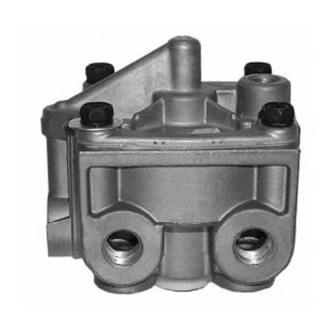
To properlytestthe functionoftheAR-2™valve,a pairoftest
gauges or gauges of known accuracy must be used.
1. Install a “tee” at the AR-2™valve’s service port and at
one of the delivery ports, then install a gauge in each.
2. Connectthetractorserviceandemergency“glad hands”
(hosecouplings) todummyconnectors,oralternatively,
to a trailer. Build the tractor system air pressure to
governorcut-outandmake4to5fullbrake applications.
Check the air fittings at the AR-2™valve for leakage.
Tightenas needed.
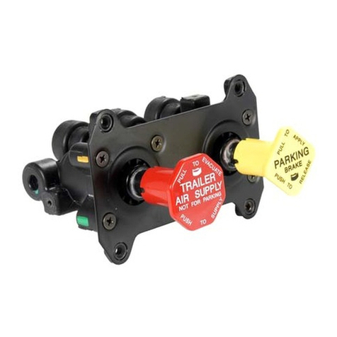
3. Withthetrailersupplyvalve(dashcontrolw/redoctagonal
button)andsystem parkcontrol (dashcontrol w/yellow
diamond button) activated for tractor/trailer operation,
apply and release the brakes several times and check
for prompt application and release at each wheel. If
prompt reaction is noted at some, but not all wheels,
test the M-21™antilock modulator between the AR-2™
valve and the brake chamber for proper operation. If a
“sluggish”response is notedat allwheels, inspectfora
kinkedorobstructedairlineleading toorfrom theAR-2™
valve. If a complete release of the brakes is noted at
some, but not all wheels, test the M-21™antilock
modulator between the AR-2™valve and the brake
chamberforproper operation.If anincomplete release
isnoted atall wheels,inspect fora kinkedor obstructed
airline leadingto orfrom theAR-2™valve.
4. ChecktheAR-2™valve’sdifferentialpressurebyapplying
10 psi to the service port and noting the pressure
registered at the delivery port. Subtract delivery port
pressure from the 10 psi service pressure to obtain the
differential.Compare themeasured differentialwith the
pressure specified for the AR-2™valve part number.
NOTE:ForAR-2™valvesnotincorporatinga relaypiston
return spring the measured differential should be
approximately 4 psi. When a spring is in use, the
differentialwill behigher.
5. Makeandholdafull(100psiorgreater)brakeapplication
and note that full pressure is delivered to the brake
chambers.
6. Activatethe dashmountedtrailersupplyvalveforbobtail
tractor operation. Then make a slow brake application,
increasingthe pressureattheAR-2™valve serviceport
to20 psiwhile watchingthe reactionat thedelivery port
gauge.Notethatdeliverypressurerisestoapproximately
5to 10psi andremainsconstant whileservice pressure
continues to rise to 20 psi. Release the application.
7. Make another brake application and slowly increase
thepressure attheAR-2™valveserviceportto between
60and 70psi whileobserving thegauge installedatthe
deliveryport. Notethatwhen serviceportpressure rises
to between 20 and 30 psi, delivery pressure begins to
rise above the initial pressure noted in step 6. The rise
ofdelivery pressure shouldbe ata proportionedrate of
approximately 3to1. Forexample:Each3psiincrease
attheservice portresultsin adeliverypressureincrease
of1 psi.At70 psiserviceportpressure, brakechamber
pressure should be 15 to 25 psi.
8. Make a full brake application and note that both test
gauges register the same pressure. IMPORTANT: If
during testing the service port pressure is SLOWLY
increased from approximately 70 psi to a full (100 psi
orgreater)brakeapplication,theAR-2™valveMAYbegin
to cycle between an apply and exhaust mode. This
