manuals.online logo
Brands
  1. Home
  2. •
  3. Brands
  4. •
  5. BENDIX
  6. •
  7. Control Unit
  8. •
  9. BENDIX E-2-E-3 BRAKE VALVES User manual

BENDIX E-2-E-3 BRAKE VALVES User manual

®
SD-03-812
DESCRIPTION
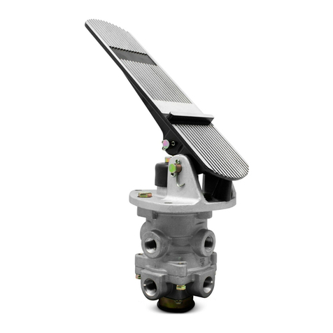
The Bendix®E-2™and E-3™brake valves are single circuit
brakevalvesthatprovidethedriverwithsinglepointcontrol
oftheservicebrakingsystem.Thevalvecanbeeithertreadle
operated or fitted with a lever for a linkage connection to a
conventionalbrakepedal. Movement of thetreadleorpedal
controlsthegraduatedapplicationandreleaseofairpressure
to the vehicle brake actuators, applying or releasing the
vehiclebrakes.
The E-2™and E-3™brake valves utilize a rubber spring
confinedinaretainer,resultinginreducedplungertravelas
comparedtopreviousdesignsinglecircuitbrakevalves.
The E-3™brake valve differs from the E-2™valve in that it
employsadifferent piston (see insertFig.1),whichrequires
greaterplungertravel.Becauseofthegreaterplungertravel,
the E-3™valve provides less sensitivity in the 0-40 psi
applicationrange ascomparedto theE-2™valve.Otherthan
thedifferentpistons, the E-2™and E-3™valves areidentical.
Anidentificationwasher, located under the retainingringin
thevalve’sexhaust port, providesameansofidentifying the
E-2™andE-3™brakevalve.
TheE-2™andE-3™valveshaveaninserttypeinlet/exhaust
valveassemblywhichcanberemovedwithoutdisconnecting
airlines.Anexhaust checkvalve in the bottom ofthe insert
preventscontaminantsfrom entering the valve through the
exhaust port. An optional exhaust extension is available
shouldanexhaustcarry-offline be required.
Portingconsistsoftwo(2)1/2inchp.t.supplyports,four(4)
3/8 inch or 1/2 inch p.t. delivery ports, and two (2) 1/4 inch
p.t. accessory ports (in the supply portion of the valve).
OPERATION
Applying
Applyingthe treadle or pedal exertsaforceon the plunger,
rubber graduating spring and piston. The downward
movement of the piston causes the piston stem (which is
theexhaustseat) to contact the valve,closingthe exhaust.
As the exhaust closes, the inlet valve moves away from its
seat. Air pressure is then allowed to flow by the inlet valve,
out the delivery ports and to the brake actuators, applying
thebrakes.
Balanced
When the air pressure in the cavity beneath the piston and
theairpressurebeingdeliveredtothebrakeactuatorsequals
the mechanical force on the top of the piston, the piston
liftsandthe inlet valve closes,cuttingoff any further flow of
air from the supply line through the valve. The exhaust
remains closed, preventing any escape of air through the
exhaustport.
Bendix®E-2™& E-3™Brake Valves
FIGURE1 E-3™BRAKEVALVE(SECTIONALVIEW)
RETAINER
O-RING
PISTON
RETURN
SPRING
RETAINING
RING
PRELOAD
SPRING
EXHAUSTCH.
VALVESEAT
INLET/EXHAUST
VALVE
CAPSCREW
INSERTASS’Y
SPRINGSEAT
WASHER
RUBBERSPRING
RETAINER
VALVESPRING
O-RING
O-RING
DIAPHRAGM
WASHER
SCREW 11
10
6
2
3
1
4
12
89
21 20
19 18
17
16
15
14
13
MOUNTING
PLATE
TREADLE
AUXILIARY
PORTS (2)
DELIVERY
PORTS (4)
EXHAUST
SUPPLY
PORTS (2)
7
PISTON
E-2™-E-3™BRAKE VALVE
Whenapplications intheaboveaveragepressure rangeare
made, the valve reaches a balanced position as the air
pressurebeneaththe piston equalstheeffortexertedbythe
driver’s foot on the pedal or treadle. When the piston is
presseddownallthe way,theinlet valve remains open and
reservoirpressureisdeliveredtotheactuators.
Releasing
Whenthetreadleorpedalapplicationisreleased,mechanical
force is removed from the top of the piston, air pressure
beneaththepistonlifts the piston; (the inlet valve isclosed)
the exhaust in the valve is open and the air beneath the
piston and in the delivery lines is exhausted through the
exhaustport.
PREVENTIVE MAINTENANCE
Important: Review the warranty policy before performing
anyintrusivemaintenanceprocedures.Anextendedwarranty
maybevoidedifintrusivemaintenanceisperformedduring
thisperiod.
Becauseno twovehiclesoperateunder identicalconditions,
maintenanceandmaintenanceintervalswillvary.Experience
is a valuable guide in determining the best maintenance
intervalforanyoneparticularoperation.
Visuallycheckforphysicaldamagetothebrake valve such
as broken air lines and broken or missing parts.
Every3Months, 25,000 Miles or 900OperatingHours
Lubricate all mechanical actuation (pedal) parts with light
(10W)oil.Apply 2 to 4dropsof oil between theplungerand
mountingplate.DONOT OVER OIL!!!
Lever/linkage operated valves should be adjusted so that
therollerjustcontactsplunger.Checkforintegrityofmounting
plateandtreadleand/orpedal.
SERVICE TESTS
Operating Test (IMPORTANT!!! Tests should be
conducted with an accurate test gauge.)
Installgaugein a delivery port orline;depressthetreadleor
pedal to several positions between fully released and fully
applied positions, checking the delivery pressure on the
gaugetoseethatitvariesproportionatelywiththemovement
of the treadle or pedal. In the fully applied position, the
reading on the gauge should be approximately that of full
reservoir pressure. Upon release of the application, the
readingofthe test gauge shouldfalltozeropsiimmediately.
Leakage Test
With100 psi supplypressureandvalvein releasedposition,
coat exhaust port with soapsuds arid check for leakage.
NOleakagepermitted.
Fully apply valve and hold application. Coat exhaust port
with soapsuds. NO leakage permitted. Coat area around
topofvalvewithsoapsuds. NO leakage permitted.
If the valve does not function as described or leakage is
excessive,itisrecommendedthatitbe replaced with a new
orremanufacturedunit,orrepairedwithgenuineBendixparts
availableatourdistributors.
REMOVING AND INSTALLING
Removing
Block and hold vehicle by means other than air brakes.
Drain air brake system.
*If only the insert is to be removed, remove retaining ring,
and pull insert out.
If entire valve is to be removed, disconnect air lines from
valve.
Removemounting bolts andremovevalve.
Installing
Clean air lines connecting to valve.
Installvalveandtighten mounting bolts.
Connect air lines to valve (plug any unused ports).
Testvalve as outlined under “Service Tests.”
NOTE: When installing a new or rebuilt insert, precheck
movement of the inlet and exhaust valve in the
exhaust seat by depressing the insert. Precaution
shouldbetakentopreventdamagetotheinletand
exhaustvalveandtheexhaustcheckvalvegrommet,
wheninstallingtheinsertin the valve.Afterplacing
the insert in the valve body, depress the exhaust
checkvalve seatandinstallthe retainingring.Make
suretheretaining ring snaps intothebody groove.
DISASSEMBLY
NOTE: Disassemblyandassemblyinstructions are keyed
to Fig. 1 sectional view.
1. Removetreadleorleverassembly, boot and plunger.
2. Depresspistonassemblyandremoveretainer (4).
3. Removepistonassembly (7)andpistonreturn spring(2)
frombody.
4. Removeo-ring(3) from piston (7).
5. Remove cap screw (6), washer (8), spring seat (9),
and rubber spring (10) from piston assembly (7).
6. Remove retaining ring (1) and inlet/exhaust insert
assembly(11)frombody.
2
InsertDisassembly
NOTE: It is recommended that entire inlet/exhaust insert
be replaced as an assembly.
7. Removeo-ring(17) from check valveseat(16).
8. Removescrew(20), washer (19), and diaphragm(18).
9. Depressandholdinsert,andremovepreloadspring(21).
10. Remove inlet/exhaustvalve (14),valve spring(13), and
o-ring(15).
11. Removevalveretainer(12).
Cleaning and Inspection
Wash all metal parts in mineral spirits and dry. Wipe all
rubberpartsclean.
Inspectallparts for excessive wear or deterioration.
Inspectvalveandvalveseatsfornicksandburrs.
Check springs for cracks, distortion or corrosion.
Inspect exhaust check diaphragm for flexibility, wear, and
deterioration.
Replace all parts not considered serviceable during these
inspections.
ASSEMBLY
1. Lightlylubricatethepiston, valve bores,ando-ringswith
DowCorning55-Mpneumaticgrease(Ourpiecenumber
291126).
2. Positionrubber spring (10) in piston(7).
3. Install spring seat (9), washer (8), and cap screw (6).
Torque cap screw to 50 inch pounds.
4. Installpistono-ring (3) and place pistonreturnspring(2)
in body.
5. Install piston retainer (4). Be certain the prongs snap
overgrooveinvalvebody.
InsertAssembly
6. Positionpreloadspring (21) in exhaust checkvalveseat
(16).
7. Installdiaphragm(18), diaphragm washer (19)(withlips
pointing out), and install screw (20). Tighten screw
securely.
8. Installo-ring(15)andvalveretainer(12)oninlet/exhaust
valvebody(14).
9. Installvalvespring (13)onexhaust checkvalveseat(16)
andinstallinlet/exhaustvalve(14)intoexhaustvalveseat
(16).Press thevalvedown untilthepreload springsnaps
andholds the assembly together.
10. Install o-ring(17)onexhaust checkvalve seat(16).
11. Place inlet/exhaust insert in valve body; position
identification washer. Press the insert down while
installing retaining ring (1). Make certain retaining ring
snaps into body groove, thus locking in the insert in
place.
Testing A Rebuilt E-2™or E-3™Brake Valve
Performoperatingandleakagetests as outlined in “Service
Tests” section.
WARNING! PLEASE READ AND FOLLOW
THESE INSTRUCTIONS TO AVOID
PERSONAL INJURYOR DEATH:
When working on or around a vehicle, the following
general precautions should be observed at all times.
1. Park the vehicle on a level surface, apply the
parking brakes, and always block the wheels.
Always wear safety glasses.
2. Stop the engine and remove ignition key when
working under or around the vehicle. When
working in the engine compartment, the engine
should be shut off and the ignition key should be
removed. Where circumstances require that the
enginebe in operation, EXTREMECAUTIONshould
be used to prevent personal injury resulting from
contact with moving, rotating, leaking, heated or
electrically charged components.
3. Do not attempt to install, remove, disassemble or
assemble a component until you have read and
thoroughly understand the recommended
procedures. Useonlythe proper tools and observe
all precautions pertaining to use of those tools.
4. If the work is being performed on the vehicle’s air
brake system, or any auxiliary pressurized air
systems,make certaintodrain theair pressure from
all reservoirs before beginning ANY work on the
vehicle. If the vehicle is equipped with an AD-IS™
air dryer system or a dryer reservoir module, be
sure to drain the purge reservoir.
5. Following the vehicle manufacturer’s
recommendedprocedures, deactivate the electrical
system in a manner that safely removes all
electrical power from the vehicle.
6. Never exceed manufacturer’s recommended
pressures.
7. Never connect or disconnect a hose or line
containing pressure; it may whip. Never remove a
component or plug unless you are certain all
system pressure has been depleted.
8. Use only genuine Bendix®replacement parts,
components and kits. Replacement hardware,
tubing, hose, fittings, etc. must be of equivalent
size, type and strength as original equipment and
be designed specifically for such applications and
systems.
9. Components with stripped threads or damaged
parts should be replaced rather than repaired. Do
not attempt repairs requiring machining or welding
unless specifically stated and approved by the
vehicle and component manufacturer.
10. Prior to returning the vehicle to service, make cer-
tain all components and systems are restored to
their proper operating condition.
3
BW1564 © 2004 Bendix Commercial Vehicle Systems LLC. All rights reserved. 3/2004 Printed in U.S.A.

This manual suits for next models

2

Other BENDIX Control Unit manuals

BENDIX E-10PR RETARDER CTRL BRAKEVALVE User manual

BENDIX

BENDIX E-10PR RETARDER CTRL BRAKEVALVE User manual

BENDIX AR-1 ANTILOCK RELAY VALVE User manual

BENDIX

BENDIX AR-1 ANTILOCK RELAY VALVE User manual

BENDIX RV-1 PRESSURE REDUCING VALVE User manual

BENDIX

BENDIX RV-1 PRESSURE REDUCING VALVE User manual

BENDIX EVERFLOW User manual

BENDIX

BENDIX EVERFLOW User manual

BENDIX PP-1-2-5-8-RD-3 PUSH-PULL VALVES User manual

BENDIX

BENDIX PP-1-2-5-8-RD-3 PUSH-PULL VALVES User manual

BENDIX E-7 DUAL BRAKE VALVE User manual

BENDIX

BENDIX E-7 DUAL BRAKE VALVE User manual

BENDIX TP-3 TRACTOR PROTECTION VALVE User manual

BENDIX

BENDIX TP-3 TRACTOR PROTECTION VALVE User manual

BENDIX TW-N TWO WAY CONTROL VALVE User manual

BENDIX

BENDIX TW-N TWO WAY CONTROL VALVE User manual

BENDIX DUAL RELAY VALVE User manual

BENDIX

BENDIX DUAL RELAY VALVE User manual

BENDIX R-12P PILOT RELAY VALVE User manual

BENDIX

BENDIX R-12P PILOT RELAY VALVE User manual

BENDIX MV-2 CONTROL MODULE User manual

BENDIX

BENDIX MV-2 CONTROL MODULE User manual

BENDIX R-8 RELAY VALVE User manual

BENDIX

BENDIX R-8 RELAY VALVE User manual

BENDIX QR-L INLINE QUICK RELEASE VALVE User manual

BENDIX

BENDIX QR-L INLINE QUICK RELEASE VALVE User manual

BENDIX SR-1 SPRING BRAKE VALVE User manual

BENDIX

BENDIX SR-1 SPRING BRAKE VALVE User manual

BENDIX E-10 Mounting instructions

BENDIX

BENDIX E-10 Mounting instructions

BENDIX ATR1DC ANTILOCK TRACTION RELAY User manual

BENDIX

BENDIX ATR1DC ANTILOCK TRACTION RELAY User manual

BENDIX TP-3DC TRACTOR PROTECTION VALVE User manual

BENDIX

BENDIX TP-3DC TRACTOR PROTECTION VALVE User manual

BENDIX ATR1DC ANTILOCK TRACTION RELAY User manual

BENDIX

BENDIX ATR1DC ANTILOCK TRACTION RELAY User manual

BENDIX TC-6 BRAKE VALVE User manual

BENDIX

BENDIX TC-6 BRAKE VALVE User manual

BENDIX TIM G2 User manual

BENDIX

BENDIX TIM G2 User manual

BENDIX E-10 DUAL BRAKE VALVES User manual

BENDIX

BENDIX E-10 DUAL BRAKE VALVES User manual

BENDIX TP-2 TRACTOR PROTECTION VALVE User manual

BENDIX

BENDIX TP-2 TRACTOR PROTECTION VALVE User manual

BENDIX R-8R ELAY VALVE User manual

BENDIX

BENDIX R-8R ELAY VALVE User manual

BENDIX TP-3 Mounting instructions

BENDIX

BENDIX TP-3 Mounting instructions

Popular Control Unit manuals by other brands

Allmatic BIOS2 ECO Manual for installation

Allmatic

Allmatic BIOS2 ECO Manual for installation

VitaLight 576841 user manual

VitaLight

VitaLight 576841 user manual

Samson 3711 Mounting and operating instructions

Samson

Samson 3711 Mounting and operating instructions

Flowserve MASTER STATION IV EEP-SN4001 User instructions

Flowserve

Flowserve MASTER STATION IV EEP-SN4001 User instructions

Belimo SHP Series Installation Recommendations

Belimo

Belimo SHP Series Installation Recommendations

Copley Controls Accelnet Plus AEV-090-14 user guide

Copley Controls

Copley Controls Accelnet Plus AEV-090-14 user guide

Sanhua SBV Series instructions

Sanhua

Sanhua SBV Series instructions

Daikin EKWUFHTA1V3 installation manual

Daikin

Daikin EKWUFHTA1V3 installation manual

TruSens HC-SR505 manual

TruSens

TruSens HC-SR505 manual

Ampetronic ATT-U Handbook

Ampetronic

Ampetronic ATT-U Handbook

Dart DP10 instruction manual

Dart

Dart DP10 instruction manual

Rehau NEA SMART 2.0 Quick install

Rehau

Rehau NEA SMART 2.0 Quick install

ITRON 60W Endpoint installation guide

ITRON

ITRON 60W Endpoint installation guide

Edwards GSA-CC1 Installation sheet

Edwards

Edwards GSA-CC1 Installation sheet

Sensitron MULTISCAN++S1 Installation and use manual

Sensitron

Sensitron MULTISCAN++S1 Installation and use manual

York OPTIVIEW Operation manual

York

York OPTIVIEW Operation manual

MFB OSC-02 operating manual

MFB

MFB OSC-02 operating manual

Elk Products ELK-110 quick start guide

Elk Products

Elk Products ELK-110 quick start guide

manuals.online logo
manuals.online logoBrands
  • About & Mission
  • Contact us
  • Privacy Policy
  • Terms and Conditions

Copyright 2025 Manuals.Online. All Rights Reserved.