BENDIXKing KLN 94 User manual

INSTALLATION MANUAL
KLN 94
MANUAL NUMBER 006-10599-0004
REVISION 4 JANUARY, 2003
B
GPS NAVIGATION SYSTEM

WARNING
Prior to export of this document, review for export license requirement is needed.
COPYRIGHT NOTICE
2000, 2003 Honeywell International, Inc.
Reproduction of this publication or any portion thereof by any means without the expressed
written permission of Honeywell is prohibited. For further information contact the Manager
of Technical Publications, Honeywell, Olathe, KS 66061. Telephone: (913) 782-0400

BKLN 94
Rev. 4, Jan/2003 10599I04.CDL RH-1
REVISION INSTRUCTIONS AND HISTORY
MANUAL KLN 94 GPS NAVIGATION SYSTEM INSTALLATION
REVISION 2
PART NUMBER 006-10599-0002
Where R & R appears in the action column, remove the page now in the installation man-
ual and replace it with the enclosed page; otherwise, ADD or DESTROY pages as listed.
Retain these instructions in the front of the installation manual as a Record of Revisions.
______________________________________________________________________
PAGE ACTION REASON FOR CHANGE
______________________________________________________________________
KLN 94 IM Covers R&R Updated
Revision History ADD Updated
1-1 thru 1-6 R&R Updated
1-9 thru 1-10 R&R Corrected
2-5 thru 2-12 R&R Updated
2-23 thru 2-82 R&R Updated

BKLN 94
Rev. 4, Jan/2003 10599I04.CDL RH-2
REVISION INSTRUCTIONS AND HISTORY
MANUAL KLN 94 GPS NAVIGATION SYSTEM INSTALLATION
REVISION 3
PART NUMBER 006-10599-0003
Where R & R appears in the action column, remove the page now in the installation man-
ual and replace it with the enclosed page; otherwise, ADD or DESTROY pages as listed.
Retain these instructions in the front of the installation manual as a Record of Revisions.
______________________________________________________________________
PAGE ACTION REASON FOR CHANGE
______________________________________________________________________
KLN 94 IM Covers R&R Updated
Revision History R&R Updated
1-5 thru 1-6 R&R Corrected

BKLN 94
Rev. 4, Jan/2003 10599I04.CDL RH-3
REVISION INSTRUCTIONS AND HISTORY
MANUAL KLN 94 GPS NAVIGATION SYSTEM INSTALLATION
REVISION 4
PART NUMBER 006-10599-0004
Where R & R appears in the action column, remove the page now in the installation man-
ual and replace it with the enclosed page; otherwise, ADD or DESTROY pages as listed.
Retain these instructions in the front of the installation manual as a Record of Revisions.
______________________________________________________________________
PAGE ACTION REASON FOR CHANGE
______________________________________________________________________
KLN 94 IM Covers R&R Updated
Revision History R&R Updated
1-5 thru 1-6 R&R Revised
2-78 thru 2-79 R&R Revised

BKLN 94
Rev. 4, Jan/2003 10599I04.CDL RH-4
THIS PAGE IS RESERVED

BKLN 94
Rev. 4, Jan/2003 10599I04.CDL Toc i
SECTION I
GENERAL INFORMATION
Paragraph Page
1.1 INTRODUCTION ............................................................................................... 1-1
1.2 EQUIPMENT DESCRIPTION ........................................................................... 1-1
1.3 TECHNICAL CHARACTERISTICS ................................................................... 1-1
1.3.1 KLN 94 Technical Characteristics ..................................................................... 1-1
1.3.2 KA 91 Antenna Technical Characteristics .......................................................... 1-5
1.3.3 KA 92 Antenna Technical Characteristics .......................................................... 1-5
1.3.4 KA 198 Comm Filter Technical Characteristics ................................................. 1-5
1.4 UNITS AND ACCESSORIES SUPPLIED ......................................................... 1-6
1.4.1 KLN 94 GPS Receiver ....................................................................................... 1-6
1.4.2 GPS Antenna .................................................................................................... 1-6
1.4.3 KLN 94 Installation Kit ....................................................................................... 1-6
1.4.4 KA 91/92 Installation Kit .................................................................................... 1-7
1.4.5 Database ........................................................................................................... 1-8
1.5 ACCESSORIES REQUIRED, BUT NOT SUPPLIED ........................................ 1-8
1.5.1 Forced Air Cooling ............................................................................................. 1-8
1.5.2 Indicators and HSIs ........................................................................................... 1-9
1.5.3 CDI Indicator With “MSG” and “WPT” Annunciators ......................................... 1-9
1.6 OPTIONAL ACCESSORIES ............................................................................. 1-9
1.6.1 PC Interface Kit ................................................................................................. 1-9
1.6.2 Annunciators and Switch / Annunciators ........................................................... 1-10
1.6.3 NAV / GPS Switching ........................................................................................ 1-13
1.6.4 Right Angle Connector ...................................................................................... 1-13
1.7 LICENSE REQUIREMENTS............................................................................. 1-13
1.8 RECOMMENDATIONS FOR IFR APPROVAL.................................................. 1-13
1.8.1 Aircraft Logbook Entry....................................................................................... 1-13
1.8.2 Aircraft Installation Requirements ..................................................................... 1-13
1.8.3 Approved Airplane Flight Manual Supplement.................................................. 1-14
1.8.4 Pilot’sGuide ...................................................................................................... 1-14
1.9 INSTRUCTIONS FOR CONTINUED AIRWORTHINESS ................................. 1-14

BKLN 94
Rev. 4, Jan/2003 10599I04.CDL Toc ii
SECTION II
INSTALLATION
Paragraph Page
2.1 GENERAL INFORMATION ............................................................................... 2-1
2.2 UNPACKING AND INSPECTING EQUIPMENT ............................................... 2-1
2.3 EQUIPMENT INSTALLATION ........................................................................... 2-1
2.3.1 Avionics Cooling Requirements For Panel Mounted Equip............................... 2-1
2.3.2 KLN 94 Mechanical Installation ......................................................................... 2-2
2.3.3 Antenna Selection ............................................................................................. 2-2
2.3.4 Antenna Installation Considerations .................................................................. 2-2
2.3.5 Antenna Mechanical Installation ....................................................................... 2-3
2.3.6 Electrical Installation ......................................................................................... 2-4
2.4 POST INSTALLATION CHECK OUT INFORMATION ....................................... 2-67
2.4.1 Maintenance Pages........................................................................................... 2-67
2.4.2 Post Installation Checkout Procedure ............................................................... 2-73
2.4.3 Installation Check Out ....................................................................................... 2-74
2.4.4 Integrated Installation Check Out ...................................................................... 2-75
2.5 ERROR CODES ................................................................................................ 2-80
SECTION III
OPERATION
Paragraph Page
3.1 GENERAL INFORMATION ............................................................................... 3-1
APPENDIXES
APPENDIX A - RS 232 FORMAT DEFINITION .................................................................. A-1
APPENDIX B - SUPPLEMENTALS ..................................................................................... B-1
APPENDIX C - SUPPLEMENTAL TYPE CERTIFICATE ..................................................... C-1
APPENDIX D - DIRECT REPLACEMENT OF A KLN-89B WITH A KLN-94....................... D-1
APPENDIX E - ENVIRONMENTAL QUALIFICATION FORMS............................................ E-1

BKLN 94
Rev. 4, Jan/2003 10599I04.CDL Toc iii
LIST OF ILLUSTRATIONS
Figure Page
2-1 KLN 94 P941 CONNECTOR PIN FUNCTIONS ................................................ 2-10
2-2 KLN 94 P942 CONNECTOR PIN FUNCTIONS ................................................ 2-11
2-3 KLN 94 P943 CONNECTOR PIN FUNCTIONS ................................................ 2-13
2-4 KLN 94 CRIMPING AND INSERTION/EXTRACTION TOOLS ......................... 2-14
2-5 KLN 94 INSTALLATION DRAWING .................................................................. 2-15
2-6 KA 91 OUTLINE DRAWING .............................................................................. 2-17
2-7 KA 91 INSTALLATION DRAWING ..................................................................... 2-19
2-8 KA 91 BACKPLATE OUTLINE DRAWING ........................................................ 2-21
2-9 KA 92 OUTLINE DRAWING .............................................................................. 2-23
2-10 KA 92 INSTALLATION DRAWING ..................................................................... 2-27
2-11 KA 92 BACKPLATE OUTLINE DRAWING ........................................................ 2-29
2-12 KA 91/92 TNC ANTENNA COAX/CONNECTOR ASSEMBLY (0-40FT) ........... 2-31
2-13 KA 91/92 BMA ANTENNA COAX/CONNECTOR ASSEMBLY ......................... 2-33
2-14 KA 91/92 TNC/BMA ANTENNA COAX/CONNECTOR ASSEMBLY (0-80FT) .. 2-35
2-15KA 33 P/N 071-4037-00/01 FINAL ASSEMBLY................................................ 2-37
2-16KA 33 P/N 071-4037-00/01 OUTLINE AND MOUNTING DRAWING ............... 2-39
2-17 CUTLER-HAMMER SWITCH/ANNUN. MOUNTING DRAWING ...................... 2-41
2-18 CUTLER-HAMMER SWITCH/ANNUN. INTERNAL SCHEMATIC.................... 2-43
2-19 KLN 94 SERIAL RECEIVERS & TRANSMITTERS INTERCONNECT DWG. .. 2-47
2-20 KLN 94 ALTITUDE AND RMI / OBI INTERCONNECT DRAWING.................... 2-49
2-21 KLN 94 DEVIATION AND FLAGS INTERCONNECT DRAWING ..................... 2-51
2-22 KLN 94 OBS RESOLVER INTERCONNECT DRAWING .................................. 2-53
2-23 KLN 94 INTERCONNECT DRAWING .............................................................. 2-55
2-24 KLN 94 FCS & EXTERNAL ANNUNCIATOR INTERCONNECT DRAWING .... 2-57
2-25 KLN 94 BACKLIGHTING & ALT. ALERTINGINTERCONNECT DRAWING ..... 2-59
2-26 KLN 94 PC LOADER AND ANTENNA INTERCONNECT DRAWING .............. 2-61
2-27 KLN 94 DATALOADER/PC INTERFACE........................................................... 2-63
2-28 KLN 94 QUICKTUNE INTERCONNECT DRAWING ........................................ 2-65
LIST OF TABLES
Table Page
2-1 GPS RECEIVER ERROR CODES.....................................................................2-81
2-2 GPS PAGE MESSAGES ....................................................................................2-83
2-3 GPS SYSTEM ERROR CODES ........................................................................2-84

BKLN 94
Rev. 4, Jan/2003 10599I04.CDL Toc iv
THIS PAGE IS RESERVED.

BKLN 94
Rev. 4, Jan/2003 10599I04.CDL Page 1-1
SECTION I
GENERAL INFORMATION
1.1 INTRODUCTION
This manual contains information relative to the physical, mechanical, and electrical
characteristics of the BENDIX/KING KLN 94 Global Positioning System (GPS) Receiver. General
installation procedures are also included.
1.2 EQUIPMENT DESCRIPTION
The KLN 94 is a panel mounted, long range, GPS based airborne navigation system with a
database. The KLN 94 also provides VFR, IFR enroute, and IFR non-precision approach
functions. The primary purpose of the equipment is to provide the pilot with present position
information and to display guidance information with respect to a flight plan defined by the pilot.
Flight plan information is entered by the pilot via various knobs and buttons on the front panel.
The unit can use its present position information to determine crosstrack error, distance to
waypoint, ground speed, track angle, time to waypoint, bearing to waypoint, and advisory VNAV
guidance. The database of the KLN 94 contains information concerning airports, VORs, NDBs,
intersections, DP/STARs, outer markers, roads, rivers, railroads, lakes, etc., throughout the
database’s coverage area. Waypoints are stored in the database by their ICAO identifiers. The
ICAO identifiers are in most cases taken directly from Jeppesen Sanderson or government
aeronautical charts. The KLN 94 has instrument approach capabilities.
The information stored in the database eventually becomes out of date; therefore, to provide a
means of updating the information, the database is housed in a data card which plugs into the
front of the KLN 94. It is designed so that the user may easily remove the old database and install
a current database. A secondary method of updating the database is by loading the information
via an IBM compatible laptop computer. For more information on availability and cost of updating
the database of the KLN 94, refer to the KLN 94 Pilot’s Guide P/N 006-18207-0000.
1.3 TECHNICAL CHARACTERISTICS
1.3.1 KLN 94 TECHNICAL CHARACTERISTICS
TSO/JTSO Compliance: TSO-C129a, JTSO-C129a - See Appendix C
for environmental qualification.
Physical Dimensions: Refer to KLN 94 installation drawing, Figure
2-5
Mounting: Panel mounted with Honeywell supplied
mounting rack
Cooling Requirements: 4 CFM (cubic feet per minute) provided by
blower motor such as KA33 or equivalent.
Temperature Range: -20°C to +55°C
Altitude Range: Up to 55,000 Feet

BKLN 94
Rev. 4, Jan/2003 10599I04.CDL Page 1-2
Power Inputs: 11 to 33 VDC at 3.0 A Max. (-20°C to +55°C)
13.75 VDC @ 2.5 A Nominal
27.5 VDC @ 1.25 A Nominal
Panel Lighting Current Requirements:
14 VDC Lighting:
28 VDC Lighting:
220 mA Maximum
110 mA Maximum
SIGNAL INPUTS
GPS DISPLAYED:
OPEN:
GND
GPS displayed (when an indicator resolver is
connected to the OBS resolver inputs)
GPS not displayed (when an indicator resolver
is not connected)
TAKE HOME:
OPEN:
GND:
Normal Operation
Take Home Mode
SPARE IN 0:
These are reserved pins
for future use.
SPARE IN 1:
SPARE IN 2:
SPARE IN 3:
TEST:
OPEN:
GND:
Normal Operation
Test Mode
APPROACH ARM IN: This pin is normally open with a momentary low
while the panel button is pressed.
DATA LOADER RS 232 IN: This RS 232 input is designated to
communicate with devices, ie. air data and fuel
flow sensors via RS 232 format. (refer to RS
232 Format Definitions Appendix)
SPARE RS 232 IN: This RS 232 input is reserved for future use.
GRAY CODE INPUTS:
(A1, A2, A4, B1, B2, B4, C1, C2, C4, D4)
Gray Code Altitude Signals. (0 to 28 VDC)
These inputs are diode isolated inside the KLN
94.
OBS SIN: OBS resolver sine. Nominal input impedance is
33.8 K ohms (AC) and 100 K ohms (DC)

BKLN 94
Rev. 4, Jan/2003 10599I04.CDL Page 1-3
OBS COS: OBS resolver cosine. Nominal input impedance
is 33.8 K ohms (AC) and 100 K ohms (DC).
A/C POWER MONITOR: This pin senses the aircraft power bus voltage.
This high impedance input operates from 0 to
33 V with accuracy of 0.1 V.
CONFIGURATION MODULE: Refer to Section 2.3.6.2
SIGNAL OUTPUTS:
OBI SYNC, OBI CLOCK, & OBI DATA: Honeywell Serial Data containing bearing to
the active waypoint.
DATA LOADER/QUICKTUNETM RS 232 OUT: The Data Loader/QuickTune RS 232 output is
designed to communicate with an IBM
compatible personal computer.
GENERAL RS 232 OUT: The RS 232 output is designed to interface with
certain ARNAV ELTs and certain moving map
displays, and Shadin fuel flow systems (refer to
RS 232 Format Definitions Appendix).
GPS SENSOR RS 232 OUT: The GPS Sensor RS 232 output is a buffered
connection to the GPS sensor (Xpress)
transmitter connection to the host processor. It
is designed to interface with a EGPWS, and for
testing.
WAYPOINT ANNUNCIATE: OPEN = Inactive
LOW = Active (Output can sink up to 250 mA)
MESSAGE ANNUNCIATE: OPEN = Inactive
LOW = Active (Output can sink up to 250 mA)
APPROACH ACTIVE ANNUNCIATE: OPEN = Inactive
LOW = Active (Output can sink up to 250 mA)
APPROACH ARM ANNUNCIATE: OPEN = Inactive
LOW = Active (Output can sink up to 250 mA)
SPARE ANNUNCIATE 1: Spare annunciators are reserved for future
use.
SPARE ANNUNCIATE 2: Spare annunciators are reserved for future
use.
ROLL STEERING VALID
N/A on -0101
Valid = ≥18 V in 28 VDC installations; ≥10 V in
14 VDC installations. Invalid = ≤ 3.5 V in all
installations while sinking 1 mA. Output can
source at least 250 mA.
ROLL STEERING HI
N/A on -0101
Output Range: 550mV per degree of Bank.
2V per degree per second of
Turn Rate.

BKLN 94
Rev. 4, Jan/2003 10599I04.CDL Page 1-4
ROLL STEERING LO This is an output. It is always grounded
FCS LOC ENG: OPEN = Inactive
LOW = Active (Output can sink up to 250 mA)
LATERAL DEV FLAG +:
LATERAL DEV FLAG -:
Valid: 350 to 900 mV (high)
Flag in view: ≤50mV (low)
Output is capable of driving five 1k ohm parallel
loads.
VERTICAL DEV FLAG +:
VERTICAL DEV FLAG -:
Reserved for future use.
LATERAL SUPERFLAG: Valid = ≥18 V in 28 VDC installations; ≥10 V in
14 VDC installations. Invalid = ≤ 3.5 V in all
installations while sinking 1 mA. Output can
source at least 250 mA.
VERTICAL SUPERFLAG: Reserved for future use.
LATERAL DEV +L:
LATERAL DEV +R-:
These outputs are differential pairs (+L and
+UP are positive). Output range is ±300 mV
and is capable of driving five 1k ohm parallel
loads.
VERTICAL DEV +UP:
VERTICAL DEV +DOWN:
Reserved for future use.
OBS OUT: Used to excite the OBS resolver rotor. Nominal
output frequency = 450 Hz. Nominal unloaded
peak amplitude = 6 V. Output drive capability =
40 mA.
+TO / +FROM Flag Outputs:
To Indication:
From Indication:
+100 to +900 mV on +TO with respect to
+FROM when desired course is within ±85°of
the bearing to the active waypoint.
-100 to -900 mV on +TO with respect to
+FROM when desired course is within 180
±85°with respect to the bearing of the active
waypoint. Outputs are capable of driving up to
five 200 ohm parallel loads.
ALTITUDE ALERT ANNUNCIATE: HIGH = Inactive
LOW = Active (can sink up to 250 mA)
ALT ALERT AUDIO: This output is active whenever ALTITUDE
ALERT ANNUNCIATE is active, Signal is 1Khz,
3.5 Vrms max into 500 ohms. Refer to
Paragraph 2.4.4.9 for the procedure to adjust
the volume.

BKLN 94
Rev. 4, Jan/2003 10599I04.CDL Page 1-5
1.3.2 KA 91 ANTENNA TECHNICAL CHARACTERISTICS
1.3.3 KA 92 ANTENNA TECHNICAL CHARACTERISTICS
1.3.4 KA 198 COMM FILTER TECHNICAL CHARACTERISTICS (P/N 071-01565-0000)
NOTE
The conditions and tests performed on this article are minimum
performance standards. It is the responsibility of those desiring to
install this article either on or within a specific type or class of
aircraft to determine that the aircraft installation conditions are
within these performance standards. The article may be installed
only if further evaluation by the applicant documents an acceptable
installation and is approved by the Administrator.
TSO Compliance: TSO-C129 - See Appendix C
for environmental qualification.
Physical Dimensions: Refer to KA 91 installation drawing, Figure
2-7
Airspeed Rating: 600 Kts. TAS
Output Impedance: 50 Ohms (nominal)
DC Voltage: 5 Volts ±0.5 Volt
DC Current: 50 mA (maximum)
TSO Compliance: TSO-C129 - See Appendix C
for environmental qualification.
Physical Dimensions: Refer to KA 92 installation drawing, Figure
2-10
Airspeed Rating: 600 Kts. TAS
Output Impedance: 50 Ohms (nominal)
DC Voltage: 5 Volts ±0.5 Volt
DC Current: 50 mA (maximum)
Center Notch Frequency: 1575.42 MHz
Attenuation at 1575.42 ±1.5 MHz 35 dB (minimum)
Insertion Loss from 118.00 to 137.00 MHz .3dB (maximum)
Impedance from 118.00 to 137.00 MHz 50 ohms
VSWR from 118.00 to 137.00 MHz 1.5:1

BKLN 94
Rev. 4, Jan/2003 10599I04.CDL Page 1-6
1.4 UNITS AND ACCESSORIES SUPPLIED
1.4.1 KLN 94 GPS RECEIVER
The KLN 94 is available in the following versions
1.4.2 GPS ANTENNA
The KA 91 antenna is available by ordering P/N 071-01545-0200. The KA 92 antenna is available
by ordering P/N 071-01553-0200.
1.4.3 KLN 89/89B/94 INSTALLATION KIT
The KLN 89/89B/94 Installation Kit (P/N 050-03321-0000) is available with crimp connectors only.
A list of the required crimp tools and insertion/ extraction tools can be found in Section 2 of this
manual. The kit and a complete list of the items contained in the kit is given below.
PART NUMBER 14V / 28V
LAMPS
BLACK
BEZEL CERTIFICATION VERSION
069-01034-0101 X X VFR / IFR (BRNAV) KLN 94
069-01034-0102 X X VFR / IFR (BRNAV and
DC Roll Steering)
KLN 94
P/N DESCRIPTION UM -0000 VENDOR
NAME & P/N
030-01173-0000 CONN SUB-D HSG 25S (FEMALE PINS) EA 1
030-01175-0000 CONN SUB-D HGS 37S (FEMALE PINS) EA 1
073-01030-0502 CONNECTOR MOUNTING BRACKET EA 1
076-03019-0002 SHOULDER SCREW 4-40 W/FIN RF 4
089-05903-0004 SCR PHP 4-40 x 1/4 RF 4
030-01157-0011 SOCKET CRMP 20G EA 62
089-05907-0004 SCR PHP 6-32 x 1/4 EA 4
089-02353-0001 NUT CLIP 6-32 EA 6
089-05903-0007 SCR PHP 4-40 x 7/16 EA 2
089-06012-0006 SCR PHP 6-32 x 3/8 EA 6
090-00019-0007 RING RTNR .438 EA 1
030-00101-0002 PANEL MOUNT PLUG EA 1
187-01352-0000 GASKET EA 1

BKLN 94
Rev. 4, Jan/2003 10599I04.CDL Page 1-7
1.4.4 KA 91/92 INSTALLATION KIT
The KA 91 Installation Kit (P/N 050-03195-0000), including its contents, is shown below.
Earlier installation kits included a straight TNC coax connector, P/N 030-00134-0000.
The KA 92 Installation Kit (P/N 050-03318-0000), including its contents, is shown below.
047-05959-0002 STRAIN RELIEF W/H EA 2
047-05960-0001 STRAIN RELIEF W/F EA 2
200-08334-0000 EXT EEPROM BD EA 1
033-00230-0000 TELEPHONE JACK, 4 CONDUCTOR EA 1
057-05621-0000 DECAL DATA LOADER EA 1
057-05628-0000 GPS DISCLAIMER EA 1
089-08252-0030 WASHER EA 1
P/N DESCRIPTION UM -0000 VENDOR NAME & P/N
050-03195-0000 KA 91 INSTALL X
030-00134-0001 RIGHT ANGLE CONN COAX EA 1 TED Mfg. 5-30-102
047-10130-0002 BACKPLATE, ANTENNA EA 1
089-06908-0012 SCREW, AIRCRAFT EA 4
187-01807-0000 KA 91 GASKET EA 1
P/N DESCRIPTION UM -0000 VENDOR NAME & P/N
050-03318-0000 KA 92 INSTALL X
030-00134-0001 RIGHT ANGLE CONN COAX EA 1 TED Mfg. 5-30-102
047-10735-0002 BACKPLATE, ANTENNA EA 1
089-05909-0012 SCREW, PHP 8-32x3/4 EA 4
187-01831-0000 KA 92 GASKET EA 1
P/N DESCRIPTION UM -0000 VENDOR
NAME & P/N

BKLN 94
Rev. 4, Jan/2003 10599I04.CDL Page 1-8
1.4.5 DATABASE
The KLN 94 is supplied with two different kinds of databases:
1) NAVIGATION DATABASE
This is required to be current for IFR non-precision approaches. Our navigation database is
available on a twenty-eight day cycle.
2) CARTOGRAPHY DATABASE
This includes features such as roads, rivers, railroads, etc. and is provided for reference only.
Cartography database updates are available on a less frequent basis than the navigation
database updates. Updating the cartography database will require a cartridge exchange.
The KLN 94 navigation database cartridge and diskettes are available for three separate
geographic areas. Database cartridges are available only for users in the United States Of
America and Canada. Diskettes are available to all users. Also database files can be dowloaded
via the Internet at the following address: http://www.gpsdatabase.com
NOTE
YY represents the year of the database cycle.
CC represents the cycle of the database.
1.5 ACCESSORIES REQUIRED, BUT NOT SUPPLIED
1.5.1 Forced Air Cooling
A KA 33 Cooling Kit or equivalent is required for the KLN 94 installation.
KLN 94 DATABASE CARTRIDGE
(navigation and cartography)
DISKETTE
(navigation only)
Atlantic International Database 071-00163-0101 223-111YY-00CC
Pacific International Database 071-00163-0102 223-112YY-00CC
Americas Database 071-00163-0103 223-113YY-00CC
DESCRIPTIOIN PART NUMBER
KA 33 Blower for 14 VDC installations 071-4037-00
KA 33 Blower for 28 VDC installations 071-4037-01
KA 33 Blower Installation Kit 050-02204-0000

BKLN 94
Rev. 4, Jan/2003 10599I04.CDL Page 1-9
1.5.2 Indicators and HSIs
NOTE
The KPI 553A/553B DME distance display is not compatible with
the KLN 94.
The KPI 553A models that do not have an OBS knob on the
indicator were special for the KNR 665 system and are not
compatible with the GPSs.
1.5.3 CDI Indicator with "MSG" and "WPT" Annunciators
Some stand alone CDI indicators are available with WPT/MSG annunciators built in. One
commonly used is the Model MD40-39, manufactured by Midcontinent Instrument, telephone
(316) 683-5619. These devices have no resolver interface. The use of an OBS resolver will
reduce pilot workload.
1.6 OPTIONAL ACCESSORIES
1.6.1 PC Interface Kit
The navigation database may be loaded directly from the PC to the KLN 94 installed in an aircraft
bymeans of the bezel jack(refer to Section 2.4.4.8 for details). To utilize the bezel jackfor loading
of the database, order kit part number 050-03612-0000.
If the installation was previously a KLN 89B installation and utilized an external jack, order
interface kit P/N 050-03213-0000 in order to load the navigation database from a personal
computer. The kit contains a ready to use cable which connects between the aircraft connector
and the computer’s 9 pin or 25 pin serial connector. The kit is necessary whether the user is
loading from a Honeywell diskette or a database obtained via the Internet.
The cartography database is contained in the Sandisk cartridge. The cartography data is not
updated as frequently as the navigation data.
DESCRIPTION
KI 202 or KI 206 (P/N 066-3034-XX)
Navigation Indicator and Installation Kit (050-01524-0000)
KI 208A or KI 209A (P/N 066-3056-XX)
Navigation Indicator and Installation Kit (050-01524-0000)
KPI 553A (P/N 066-3045-XX)
Horizontal Situation Indicator and Installation Kit (050-01791-XXXX)
KPI 553B (P/N 066-3069-XX)
Horizontal Situation Indicator and Installation Kit (050-02167-XXXX)
KI 525A (P/N 066-3046-XX)
Horizontal Situation Indicator and Installation Kit (050-01334-XXXX)

BKLN 94
Rev. 4, Jan/2003 10599I04.CDL Page 1-10
It is necessary to swap cards to update the cartography data. Updating the navigation database
will not compromise the cartography database.
Laptop computers used to load the database require the following:
1. IBM compatibility
2. An available Com 1,2,3, or Com 4 serial port
NOTE
The PC must be fully IBM compatible and must have a 3.5" high
density diskette drive, If the database is loaded from a diskette sent
from Honeywell. For more information, contact Honeywell Product
Services by telephoning (913) 712-0600.
1.6.2 Annunciators and Switch/Annunciators
(Refer to I.B. 363 for additional information pertaining to switch/annunciators for GPS systems)
The devices shown below are Eaton 582/584 series switch/annunciators and are representative
of those used in our original certification. They were chosen because of their excellent sunlight
readable characteristics and meet or exceed the requirements of Advisory Circular 20-138.
These are high quality devices and we encourage their use. However, there are other
comparable devices on the market that may be substituted at the installer’s/customer’s choice.
These switch/annunciators are available through Honeywell Service Stock or direct from our
supplier, LCOMP Inc. It is advantageous to order direct from LCOMP, if possible, in order to avoid
additional price mark-ups. On international orders, it may be necessary to order through
Honeywell as LCOMP, at the time of this publication, is not prepared to handle international
orders. The address and telephone numbers for LCOMP are listed as follows:
LCOMP Aerospace Controls (913) 438-4848 Telephone
c/o Carlton-Bates Co. (800) 786-0617 Toll Free
9214 Bond St. (913) 438-4839 Fax
Overland Park, KS 66214
NOTE
The switch/annunciators listed below in many cases show two
numbers. The part numbers that are shown in parentheses are
devices previously called out and may be used until supply is
depleted. The 031-00785-XXXX are the preferred
Switch/Annunciator assemblies.
Table of contents
Other BENDIXKing GPS manuals

BENDIXKing
BENDIXKing AV80R User manual
BENDIXKing
BENDIXKing KLN 90B Manual

BENDIXKing
BENDIXKing AV80R User manual

BENDIXKing
BENDIXKing AV8OR ACE User manual
BENDIXKing
BENDIXKing AV8OR User manual

BENDIXKing
BENDIXKing AeroNav 910 Manual

BENDIXKing
BENDIXKing KLN 89 User manual
BENDIXKing
BENDIXKing Skymap IIIC User manual
BENDIXKing
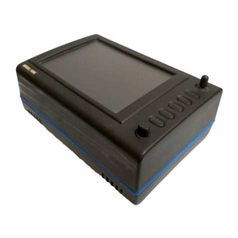
BENDIXKing Skymap IIIC User manual

BENDIXKing
BENDIXKing AV8OR User manual

