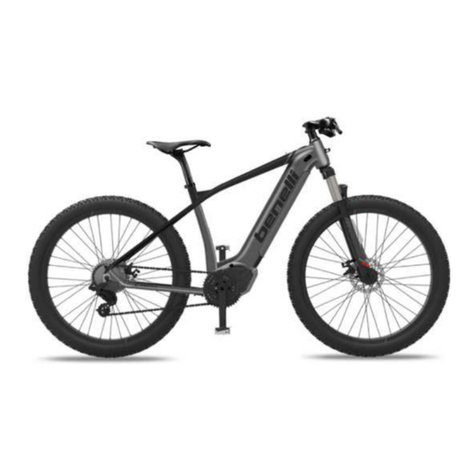
Benelli Classic User manual

1
USER
MANUAL

2
IMPORTANT:
This manual contains important safety, performance and service information. Read it before you
take the first ride on your new bicycle, and keep it for reference.
Dear Customer,
In purchasing this bicycle you have chosen a product of high quality and
technology. Each component of your new bicycle has been designed,
manufactured and assembled with great care and expertise.
These operating instructions contain a wealth of information on the
proper use of your bicycle, its maintenance and operation as well as
interesting information on bicycle design and engineering. Please read
these instructions thoroughly. We are sure that even if you have been
cycling all your life you will find useful and detailed information.
Bicycle and pedelecs technology has developed at a very rapid pace
during recent years. Therefore, before setting off on your new bicycle, be
sure to read at least the chapter “Quick start “first.
The individual steps are subsequently explained in detail, supplemented
by illustrations and diagrams.
For more detailed information on your Pedelecs, refer to “Technical data”.
Even a manual as big as an encyclopedia could not describe every
possible combination of bicycle models and components or parts on the
market. These operating instructions therefore focus on your newly
purchased bicycle and standard components and provide useful
information and warnings.
When doing any adjusting or servicing, be aware that the detailed
instructions and information provided in these operating instructions only
refer to this city/trekking bicycle or pedelecs
The information included here is not applicable to any other bicycle
type. As bicycles and pedelecs come in a wide variety of designs with
frequent model changes, the routines described may require
complementary information. Comply also with the instructions of the
parts manufacturers, which you can find on the enclosed CD.
Be aware that these instructions may require further explanation,
depending on the experience and/or skills of the person doing the work.
For some jobs you may require additional (special) tools or
supplementary instructions. This manual cannot teach you the skills of a
bicycle mechanic.
This manual cannot teach you how to ride. Please be aware that cycling
is a hazardous activity that requires the rider to stay in control of his or
her bicycle at all times.
Like any sport, cycling involves the risk of injury and damage. Keep this
in mind. When you decide to ride a bicycle or pedelecs you need to accept
the risk inherent to cycling.

3
Warning:
This symbol indicates an imminent risk to your life or health, unless you
comply with the corresponding handling instructions, given or take
preventive measures.
Caution:
This symbol warns you of incorrect actions that could result in damage
to property and the environment.
Note:
This symbol provides you with information about how to handle the
product or refers to a passage in the operating instructions that deserves
your special attention.

4
Content
Ⅰ. Mechanism
Ⅰ-1 Derailleur
Ⅰ-2 Stem
Ⅰ-3 Direction Adjustment of Front Wheel
Ⅰ-4 Brake
Ⅰ-5 Seat, Seat Post
Ⅰ-6 Tyre
Ⅰ-7 Bag Strap
Ⅰ-8 Battery Holder
Ⅰ-9 Pedal
Ⅰ- 10 Vehicle folding
Ⅱ. Electrical Equipments
Ⅱ-1 Instruments
Ⅱ-2 Electric Motor
Ⅱ-3 Battery Charger
Ⅱ-4 Battery
Ⅱ-5 Electric Schematic Diagram of Whole Vehicle
Ⅱ-6 Wiring Schematic Diagram of Sensor
Ⅱ-7 Wiring Schematic Diagram of Instrument
Ⅲ. Examination & Maintenance
Ⅳ. Appendix
Ⅳ-1 Common Sense of Use
Ⅳ-2 Driving Strategies
Ⅴ. Quality Warranty

5
CLASSIC
Whole Vehicle Mark
1. Motor
2.
T
ire
3. Rim
4. Front fork
5. Brake
7. Stem
8. Handle bar
9. Bell
10. Saddle post clamp
11. Saddle post
13.Rear rack
14.Fender
15. Rear reflector
16. Spoke
17.internal
brake
18. Chain cover
19.Chain
20.Crank
21. Pedal
23.Derailleur shifter
24. Brake lever
25.Displayer
26.Frame
27.Battery
6. Front light 12. Saddle Derailleur and roller 22.Hand grip 28.Bell
Product Definition: Power Assisted Two-wheeled Vehicle
Power Assisted Two-wheeled Vehicle is working with continuous rated power of 0.25KW and the
electric power will gradually recede to out of battery when the speed reaches 25km/h or when rider
stops cycling pedal action.

6
Ⅰ. Mechanism
Ⅰ-1. Derailleur
1.Installation of the sprocket to the hub
Place right hand dust cap C onto the driver on the right side of the hub body. Next, install the sprocket and secure it in place
with the snap ring.
2.Installation of the cassette joint to the hub
Install the driver cap to the driver to the right side of the hub body. Next, turn the cassette joint pulley in the direction of
the arrow so that the yellow mark “ ” is aligned with the yellow mark“ ”, and then align the yellow marks“ ”on
the
cassette joint with the yellow marks “ ”on the right side of the hub body.

7
3. Secure the cassette joint to the hub with the cassette joint fixing ring. When installing the cassette joint fixing ring, align
the yellow mark “ ” with the yellow mark “ ” on the cassette joint pulley.
After installing the cassette joint fixing ring, turn it 45 clockwise.
4. Installation of the hub to the frame
4.1 Mount the chain on the sprocket, and then set the hub axle into the fork ends.
4.2 Place the non-turn washers onto the right side and left side of the hub axle. At this time, turn the cassette joint so that
the projecting parts of the non-turn washers fit into the grooves of the fork ends. If this is done, the cassette joint can be
installed so that it is almost parallel to the chain stay.

8
4.3. Take up the slack in the chain and secure the wheel to the frame with the cap nuts.
4.4 Fix the brake arm securely to the chain stay with the brake arm clip.
Note:
When installing the brake arm clip, securely tighten the clip screw while holding the clip nut with a 10 mm spanner.
After installing the brake arm clip, check that the clip screw protrudes about 2 – 3 mm from the surface of the clip nut.
Brake Arm Seat on Back
Fork of the Vehicle Frame
4.5 Before using the Coaster Brake, check that the brake works properly and that the wheel turns smoothly a

9
Ⅰ-2. Angle & Height Adjustment of Stem
Ⅰ-2.1 Angle Adjustment of Tool-adjustable Stem
Loosen adjusting screw anticlockwise with internal hexagonal wrench, and then adjust the angle. Handlebar can be
adjusted to proper angle by loosing lock screw.
Ⅰ-2.2
Hor izontal A ngle
&
Height Adj ustm en t of
Tool-adjustable Stem
Take out the rubber plug,Insert a 5mm internal hexagonal wrench in the hole to loosen the tightened front fork
anticlockwise. Loosen the bolt according the aforesaid method, hold the handlebar by two hands and turn the handlebar
left and right as well as lift it higher or lower to get the proper height. After finishing the procedure, tighten it
clockwi
se.
Ⅰ-3. Direction Adjustment of Front Wheel
Make stem in horizontal and adjustable status as above. Face the vehicle and stand right in front of the vehicle. Hold the
front wheel by two legs and turn the handlebar. Adjust the center of front wheel vertically to the center of handlebar.
Ⅰ-4. Brake Adjustment
Ⅰ-4-1. V-brake Adjustment
The city bike uses the European style of the brake system. The left brake lever is for the front wheel while the right
for rear wheel.
For the adjustment or replacement of brake shoes.the 4 next steps must be followed:
1. Reposition the cable in the brake fork.
2. The shoe must be aligned with the flank and must not rub against the tire.
3. The shoe must be slightly inclined according to the angle of rotation of the wheel.
4. The distance separating the brake from the flank must be 3 to 4mm. the cable tension can be adjusted to obtain
this spacing which can also be modified by the brake handle regulator or the brake caliper regulator.
On most brake calipers there is an adjustment screw which allows the balancing of this space.
Attention! Observe the tightening schedule ( see tightening schedule chart )
Hint! When adjusting the shoe balance the wheel must be correctly positioned in the fork or the rear stems. Avoid all
contact between the shoe and the tire.
Important

7
Brake pad wear limit: replace the brake pads before the friction material has been worn down to less than 2.5 mm.
1.Open the brake lever and place the nipple end of the short brake cable into the lever, then close the lever. Secure
the ferrule against the lever using the cable adjusting barrel.
2.If fitted with V-Brakes, insert the brake body into the center spring hole in the frame mounting boss, and then
secure the brake body to the frame with the link fixing bolt.
3. While holding the shoe against the rim, adjust the amount of shoe protrusion by interchanging the position of the
B washers (i.e. 6 mm and 3 mm) so that dimension A is kept at 39 mm or more.

8
alance with the spring tension adjustment scre
4.While holding the shoe against the rim, tighten the shoe fixing nut.
5. Pass the inner cable through the inner cable lead. Set the cable with a clearance of 1mm between each brake pad
and the rim, tighten the cable fixing bolt.
6. Adjust the b ws.
7. Depress the brake lever about 10 times as far as the grip to check that everything is operating correctly and that the shoe
clearance is correct before riding the bike.

9
It is important to become familiar with the use of hand brakes. When properly adjusted, hand brakes are an efficient
braking system. Keep the rim and brake shoes clean and free from wax, lubricants and dirt at all times. Keep brakes
properly adjusted and in good working condition at all times.
Check your Brakes
Press each brake lever to make sure that there is no binding and that the brake pads press hard enough on the rims to
stop the bike. The brake pads should be adjusted so they are 1 mm to 2 mm away from the rim when the brakes are
not applied. Brake pads should be centered on the rim and “toed-in” so the rear portion of each brake pad is about
0.5 - 1.0 mm farther from the rim than the front portion of the brake pad.
Ⅰ-5. Cushion Adjustment
1. Loosen the lock bolt to adjust cushion angle with a 5mm internal hexagonal wrench as shown in the figure. Range of
adjustment is -15°~15°.
Note: it is commonly better to adjust the cushion horizontally to the ground line.
2. As shown in Figure 1, loosen the lock bolt with a 5mm internal hexagonal wrench to adjust cushion height to a proper
position. If a quick-release seat post clamp is used, pull the quick-release lever only.
Hint: What is proper height? Heel can be freely put on pedal with leg straight. When cycling pedal action is done, knees can
be slighted bent (show in Figure 3). Feet can touch the ground without standing.
Note: When adjusting seat post upwards, safety line cannot be exceeded. Safety line (11111111) should be in the frame
tube (as Figure 2).
T
ightening torque of seat post clamp should not be less than 18N.m

10
Figure 1 Figure 2
Figure
3
3. Cushion with Shock Absorption/ How to adjust soft or hard effect of shock absorption Rotate to loosen the bolt of seat
post clamp and pull the whole seat post out according to Article 2. Rotate the bolt with 8mm internal hexagonal wrench
anticlockwise to make the shock absorption softer and clockwise to make it harder.
I-6. Tyre
1. Check whether rim is deflected or loosened and whether spoke is loosened or broken before riding. If any unusual
condition, ask professional technician for adjustment or change.
2. Please change the tyre if cover tyre grain is worn and torn.
3. Please guarantee proper PSI. When inflating, please take nominal value of cover tyre as reference. Never inflate over the
pressure or under the pressure.
Caution: Please make sure the contact area of tyre and ground should not be less than 10cm while riding.
I-7. Disassembly of Elastic Band on Rear Rack

11
As shown in the following figure, grab the plastic buckle and push it downwards to release the fastener.
I-8. Battery Holder
Batteries Installation: open the lock of the battery box, support the side of the battery box , and pull it out (as left picture);
Remove the battery out: put down the end of the battery box aligned to the card slot, and then press down the end handle,
and then lock (as right picture).
Charging the position: To connect the charger interface in this location.
I-9. Change of Pedals

12
Left pedal and right pedal should be clarified when changing. Pedal spindle is usually engraved with “R” and “L”.
Tool: 15mm open end wrench
When changing Right side, clockwise rotation is to lock and anticlockwise rotation is to disassemble.
When changing Left side, clockwise rotation is to disassemble and anticlockwise rotation is to lock.
Tightening torque should be more than 18N.m
Ⅱ. Electrical
Equipmen
ts
Ⅱ-1. Instruments
Twist Shift type displayer (LCD)
The use of the turning handle type LCD instrument
1. Description of the Parts see Picture 1:
①Battery Power indicator ;
②Power-assisted level indicator;
③Speed
④Mileage
⑤Hidden magnetic switch button;
⑥Power shifting handle
Picture 1 Picture 2
2.Power on / off
Use the magnetic key to stay hidden magnetic switch button ⑤at about 5 seconds, it will turn on the
electric system; then LCD displayer is lit. After use, when you need to switch off, use the magnetic key
to stay about 5 seconds at the hidden magnetic switch button ⑤, the hidden magnetic switch button
will turn off the electric system; then all the instrument lights will turn off. Be sure to pay attention:
after the hidden magnetic switch works, please remove the magnetic key in time, to avoid switching
repetitive movements.
3.Power display
After the power on, the battery power display window ②will show automatically; When the battery is
fully charged, the four black stripes will be showed; in the vehicle riding electric assist mode process,
with the consumption of electricity, the four display lights will be one by one extinguished. When the
third light goes out, the vehicle power deficit needs to be charged, suggest to turn off the power assist
system in time. Special tips: with the increasing using frequency, the battery capacity will be gradually
reduced, and the user will be required to gradually reduce the estimate of the remaining capacity.
4. Speed display
After the power on, the battery power display window ③will show automatically. when the bike does

13
not move ,it will show zero. Along with the mobile speed ,The displayed value increase.
5. Mileage
After the power on ,The Mileage display window ④will show the bikes have distance.
Attention: The range of maximum display of the Mileage display window is 999 kilometer. when
reach maximum display, it starts from zero to display.
6.Power assisted level adjustment
The power assisted level automatically at 1 level (the lowest power level). After switch on the power,
when the rider encounters against the wind, uphill, physical decline, the power assisted level can be
raised; the specific approach is: hold the shifting handle ⑥forward and turn softly and quickly to
touch the front stopper, it will raise a power-assisted level, and the corresponding power-assisted level
light will turn on; Repeating the operation once the power assisted level continue to rise one level until
the most top grade the fourth level. If necessary, the user can downward shift the shifter, the specific
approach is: hold the gear turning handle⑥backward and turn softly and quickly, to touch the rear
stopper, it will reduce the power level, then the original power assisted level indicator light will goes
down; Repeating the operation once the power assisted level position continue to turn one level until
the lowest level change to the 1 level. Attention: after adjusting the power assisted level, let the
shifting gear turning handle reset, to avoid the repeat action, to the adoption of the high sensitive
magnetic switch, users only need to use slight force to turn the turning handle; if use the strength
force to turn over the stopper, the switch will be damaged.
7.The use of the front and rear lights
The front light: when the customer uses the front light at the first time, need to draw out the plastic
sheet of the front light. Press down the button of the front light, the front light can be turned on or off.
The front light uses the small pieces of dry batteries, please always pay attention to promptly replace
the battery power.
The rear light: the rear light turns on or off according to the electric system. The rear light uses the
battery’s power.It is no need to replace the battery. When riding at night, even if the power is loss of
electricity, also suggest do not shut off the system to ensure that the rear light is lit, to ensure the
safety of riding.
Ⅱ-2. Electrical Motor
1、Technical Data
Electrical Motor
Mode
24V
36V
Rated
Voltage
24V
36V
Rated
Current
﹤
10.5
﹤
6.95
Rated
Power
350W
350W
Rated
Efficiency
﹥
75%
﹥
75%
Idling
Current
﹤
0.95A
﹤
0.8A
Idling
Speed
220±10RPM
235±10RPM
Highest
Speed
25km/h
32
km/h
Maximum
Torque
15N*M
15N*M
Phase
Angle
120°
120°
Certification
CE
CE

14
Ⅱ-3 Technical indicators and structural of Changer
External Dimension of Electrical Motor & Diagram of Coil-out
Ⅱ-3-1. Technical Data
Charger
Mode
MDA11542002000
MDA10129402000
Temperature
of
Working
Environment
room temperature < 37℃
Input
Voltage
AC100-240V; 50HZ/60HZ
Rated
Voltage
36V
24V
Current of
Constant–current Charge
1.8--2.0A±5%
1.8--2.0A±5%
Voltage of
Constant–voltage Charge
42V
29.4V
Terminal
Current
250mA
250mA
Idling
Voltage
42V
29.4V
Weight
0.8Kg
0.8Kg
Ⅱ-3-2. Charge Curve Graph

15
Ⅱ-3-3. Structure Diagram of Charger
Ⅱ-3-4. Method of Application
1.1 When charging, connect output plug ③of the charger to charging port ⑤of the battery unit and connect transfer
port ②to ④. Then connect attaching plug ①to indoor power.
1.2 Charger adopts smart regenerative charging with constant current and voltage. According to different depths of
discharge, battery can be fully charged within 4-6 hours. Although charger will stop working when battery is fully charged, it
is suggested to take off the charger. When battery is fully charged, the attaching plug should be first torn off, then pull the
output plug of the charger.
1.3 Attaching plug of the charger should be pulled out when the charger is not used or the charging action is done.
1.4.1 “Charging” Indicator Light. When it is normally charged, the charging indictor light is “red”. When the light is “green”,
it represents the battery is charged and can be put into use.
Ⅱ-3-5. Maintenance & Attentions:
2.1 Charger should be used with designated battery strictly according to requirements. It is forbidden to charge
non-original battery with this charger.
2.2 Charger is dangerous due to the high voltage it contains. If any faults or failures are found, please contact the dealer
or the manufacturer for help. User or non-professional servicemen of the Company are forbidden to open the charger.
2.3 Charger and battery should be in indoor environment with good ventilation and heat dissipation when charging.
Places within 1m around battery and charger should be free of inflammables. Never use the charger in the environment
which is with moist, high temperature, inflammables and explosive gas.
2.4 Never take the charger along with the vehicle so as to avoid damage caused by vibration.
2.5 Carefully read the contents before application. Manufacturer assumes no liability or responsibility for any damages
caused by misuse of abnormal operation.
Ⅱ-4. Technical Data & Structure of Battery
Ⅱ-4-1. Technical Data
Specification
Data
36V
24V
Rated Voltage
36V
24V
Charging Voltage
40.15V±1%
31.5V±1%
Charging Current
2.0A±5%
2.0A±5%
Maximum
Discharging Current
2C(C is battery capacity)

16
Charging Method
smart regenerative charging
Battery Indicator
5-section LED battery indicator 100%—20%
Weight
5.3Kg
3.8Kg
Ⅱ-4-2. Product Application
1. Battery Charging
Battery should be charged timely after riding the power assist vehicle. Lithium battery of the Company should be charged
with designated charger. Connect the output plug to the charger and then connect the charger to 220V alternating current
power supply. Battery can be used after charging 6-7 hours until the charging indicator light turn from red to green.
2. Battery Discharging
Riding process of the power assist vehicle is the process of battery discharging. Users are not permitted to over
discharging the battery. Over discharging may cause severe damage to battery life. When instrument displays that the
battery is under voltage, the controller will stop power supplying at any time.
3. Battery Storage & Additional Charging
Reserve of electricity will somewhat lose when storing or during the transportation process. Battery should be
add
itional
charged before use. Charging method is as above.
4. Battery Use, Maintenance & Attention
4-1 Never put battery close to heat source of high temperature;
4-2 Charging environment is better to be below 37℃;
4-3 Avoid charging under direct sunlight;
4-4 Resolutely use designated charger to charge the battery;
4-5 Short circuit is not allowed at battery charge port;
4-6 Never put battery in wet places or in water;
4-7 Never randomly dismantle the battery or do any unauthorized modification;
4-8 Never impose external forces on the battery or drop it from high places;
4.9 When battery is not in use, it should be fully charged and stored in a dry and cool place. Places within 1m around the
battery should be free of inflammables and is insulating. Battery should be kept away from heavy load and the children.
Complete additional charging should be conducted every 2 months.
5. Warranty Period: 2 years since the date of leaving factory.
Special Warn:
○
1. Never clean the vehicle with hydraulic monitor which may cause damage to electrical components
due to water intake.
○
2. If the product smokes or burns when damaged by external forces, put it out with dry-chemical fire
extinguisher or sandy soil.
○
3. Although lithium battery is environmental friendly product, it also contains various kinds of
chemical substances. When it is broken due to aging, it may pollute the environment. Therefore,
please discard it as useless within 36 months since the date of purchase, and give it to skilled
company for professional treatment.
5. Disclaimers of Manufacturer
a. no responsibility for any damages caused by nonconforming the requirements in application instruction;
b. no responsibility for any damages caused by any unauthorized modification
c. no responsibility for any damages caused by force majeure.

17
Ⅴ.Quality Guarantee
1. In accordance with the contents of the guarantee, you can enjoy the original quality assurance and after-sales
service.
2. Apply for a free repair, held this warranty, the bicycle with you, directly contact to the original purchase store.
3. There is a frame number of all the company’s products, for product traceability and sales advice.
4. Please keep this guarantee safely, if lost will not be entertained.
*If past the warranty period for free repairs, if your bicycle need to be repaired, please contact any store, they will be
happy to serve you, but need to charge the cost fee and the wages.
*The warranty period and the conditions list in this guarantee only provide free service from morning till night, and
does not burden any legal obligation
This manual suits for next models
3
Other Benelli Bicycle manuals

