Liteville 301 Mk14 User manual

MANUAL
Compatibilities, Assembly & Maintenance

A. Delivery contents 4
B. Usage as intended 4
C. Compatibilities 5
1. Suspension Forks 5
2. Damper 5
3. Wheel size 6
4. Tire width 6
5. Hub installation measurements 6
6. X-12 through axle 7
7. Bottom bracket /crankset 7
8. Drivetrain 8
9. Rear derailleur hanger and rear derailleur 8
10. Front derailleur 8
11. Shift cable housing 8
12. Brakes 8
13. Seatpost 8
14. Seatpost reduction shims 9
15. Seat post clamp 9
16. Headset 9
D. ASSEMBLY 10
1. Frame preparation 10
2. Seatpost/seat 10
3. Headset/ fork 10
4. Handlebar/ stem 11
5. Shift and brake levers 11
6. Bottom bracket /crankset / front and rear derailleur 12
7. ServicePort 12
8. Cable routing 13
9. Cable routing front derailleur 13
10. Cable routing rear derailleur 14
11. Exchanging the housing of the rear derailleur 14
12. brake hose routing 15
13. Variable seatpost 17
14. SCS-III EVO6 chain guide 17
15. RockGuard SL 17
16. Damper preload adjustment 18
17. Damper rebound adjustment 18
E. MAINTENANCE AND CARE 19
1. Frame bearings and headset bearing 19
2. Screws 19
3. WorksFinish surface 20
4. Linkage bar overview 20
TABLE OF CONTENTS
REGISTRATION & WARRANTY
In order for us to help you efficiently in case of an accident (with a repair, a warranty
case or a general service) you should register your bike. This way, you also automati-
cally extend the warranty of your Liteville to
10 years.
Please find our entire warranty policy and information on the registration in the war-
ranty & voucher leaflet attached.
Further information on your Liteville can be found here:
http://www.liteville.com/en/72/faq-support/general/
Please find the latest updates of your 301 manual here:
http://www.liteville.com/en/77/faq-support/manuals/
As of March 2018

- 4 - - 5 -
A. DELIVERY CONTENTS
11pcs. Liteville Bicycle user manual
21pcs. polish pad WorksFinish frames
31 pcs. RockShox manual
41 pcs. Liteville 301 sticker WorksFinish
frames #130050
51pcs. VarioSpin top cap
61pcs. baseplate cone 1.5 #127159
71pcs. topplate cone 1 1/8 #127166
83pcs. cable inlet double #127517
93pcs. screw cable inlet #127487
10 2pcs. cable inlet closed #127494
11 2pcs. cable inlet single #127500
12 1pcs. cable pulley assembly tool
13 1pcs. cable tie 140x3,6mm
14 2pcs. cable tie 92x2.4mm
15 1pcs. derailleur hanger Typ3 Std #128118
16 3 pcs. foam tube #141209
B. USAGE AS INTENDED
There is no restrictions for your Liteville 301 Mk14
frame as to the maximum rider weight or the
range of usage of the bike, however you need to
assure that all components are compatible with
the frame and that they are mounted according to
the manufacturers’ manuals.
Additional components such as electric motors
may only be mounted after they have been
approved by Syntace or Liteville.
C. COMPATIBILITIES
1. Suspension Forks
Suspension forks may be mounted with a ma-
ximum insert length of 572mm. Double crown
forks must not be mounted.
The same counts for Boost- and B+ forks with a
maximum insert length of 572mm.
Make sure that the fork – when fully compressed
– does neither interfere with the steering tube nor
with the down tube.
Picture: Clearance down tube
Picture: Clearance steering tube
2. Damper
The 301 Mk14 comes with the following dampers:
• Frame lengths XS & S:
RockShox Deluxe RT3 185x 55mm
DB 1T LL S320 Trunnion
• Frame lengths M - XXL:
RockShox Deluxe RT3 205x 65mm
DB 1T LL S320 Trunnion
The front end of the damper is equipped with a
needle bearing as standard.
The installation dimension for the rear damper
socket is 54mm Trunnion.
The installation dimension for the front damper
socket is 25x8 mm.
ADVICE: The 301 frame features special
kinematics that do not harmonize ideally
with all dampers available on the market. In
order to achieve an ultimate damper setup,
our dampers are adapted accordingly.
Professional and particularly competitive riders
will be able to order an optional RockShox or
Fox damper.
Find further information at www.liteville.de
The maximum air pressure for the main damper
cartridge of the RockShox Deluxe RT3 damper
is 325 PSI (approx. 22 bar). Please use suitable
damper air pumps only.
NOTE: The RockShox Deluxe damper of a
Liteville frame features a special adjust-
ment lever. The original RockShox adjust-
ment lever must not be used since it would
interfere with the seat tube when in the
position “lock”. When different dampers
are mounted, the clearance throughout the
entire damper travel is to be rechecked in
advance.
1
2 3
4
5
6
15
16
8
9
10
11
7
12 13 14

- 6 - - 7 -
3. Wheel size
Depending on the frame length, your Liteville 301
is compatible with different wheel sizes:
• frame length XS: 26“ ( 27,5“ is possible
only with a limited tire width)
• frame lengths S, M, L, XL: 27,5“
• frame length XXL: 29“
4. Tire width
At the chain stay, the 301 Mk14 leaves a clearance
of about 77mm, which results in the following tire
width recommendations:
• frame length XS:
26“ up to 2,5“ width (27,5“ leads to a
limited width of about 2.35”)
• frame lengths S, M, L, XL:
27,5“ up to 2.6“ width
• frame length XXL:
29“ up to 2.4“ width
Using different tire widths, make sure that the
tire may touch the seat tube only slightly when
the damper is fully compressed. This also varies
depending on the tire pressure. Also mind the
restrictions as declared by the fork manufacturer.
ADVICE: In case the tire touches the seat
tube slightly, this does not result in anything
but minimal scratches on the frame and
is nothing to be worried about. However,
please also mind the restrictions as
declared by the fork manufacturer.
5. Hub installation measurements
The Liteville frame is compatible with all rear
hubs with the 148x 12 mm axle standard. We
recommend not to use adapter solutions.
ADVICE: The Liteville 301 is designed with
the EVO6 rear frame standard. An EVO6 rear
wheel, in comparison to a Boost 148mm
rear wheel, features a different spoke
pattern that allows for a fully symmetrical
and thus more stable rear wheel thanks to
identical spoke tensions on both sides.
6. X-12 through axle
The Liteville 301 Mk14 is designed with the X-12
through axle design with a width of 148mm. The
thread pitch is M12x1 mm. The Syntace X-12
through axle design – as the only solution on the
market – allows for the toe adjustment and thus
for an even more precise production of the frame.
The clamp thread (Allen Key, 5mm) in the right-
hand end of the construction is meant exclusively
for the fixation of the rear derailleur hanger as
well as for the axle insert. It does not have to be
opened when the axle or the rear wheel is re-
moved.
ADVICE: The axle insert is adapted individu-
ally to your frame and marked respectively.
The 0.5mm or 1.0 mm insert is aligned
correctly if the notch of the clamping system
and the one of the dropout is parallel.
The picture displays the insert and the clamping notch
aligned correctly.
7. Bottom bracket /crankset
The bottom bracket shell of the Liteville 301
Mk14 measures 73mm and fits common BSA
bottom brackets. ISCG adapter solutions can not
be mounted. The 301 frame is designed for one-
and two-speed Boost cranksets with a minimum
Q-factor of 167mm. 3-speed cranksets can not be
mounted.
NOTE: Mounting a SRAM DUB bottom bra-
cket, you will need the ParkTool BBT-79.
For other cranksets, please mind the clearance
between the crankset and the frame. Find
further information in the chapter “Bottom bra-
cket/crankset/ front and rear derailleur”.
Picture shows Boost SRAM
Picture shows Boost Shimano
CHAIN LINE:
SRAM 1- and 2-speed: 52mm
Shimano 1-speed: 53,4mm
Shimano 2-speed: 51,8mm
CHAIN RING SIZES:
SRAM 1-speed: 26 to 40 teeth
Shimano 1-speed: 30 to 34 teeth
Shimano 2-speed: 24 to 38 teeth

- 8 - - 9 -
8. Drivetrain
The Liteville 301 Mk14 frame is designed for one-
and two-speed drivetrains.
9. Rear derailleur hanger and rear derailleur
The 301 Mk14 comes with the rear derailleur
hanger “Type 3” with two different options. Both
the Standard and the Direct Mount versions are
included.
Type 3 Standard rear derailleur hanger for Shimano Shadow
and Sram
Type 3 Shimano Direct Mount rear derailleur
SRAM rear derailleurs are to be mounted with the
Type 3 Standard rear derailleur hanger.
10.Front derailleur
The frame is built in a way that only low Direct
Mount two-speed front derailleurs with “front
pull” designs can be mounted.
EXAMPLES:
Shimano XT: I-FDM8020E6X
Shimano XTR: I-FDM9020E6X
SRAM: FD GX LD 2X11 FRONT PULL
12.Brakes
Your Liteville 301 Mk14 is designed exclusively for
disc brakes.
The frame features a 7”-Postmount socket for the
rear brake. For 180mm discs, the brake can be
mounted directly without an additional adapter.
Disc diameters may vary between a minimum of
180mm and a maximum of 203 mm.
13.Seatpost
The inner diameter for all Liteville seat tubes is
34.9mm. The Mk14 is prepared for the usage of
an Eightpins variable seatpost. Conventional
seatposts with inner cable routings can be
mounted, too.
NOTE: The geometry of the 301 Mk14
requires seatposts with a -26 mm seat
offset. In case a seatpost without a setback,
the seat angle and the top tube length are
altered.
In order to avoid frame damages, the following
minimum insert lengths need to be considered:
Up to 200mm above seat clamp:
minimum insert = 120mm
More than 200mm above seat clamp:
minimum insert = 140mm
he length is measured from the seat clamp to the
top end of the seat cover.
11.Shift cable housing
Use nothing but shift cable housings with an outer
diameter of 4mm such as Shimano SIS-SP41.
14.Seatpost reduction shims
Using reduction shims, the minimum insert
length is still to be minded.
ADVICE: In case of doubt, choose the longer
reduction shim and mind both the compati-
bility and the quality of it (for example
Art. #113299 Syntace Post Shim Light 31.6
Art. #114203 Syntace Post Shim 30.9).
NOTE: In case the minimum insert length of
120mm or 140 mm can not be realized, the
PostShim 30.9 (Art. #114203) is to be used.
This is the only way the minimum insert
length can be reduced to 90 mm.
15.Seat post clamp
If you mount a conventional seatpost or common
variable seatpost other than Eightpins, we
recommend you to use a Syntace SuperLock2
or MicroLock38 seat clamp. In case you want
to use a different seat post clamp, it is to fit the
outer seat tube diameter of 38mm and must
not interfere with the linkage bar of the damper
system when it is fully compressed. In order to
reaffirm this, deflate the damper entirely and
move the rear frame triangle upwards.
16.Headset
The Liteville 301 Mk14 comes with a 0° Syntace
VarioSpin headset as standard. In order to adapt
the frame to the rider’s individual requirements,
one can mount +/- 1.5° bearing shells as an
option. The latter are displayed in blue.
Steering tube angle +1,5° Steering tube angle -1,5°
XS S M L XL XXL
cup
set 2
cup
set 2
cup
set 3
cup
set 4
cup
set 6
cup
set 3
Art.No.
114944
Art.No.
114944
Art.No.
114890
Art.No.
114906
Art.No.
114920
Art.No.
114890
Find an instruction video here:
https://www.youtube.com/watch?v=NpAF1IG7fuw

- 10 - - 11 -
D. ASSEMBLY
1. Frame preparation
The contact surfaces (bottom bracket, disc brake
socket, seat tube) are fully prepared for the
assembly. In case you face problems during the
assembly, please directly contact Syntace.
NOTE: The seat tube is manufactured
particularly accurately for the Eightpins
variable seatpost with very small tolerances
only. This is why it must not be changed in
any way.
NOTE: In case the frame is painted or ano-
dized after the purchase, make sure that the
inner diameter of the seat tube remains the
same for the entire 140 mm insert length.
3. Headset/ fork
The frame comes with nothing but the cone and
the cover cap for tapered fork steer tubes
(see picture).
ADVICE: Reduction kit for 1 1/8“-fork steer
tube: Syntace Art.# 14593
Make sure all parts of the headset, including the
bearings, are greased before the assembly. Put
the bigger (1,5”) cone on the fork, which is to lay
evenly on the fork crown. The fork can now be
inserted into the frame before the smaller (1 1/8”)
cone is put on the fork steer tube. Installing the
cover cap is the last step of the headset assembly.
ADVICE: Using a Syntace MegaSpacer, a
silver 0.6 mm washer needs to be added
between the SuperSpin cover cap and the
MegaSpacer. The washer is included in the
MegaSpacer package or can be ordered
separately as a spare part at Syntace.
ADVICE: Tighten the adjustment screw of
the Ahead star nut hand-tight. Loosen it
again thereafter with about ¾ revolutions
and only in the next, last step adjust the
bearing play of the headset bearing. Follo-
wing this procedure, you make sure that the
bearings sit evenly in the bearing shells. The
result should be that the fork can be turned
easily without any bearing play. It may be
necessary to repeat the process after the
first ride.
2. Seatpost/ seat
The 301 Mk14 is designed for variable seatposts
with internal cable routing. The assembly is sim-
plified thanks to the ServicePort at the lower end
of the down tube close to the bottom bracket.
Please refer to the extra manual of Eightpins
that exemplifies the assembly process with a
Liteville 301 Mk14.
http://www.eightpins.at/service-einbau/
4. Handlebar/ stem
Mount and adjust the handlebar and stem
according to the Syntace manual.
5. Shift and brake levers
Mount and adjust the shift and brake levers
according to the manufacturers’ manuals.
ADVICE: Tighten the screws of the brake and
shift levers only so much that they can still
turn in case of a crash. This might avoid a
lever to brake apart and additionally protects
the thin walls of your handlebar.
NOTE: The standard Eightpins variable
seatpost interface (Postpin) at the seat tube
is adapted already and does not need to be
changed.
Using a common seatpost, the frequent chan-
ging of the seat height leads to a certain wear of
the seatpost and the seat tube. For carbon fiber
seatposts, this wear is considerably higher than
for Aluminum seatposts. In order to minimize the
wear, please clean the seatpost and seat clamp
after every ride in the rain. The diameter of the
seatpost must never become less than 34.7 mm
at any point. If this is the case, please exchange
the seatpost as it might result in damages of the
frame.

- 12 - - 13 -
Picture shows: Shimano side swing front derailleur
• Mount and adjust the rear derailleur according
to the manufacturer’s manual with a suitable
rear derailleur hanger (Direct Mount/ Stan-
dard).
7. ServicePort
At the lower end of the down tube, you will find
the ServicePort with which the assembly of the
bike including the internal cables is simplified.
Opening the ServicePort:
• Fixate the frame and open the ServicePort
screw with about 3.5 counterclockwise revolu-
tions.
• Open the ServicePort towards the front making
usage of an Allen key.
• You may now take the ServicePort out of the
frame.
Closing the ServicePort:
• Follow the procedure above in the opposite
directions.
8. Cable routing
NOTE: For the cable routing, we recommend
to use the Park Tool “Internal Cable routing
kit” IR-1.2 or the RockShox Barb Connector
SRAM article # 00.6815.066.030
1
2
3
The picture displays the 1Park Tool …,the 2cable pulley
assembly tool and the 3RockShox Barb Connector
The frame comes with a cable deflection pulley
in each chain stay that allows for a cable routing
free of friction resistance between the chain stay
and the rear dropout. The package includes an
assembly tool in case the deflection pulley is to be
demounted (Pos. 11).
2
1
5
4
3
Picture displays exemplified 2 x 11 drivetrain, brake and
variable seatpost housing.
1Variable seatpost
2Rear derailleur
3Rear brake
4Front brake
5Front derailleur (side swing)
9. Cable routing front derailleur
• Insert the cable in the right-hand opening
of the frame and push it all the way to the
ServicePort.
• In the next step, push it through one of the
foam tubes and pull it back slightly before
pulling the cable housing out of the front
derailleur cable opening of the frame.
• Mount the cable inlets (Pos. 10, 11) on both
sides. On the side of the front derailleur, use
a “cable inlet single” if you do not ride with a
variable seatpost, or a “cable inlet double” in
case you do.
• Attach the lower end of the cable housing to
the front derailleur.
6. Bottom bracket /crankset / front and rear
derailleur
Mount the two bearing shells and the crankset
according to the manufacturer’s manual and do
not forget to grease the system thoroughly.
NOTE: Mind the clearance between the
crank arm and the chain stay as well as
between the right-hand crank arm and the
Syntace SCS chain guide.
Picture displays the clearance between the chain stay and
the crank arm
• Mount the low Direct Mount front derailleur at
the intended socket.
• Mounting Shimano front derailleurs, use
two raised countersunk head screws
(M5x 10 mm / TX25/ ISO 7380). The Shimano
derailleur comes with the two screws as
standard or can be ordered at Syntace
(Art. #140882). For SRAM front derailleurs,
only one of these screws is needed.
• Make sure that the guide plate of the front
derailleur is parallel with the big chain ring.
NOTE: Please mind the different cable rou-
ting options of front derailleurs offered. The
Liteville 301 Mk14 is compatible with front
pull design solutions only.

- 14 - - 15 -
• Cut the new cable housing at a 45° angle and
slightly fold it. Thereafter, insert the new cable
housing above the Horstlink at the rear end of
the chain stay.
• Pull the new cable housing out of the front end
of the chain stay until the rest at the end of the
frame leading to the rear derailleur has the
right length. Turning it simplifies the process.
• Entirely slip the PE tube over the cable
housing until it reaches into the chain stay
for about 2cm.
• With a sweeping curve, the cable housing
is to be inserted into the right-hand hole of
the main frame and then pulled out of the
ServicePort.
• Simultaneously pulling and pushing, the cable
housing can now be guided through the Ser-
vicePort until the PE tube sits solidly between
the chain stay and the main frame.
• Starting at the front, slip the foam tube over
the cable housing until it reaches the inner
main frame.
• With the help of the Park Tool IR-1.2 or the
RockShox Barb Connector, the cable housing
including the foam tube can be guided through
the down tube and into the left-hand cable
hole at the top of the tube.
12.brake hose routing
In order to simplify the routing of the brake hose,
the frame comes with a shifting cable housing
inside the left-hand chain stay. The Park Tool
IR-1.2 or the RockShox Barb Connector may help
further. Refer to the picture.
brake line
RockShox
Barb Connector
50cm
threader
At first, the hose is to be cut at the brake lever.
The clamping capsule and the fitting need to be
removed.
Working with the Park Tool Internal Cable
Routing Kit:
• Connect the front end of the cable housing in
the left-hand chain stay with the threaded end
part of the routing advice.
• Towards the rear end of the frame, pull the
cable housing out of the chain stay leaving the
Park Tool routing advice inside the chain stay.
• Disconnect the advice and the cable housing.
11.Exchanging the housing of the rear derailleur
• Remove the old housing, the PE tube between
the chain stay and the main frame and the
foam tube.
Make sure the housing is underneath the cable pulley.
10.Cable routing rear derailleur
The housing of the rear derailleur has been
inserted into the frame already.
• Guide the rear end of the housing to the rear
derailleur and attach it to the intended socket
at the Horstlink using a cable tie (Pos. 14).

- 16 - - 17 -
If you assemble your bike without a Park Tool
Internal Cable Routing Kit, the procedure can be
realized with a SRAM hose connector, too. In the
end, the brake hose can be guided through the
chain stay in a similar way as with the Park Tool
advice.
The assembly of the brake depends on different
brake modals and should be realized as displayed
below.
Picture shows rear brake on a Post Mount socket with hose
routing for Shimano.
Picture shows rear brake on Post Mount socket with hose
routing for SRAM.
13.Variable seatpost
The 301 Mk14 is designed for a fully integrated
Eightpins variable seatpost. Refer to the separate
Eightpins manual that can also be downloaded at
www.eightpins.at
NOTE: The routing for all internal cable
routing variable seatposts is done via the
ServicePort in the down tube.
• Guide the cable housing or the hydraulic hose
through the right-hand hole at the steering
tube and pull it out of the ServicePort at the
lower end of the down tube.
• From the bottom end, slip a foam tube over the
hose all the way to the cable hole at the top
end of the down tube.
• Now push the cable housing or hydraulic hose
upwards – through the snorkel (see arrow) –
into the seat tube.
• Mounting a variable seat post, stick to
the recommendations of the individual
manufacturers’ manuals.
14.SCS-III EVO6 chain guide
The SCS-III EVO6 chain guide (Art. #131040) is
attached to the right-hand chain stay yoke with a
single screw.
Picture shows Syntace SCSIII EVO6 chain guide
NOTE: The SCS-III EVO6 chain guide is com-
patible only with one- and two-speed Boost
cranksets.
15.RockGuard SL
The Liteville 301 Mk14 features an interface for
the Syntace RockGuard
Art.: 116757, black
Art.: 117013, WorksFinish
Picture displays RockGuard SL in black
• Connect the threaded part of the advice to the
brake hose for the rear brake and pull it back
into the left-hand chain stay. Support the hose
and the tool by simultaneously pulling and
pushing.
• Guide the routing advice through the left-hand
hole of the main frame and from the bottom
into the ServicePort.
• Slip a foam tube over the routing advice and
the brake hose.
• With the help of the Park Tool magnet, guide
the routing advice through the down tube of
the frame and into the top end cable hole of
the frame.

- 18 - - 19 -
16.Damper preload adjustment
In order to guarantee for a perfect setup of the
RockShox Deluxe RT3, the damper is to be ad-
justed with a 30 % negative travel/ Sag of the
entire damper travel of 55 to 65 mm.
For the perfect function of the damping system of
the rear frame, follow precisely the steps below
• Find an even road
• Sit on your bike fully equipped, including back-
pack, bottle, helmet, etc. and start riding.
• Make sure the compression stage of the
damper is open (the black lever is to point
towards the right).
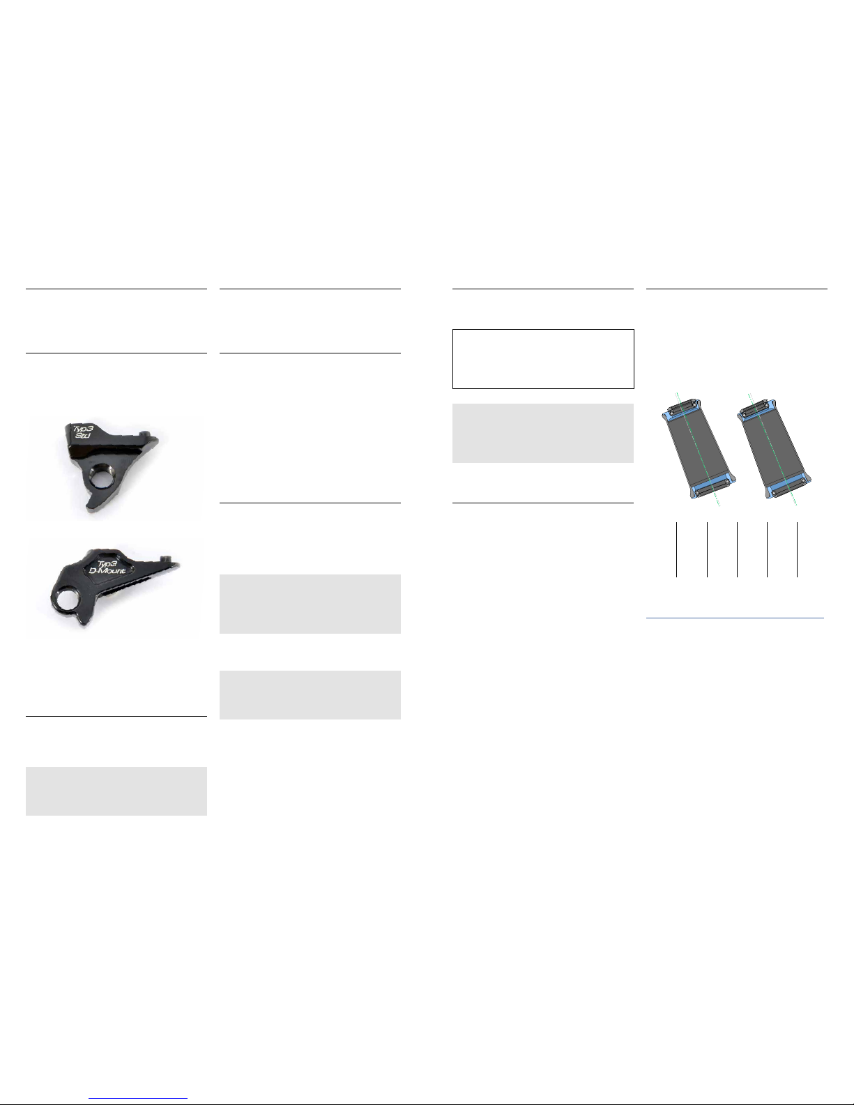
• Look downwards on the “Sag-Indicator
(dynamic level) and check the two indicator
sticks.
Picture displays dynamic level adjustment
RECOMMENDATION: the sticks should be on the
same height equaling a 30% Sag setting.
NOTE: Even a bigger backpack noticeably
increases the load on the rear wheel. Adjust
the air pressure in the damper respectively.
17.Damper rebound adjustment
Sitting on your bike, ride down a sidewalk. The
rear frame should “bounce” only once. In case
it does so more often, close the rebound of your
damper further. In case the rear frame works too
fast, open the rebound. The rear frame should
not go back into its original position too fast. This
is because it should be “prepared” for further
obstacles to come as soon as possible.
With most dampers, the direction of the adjust-
ment is indicated with a “+” or symbolized with a
“turtle”. The adjustment wheel in the middle, with
most modals, is painted red. Please additionally
refer to the manufacturers’ manuals for further
adjustment advices.
ADVICE for your damper system setup:
if you want your 140mm All Mountain 301
to become even more downhill oriented, we
have some advice for you.
For a more stable and smooth performance
riding downhill, we recommend to mount
the VarioSpin. With this option, the stee-
ring angle becomes less steep (by 1.5°)
which leads to more stability. On top of this,
the damper can be equipped with one or
even more volume spacers. The overall air
volume of the damper is reduced thereby
which alters the characteristic curve. At
the same time, the final progression of the
damper is increased. Please find further
information at the website of the individual
damper manufacturer.
E. MAINTENANCE AND CARE
1. Frame bearings and headset bearing
With conventional usage, the bearings do not
have to be dismounted, greased or cleaned. In
case a bearing gets damaged anyways, you may
order the respective bearing type at your Liteville
Worksstation and have it exchanged there or order
it at Syntace directly.
Picture shows bearings that can be greased in the top tube.
Picture shows bearings that can be greased at the HorstLink.
ADVICE: We recommend the Syntace
GreaseGun (Art. #116931) for most effective
results.
Never point at your bearings with a high-pressure
water jet, as this can easily damage them. After
all, too much “maintenance” may even harm your
bearings.
2. Screws
The screws in your frame are all made from
Titanium or Aluminum and are produced
specifically for Liteville frames. They are all
mounted with screwlock. Nonetheless, you are to
check the correct tightening torque frequently.
ADVICE: in case a screw can actually be
twisted as the tightening torque is che-
cked, the screwlock is broken and as a
consequence needs to be exchanged. The
screw needs to be secured again. Unscrew
it, clean it and reassemble everything with
screwlock.
We have summed up a “Screwlock Basics”
at www.liteville.de > FAQ.

- 20 - - 21 -
3. WorksFinish surface
The Liteville WorksFinish is a genuine raw Alu-
minum surface, free of any kind of protection
paint, meaning it is no Aluminum simulation. The
frame actually shows the signs of the original ma-
nufacturing process. Stains are thus common, the
frame may even change its color slightly which
leads to the natural charm of a grown patina.
The surface can be reprocessed at all times either
chemically or mechanically with a Scotch-Bri-
te-Finish or by being polished manually. The
frame comes standard with two Scotch-Brite
grinding fleeces. Try applying it on a spot that is
not seen directly.
4. Linkage bar overview
115
52
127
67
120
49,50
132
63
Rocker_LV-301_115-52
Rocker_LV-301_127-67
Rocker_LV-301_120-49.5
Rocker_LV-301_132-63
140 mm travel 160 mm travel
frame size:
XS, S
frame size:
M, L, XL, XXL
NOTE: The WorksFinish frame comes with
3M stickers. It is your choice if you put them
on your frame or if you do not.
Picture shows Liteville stickers.
When tightening screws, always use a torque wrench such as the Syntace Torque Tool.
Caution: in case a screw can actually be twisted as the tightening torque is checked, the screwlock
is broken and as a consequence needs to be exchanged. The screw needs to be secured again.
Unscrew it, clean it and reassemble everything with screwlock. We have summed up a “Screwlock
Basics” at www.liteville.de - FAQ.
SCREWS: MAXIMUM TIGHTENING TORQUE AND SECURING SCREWS

- 22 - - 23 -
24
22
21
19
18
20
26
3.2
3.5
3.6
3.1
3.6
3.5
3.3
9
10
17
2.2 2.1 2.1 2.2
2.3
3.4
4.2 4.2
3.4
4.4
27
4.3 4.4
1.6
4.6
1.5 1.3 1.2
33
34
36
34 35
4.3
4.7 4.1
33
8.1
16
8.3
8.4
3.3
3.6 3.1 3.6 3.5 3.2
3.5
1.1 1.1
13 12
15
11
32
28
29
32
8.2
8.5
1.6
15
14
14
15
11
15
13
12
1.2 1.4 1.3 1.5
32
30
23
25
38
38
29
28
30
28
9
4.5
31
31
31
5
2.4
2.5
2.5
2.4
37
37
6
2.6
2.7
40
7.6
7.3
7.5
7.1
7.2
7.4
39
SPARE PARTS NOTES
POS-NR.
Description
Article No.
Qtty
1
MF_LV-301_MK14_L
1
1.1
washer_BB_18x15.2x1
127944 2
1.2
NB_14x22x13_4900-2rs
114500 2
1.3
axial_washerbushing_for_NB
111691 2
1.4
TT-pivot-steel-axle for_needle_bearing_42.0mm
115149 1
1.5
washer_16x10.3x1
120013 2
1.6
NORGLIDE-bearing_13x15x6 140646 2
2
CS_LV-301_MK14_L
1
2.1
BB_15x28x7_61902-2rs_EXI
110526 2
2.2
screw_Al_M14x1x24.5_11.5t_HEX8
128200 2
2.3
screw_POM_M10x1x8_HEX5_plug
127043 1
2.4
CS-cable-pulley
130395 2
2.5
screw_M3x30
130401 2
2.6 CS-protector_top_size-3
140660 1
2.7
CS-protector_bottom
140677 1
3
SS_LV-301_MK14_L
1
3.1
Horstlink-axle_T-01
127050 2
3.2
screw_Ti_M8x0.75x11.0_HEX5_GP
120396 2
3.3
screw_Ti_M8x0.75x11.0_HEX5_plug
120389 2
3.4
screw_Ti_M8x0.75x8.5_ HEX5
103733 2
3.5
washer_Al_16x12x2
140684 4
3.6
BB_12x21x5_61801-rs
141766 4
4
Rocker_LV-301_MK14_L
1
4.1
Rocker_LV-301_132-63
128910 1
4.2
bolt_12x20x8.5_M8x0.75_HEX5
120020 2
4.3
BB_12x21x5_61801-2rs
114449 2
4.4
washer_Al_16x12x2.5
120037 2
4.5
sag-indicator_M5_T-01
127197 1
4.6
screw_Ti_ M10x1x16.3_ 10.5t_HEX5_plug
128842 1
4.7
screw_Ti_ M10x1x16.3_ 10.5t_HEX5_GP
128835 1
5
Deluxe RT3 205x65 TRST
130869 1
6
Lever_RS-Deluxe_short
140875 1
7
closing-cap_assembly_T01
1
7.1 closing-cap_63
127920 1
7.2
closing-cap_3M-sticker_T01
142305 1
7.3 closing-cap_snap-plate
145337 1
7.4
screw_VA_M5x12.5_HEX5
127937 1
7.5
washer_SS_10x5.5x1
145344 1
7.6 stop-nut_M5
145351 1
8
X-12_axle_assembly_148mm_allen-key
119017 1
8.1
X-12_axle_148mm_EVO6
127081 1
8.2
X-12_stainless-steel_washer 12mm
127098 1
8.3
X-12_axle_end-plug
127104 1
8.4
X-12_axle_cone
127111 1
8.5
X-12_axle_O-ring_small
127128 1
9
X-12_hanger_screw_Typ2_26mm
116849 2
10
X-12_thread-insert_0mm
105683 1
11
axle_SS_10x13x11
128781 2
12
screw_Ti_ M10x1x16.3_ 10.5t_HEX5
103764 2
13
o-ring-cover_ID-13
128798 2
14
o-ring-cover_ID-13_pf
141759 2
15
X-Ring_12.42x1.78
140691 4
16
X-12_hanger_Typ3_D-Mount
128101 1
17
X-12_hanger_Typ3_Std
128118 1
18
Headset-cup_1.5_57x52
127142 1
19
Headset-cup_1-1-8_48.8x41
127135 1
20
BB_40x52x7_2RS_cone
103887 1
21
BB_30x41x6.5_2RS_cone
103870 1
22
Topplate-cone_1-1-8
127166 1
23
VarioSpin-Top-seal_1-1-8
127210 1
24
VarioSpin-Top-Cap_1-1-8
127173 1
25
O-Ring_28.6x2.0
127203 1
26
Baseplate-cone_1.5_39.8
127159 1
27
screw_Ti_M8x1x44.5_ HEX5
112339 1
28
cable-inlet_double
127517 3
29
cable-inlet_single
127500 2
30
cable-inlet_closed
127494 2
31
cable-inlet_Di2
140707 3
32
screw-sc_M4x6_HEX2.5
127487 3
33
washer_POM_20x11.1x5.925
128187 2
34
O-Ring_11x3.0
110281 2
35
NB_11x15x12.7
110571 1
36
axle_SS_8x11x24.9
128217 1
37
washer_Al_16x8x2.5_EXI
140714 2
38
rubber plug cable spot DT
120006 2
39
Eightpins_postpin
143371 1
40
PostPin_adjusting-ring
140813 1

- 24 -
GmbH
Dammweg 1 · D-83342 Tacherting · Germany
Tel. +49 (0)8634 66666 · Fax +49 (0)8634 6365
syntac[email protected]
www.syntace.de
Am Mühlbach 12b · 87487 Wiggensbach · Germany
Tel. +49 (0)8370 929988 · Fax +49 (0)8370 929888
office@liteville.de
www.liteville.de
Table of contents
Other Liteville Bicycle manuals