INTENSEcycles Spider 275 User manual

user manual spider 275

AT INTENSE, WE HAVE ONE GOAL - TO PROVIDE THE RIDE OF YOUR LIFE.
Our team of designers, engineers and product experts are focused on one thing every
day: your experience on the bike. We build bikes that are as thrilling to look at as they
are to ride, and we build them for the select few of you who understand the difference
and refuse to settle for anything else.
From the early days of Intense, when founder Jeff Steber worked alone in his garage to
today, where a crew of talented people work in a Temecula, CA factory, Intense has been
a brand built on passion by forward thinkers who, even today, love nothing more than
to throw a leg over a sweet bike and head out for a rip. We’re so glad you’ve joined us.
Welcome to Intense, enjoy your experience.
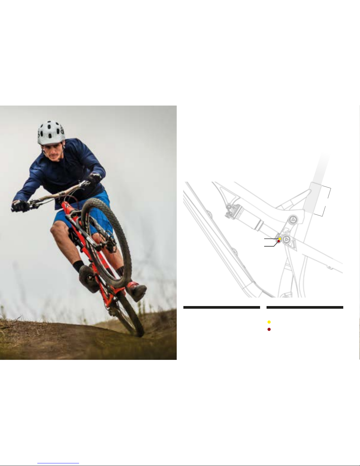
THE SPIDER 275
The Spider 275 is a ripping trail bike in the emerging 275 wheel size. Its VPP suspension
technology provides an optimized wheel path and minimal resistance whether you’re
climbing or mashing pedals on the flats. Drop your post and use up the full 5” of
rear wheel travel to clean any technical section of your favorite downhill trail. With
Intense Cycles quality, cunning frame design and time tested geometry; the Spider
275 won’t disappoint.
registration
WWW.INTENSECYCLES.COM/WARRANTY-CARD/
contact customer service
cs@intensecycles.com
951-296-9596
Welcome to
the family
2// spider 275 user Manual

introduction / registration 2
frame features / component spec 4
Geometry 5
exploded view and b.o.m. 6
Assembly 8
torque chart 13
setup 14
maintenance 18
INTENSE CYCLES // 3

4// spider 275 user Manual
frame
features /
spec
frame Features //
•Adjustable Travel: 4.5" to 5" (115mm-130mm)
•27.5” Wheel size
•Integrated 142 x 12 dropouts
•Patented VPP Suspension Technology
•7.6 lbs. Frame weight (Medium Naked)
•ISCG 05 Mounts
•Internal Seat Tube Cable Routing for dropper posts
•H20 Bottle Fitment
•FLK – GRD Downtube and Chainstay protection
•Tapered Head Tube
•Direct Mount Front Derailluer
•Angular Contact/Collet Bearing System with replaceable Grease Zerks
component spec //
•Fork – 1.5” tapered steer, 130mm Travel, 519mm lower leg length, 42mm offset
•Shock – 200mm x 50.8mm (7.875” x 2”), 22mm x 6mm and 30mm x 6mm reducers
•Front derailleur – Direct Mount
•Seat post – 31.6mm
•Headset – Cane Creek, 40, Alloy Cartridge (www.canecreek.com)
•Bottom bracket - Threaded 73mm bottom bracket
•Rear Axle – 142 x 12 T/A
•Brake Mount – international standard for 160mm rotor
•crank set - single or double ring only

INTENSE CYCLES // 5
Geometry
C
A
F
B
E
D
G
H
L
K
I
J
GEOMETRY NOTEs
GEOMETRY TAKEN AT TOP OUT WITH 519MM
FORK LENGTH AND 42MM FORK OFFSET.
Component spec NOTE
the spider 275 is designed around the use
of single or double chain ring sets only.
Use of a triple ring set will not allow
proper clearance with the frame.
SMALL MEDIUM LARGE XLARGE
AWheel Base: 1125 mm/ 44.3” 1152 mm/ 45.4” 1178 mm/ 46.4” 1203 mm/ 47.4”
BTop Tube Length: 572 mm/ 22.5” 597 mm/ 23.5” 622 mm/ 24.5” 648 mm/ 25.5”
CChain Stay Length: 419 mm/ 16.5” 419 mm/ 16.5” 419 mm/ 16.5” 419 mm/ 16.5”
DHead Tube Length: 102 mm/ 4” 115 mm/ 4.5” 127 mm/ 5” 127 mm/ 5”
EHead Tube Angle: 67˚ 67˚ 67˚ 67˚
FReach: 422 mm/ 16.6” 445 mm/ 17.5” 467 mm/ 18.4” 492 mm/ 19.4”
GStack: 579 mm/ 22.8” 591 mm/ 23.25” 602 mm/ 23.7” 602 mm/ 23.7”
HBB Height: 337 mm/ 13.25” 337 mm/ 13.25” 337 mm/ 13.25” 337 mm/ 13.25”
ISeat Tube Angle (Effective): 75.5˚ 75.5˚ 75.5˚ 75.5˚
JSeat Tube Angle (Actual): 72.5˚ 72.5˚ 72.5˚ 72.5˚
KSeat Tube Length: 375 mm/ 14.75” 445 mm/ 17.5” 483 mm/ 19” 514 mm/ 20.25”
LStandover Height: 776 mm/ 30.6” 783 mm/ 30.8” 790 mm/ 31.1” 795 mm/ 31.3”
6// spider 275 user Manual
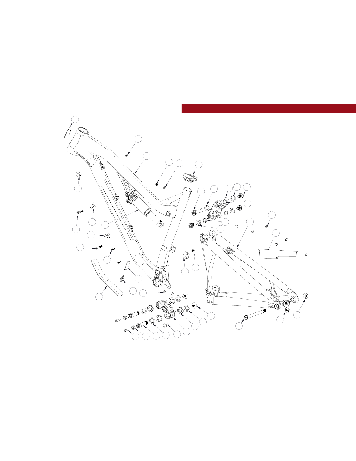
exploded view
and b.o.m.
18
16
19
16
31
33
2
27
6
27 8
34
16
29
13
1
24
9
11
7
10
22 412 5
3
26
5
14
15
30
17
28
20
21
21
16
23
16
16
25
32

INTENSE CYCLES // 7
ITEM
NO. ITEM PART
NUMBER DESCRIPTION QTY. TORQUE SPEC.
1Derailleur Mount
Cover 130209 For Single Chain Ring Setup 1N/A
2Top Link 130216 Forged Top Link 1N/A
3Box Link 130770 Forged Lower Link 1N/A
4Cone Adjuster 130777 Main Pivot Expander Cone 2N/A
5Bearing Cap 130778 Main Pivot Bearing Cap 4N/A
6Axle Upper 130780 Top Link Pivot Axle 120 Nm /
175 in-lbs
7Washer 130784 Top Link Pivot Lower Washer 2N/A
8Bolt Shoulder 130785 Top Link Pivot Bolt 320 Nm /
175 in-lbs
9Rear Axle 130786 142 x 12mm Wheel Axle Kit 111 Nm /
100 in-lbs
10 Spacer 130789 Top Link Pivot Upper Spacer 2N/A
11 Hanger 130790 Forged Derailleur Hanger 1N/A
12 Bolt Main Pivot 130791 Main Pivot
1.5t Expander Bolt Blk 27 Nm /
60 in-lbs
13 Hanger Bolt 130792 Derailleur Hanger Bolt 111 Nm /
100 in-lbs
14 Plug 140004 Box Link Pivot Plug 2N/A
15 Bumper 140006 Box Link Bumper 1N/A
16 Plastic Clip 310001 Snap-on Cable Guide Single 17 N/A
17 Cable Guide 310005 Bolt-on Plastic
Cable Guide Single 1N/A
18 Seat Collar 346940 QR 34.9 Blk 1N/A
19 Shock Bolt Nut 400009 M6 x 1.0 x 2mm 1N/A
ITEM
NO. ITEM PART
NUMBER DESCRIPTION QTY. TORQUE SPEC.
20 Zerk Fitting 401011 M6 x 1.0 25 Nm /
40 in-lbs
21 SHCS M6 x 40 410002 Shock Bolt,
Socket Head, M6 x 40 27 Nm /
60 in-lbs
22 SHCS M6 x 22 410009 Cone Adjuster Bolt,
Socket Head, M6 x 22 214 Nm /
125 in-lbs
23 BHCS M5 X 12 410010 Guide Bolt, Button Head,
M5 X 12 26 Nm /
54 in-lbs
24 FHCS M6 x 12 410037 Derailleur Mount Cover,
Flat Head, M6 x 12 17 Nm /
60 in-lbs
25 Bearing 6901 430001 12 x 24 x 6 2RS Radial Bearing 2N/A
26 Bearing 7902 430007 15 x 28 x 7 2RS,
MAX Angular Contact Bearing 4N/A
27 Bearing 6802 430008 15 x 24 x 5 2RS,
MAX Radial Bearing 2N/A
28 Guard Flack DT 500230 Flack Guard
Spider 275 Down Tube 1N/A
29 Guard Flack CS 500231 Flack Guard
Spider 275 Chain Stay 1N/A
30 Decal 500300 California Bear 1N/A
31 Head Badge 500335 Head Badge Flame Logo 1N/A
32 Shock Shock Rear Shock 7.875 x 2 1N/A
33 Front Triangle Triangle
Front Aluminum, 4 Sizes 1N/A
34 Rear Triangle Triangle
Rear Aluminum, 1 Size 1N/A
8// spider 275 user Manual
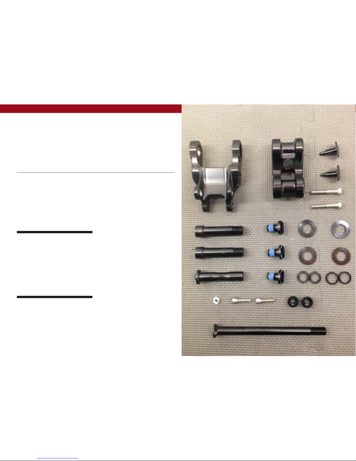
Assembly
Tools needed
•High Grade, waterproof grease
(Maxima Waterproof Grease
recommended)
•Blue Loctite #243
•5mm HEX wrench x2
•8mm HEX wrench
Recommendation
use Grease on lower linkage bolts
only. use loctite on upper linkage
bolts, dropout bolts and hanger bolt.
PREFACE //
Service and maintenance on an Intense bicycle requires special tools, abilities and
knowledge of working on bicycles. It is always recommended to use an authorized
Intense dealer for service and maintenance. Always wear eye protection. It is critical
to use the proper tools, loctite, grease and torque specs during assembly. Failure to
follow these instructions may result in serious bodily injury or death.

INTENSE CYCLES // 9
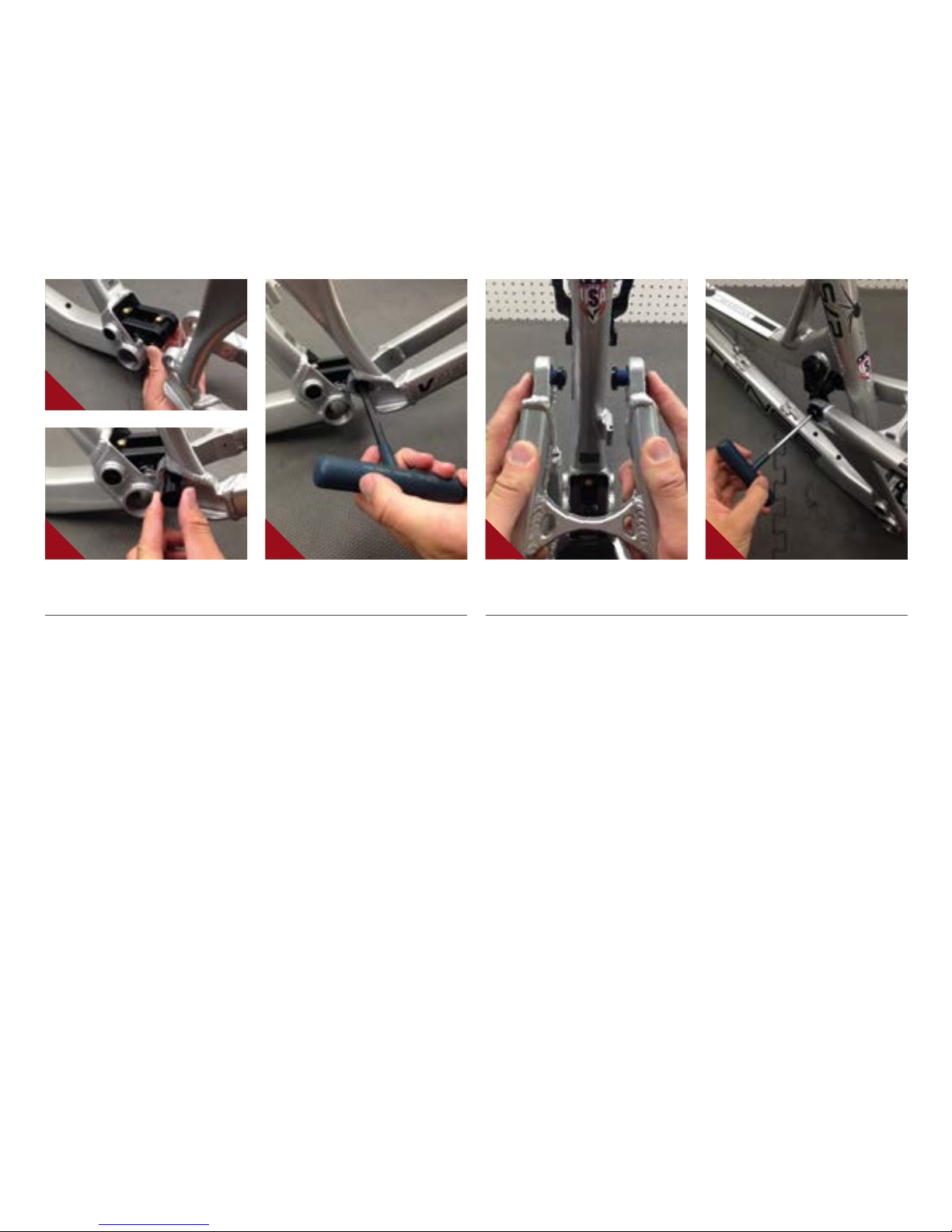
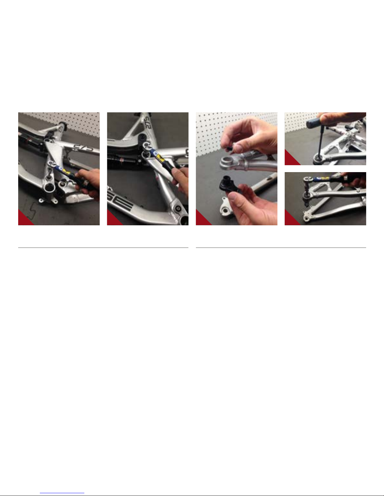
CONNECTING TOP LINK TO FRONT TRIANGLE //
AHolding top link (PART#130216) with
shock mount pointed forward; hold upper
spacer (PART#130789) against inside of
bearing race.
BMatch upper linkage to pivot point on
top tube, making sure that spacers do
not fall out (IMAGE #1).
CUsing upper pivot axle (PART
#130780), insert through non-drive side
of top link bearing and push through to
drive side bearing making sure spacers
do not fall out. Then, thread bolt into axle
from drive side using 5mm allen wrench
(IMAGE #2).
DHolding 5mm allen wrench on non-drive
side upper axle, insert torque wrench into
bolt on drive side and tighten to 125 in/lb
(IMAGE #3).
CONNECTING BOX LINK TO FRONT TRIANGLE //
AHold bearing cap (#130778) with
rounded edge facing outwards against
bearings on linkage piece (IMAGE #4).
See images and exploded view for linkage
orientation. Note that linkage will mount
to front triangle pivot point at bumper end.
BMatch link to front triangle pivot point
and insert main pivot expander bolt with
greased threads (#130791) through non-
drive side of box link, holding bearing
caps in place (IMAGE #5). Use 8mm allen
to install bolt (IMAGE #6).
1 4
2 5
3 6
10 // spider 275 user Manual
CONNECTING REAR TRIANGLE TO BOX LINK //
AFollow previous steps to connect rear triangle to box link (IMAGES #7-9).
CONNECTING REAR TRIANGLE TO TOP LINK //
AInsert shoulder bolts (#130785)
through seat stay bearings. Hold lower
top link washer (#130784) against
inside race of seat stay bearing, on top
of shoulder bolt threads (IMAGE #10).
BMatch shoulder bolts to lower top link
threads and tighten shoulder bolts to
175 in/lb, making sure that each washer
is in place between bearing and linkage
(IMAGE #11).
7
8 9 10 11
INTENSE CYCLES // 1 1
INSTALLING ADJUSTER CONES AND FINAL ASSEMBLY //
ATorque main pivot bolt to 60 in/lb
using 8mm allen head (IMAGE #13).
BGrease and insert cone adjuster
(#130777) into head of main pivot
expander bolt (#103130) with M6x22mm
bolt (#410009) inserted through cone
adjuster (IMAGE #14 & 15).
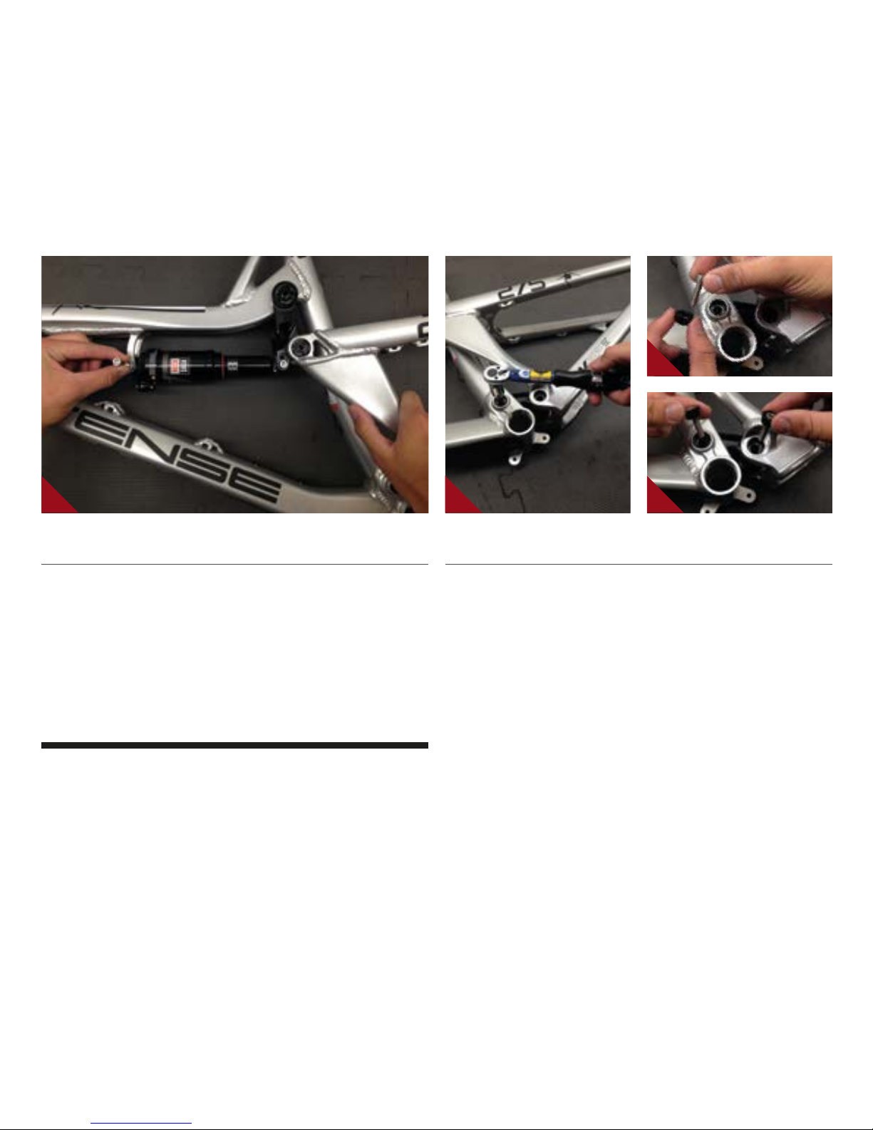
INSTALLING REAR SHOCK //
AUsing rear shock, match forward end to forward shock mount and install M6x40mm
bolt (#410002) through drive side of frame (IMAGE #12). Do not tighten.
BMatch rear end of shock to desired travel setting on upper linkage and install
M6x40mm bolt (#410002) through non-drive side of linkage.
CTighten both M6x40mm (#410002) shock bolts in small increments until you reach
approximately 60 in/lb.
adjustable travel NOTE
the top link of the spider 275 features dual mounting positions. The Upper shock
mounting hole on top link is for LONG travel, the lower hole is for SHORT travel.
for more information see the set up guide on page 14.
12
14
13 15
12 // spider 275 user Manual
INSTALLING ADJUSTER CONES AND FINAL ASSEMBLY (CON'T) //
ATighten M6x22mm bolt (#410009)
with 5mm allen and torque to 125 in/lb
(IMAGE #16).
BTorque shoulder bolts to 175 in/lb
(IMAGE #17). Note: Complete this step
once main pivot bolts, expander cones
and rear shock are all installed.
INSTALLING DERAILLEUR HANGER //
AGrease outer edges of derailleur hanger
(#130790) and add loctite #243 to
threads of hanger bolt (#130792).
BInsert hanger (#130790) into frame
opening on drive side and match with
hanger bolt (#130792), threading
bolt into hanger. Torque to 100 in/lb
(IMAGE #18-20).
16 18
19
17 20

torque
Achieving proper torque is vital to
ensuring the safe performance and
function of the spider 275 frame.
Failure to do so could result in sub-
optimal performance of your frame
as well as premature wear and tear
of individual parts.
additional reference
In addition to this chart, all torque
values are laser etched onto
corresponding hardware for your
reference.
INTENSE CYCLES // 1 3
torque chart
14 Nm / 125 in-lbs
20 Nm / 175 in-lbs
7 Nm / 60 in-lbs
7 Nm / 60 in-lbs
M8 HEX 7 Nm / 60 in-lbs
M6 HEX 14 Nm / 125 in-lbs
M8 HEX 7 Nm / 60 in-lbs
M5 HEX 14 Nm / 125 in-lbs
11 Nm / 100 in-lbs
seatpost
make sure to insert seat post at least
4” into the main frame. Anything less
than this amount could cause damage
to the frame or even failure.
14 // spider 275 user Manual
set up
adjustable travel
upper mount: 130mm
lower mount: 115mm
upper mount
lower mount
4”

INTENSE CYCLES // 1 5
shock setup
rock shox monarch rt3 200x50mm
set up and tune
proper set up and tuning can vary
from shock to shock. Please consult
the rockshox manual included with
your bike for complete information
about set up, tuning and general
maintenance or visit www.sram.com/
rockshox/products
Travel 115 mm 130 mm
Shock Stoke 50 mm
Shock Sag 30% when sitting on the bike
Fork Sag 25-30% when sitting on the bike
SHOCK Rock Shox Monarch RT3 200x50mm
RIDER WEIGHT(LBS/KGS) SPRING (PSI) REBOUND (clicks out) SPRING (PSI) REBOUND (clicks out)
100 lbs/ 45 kgs 92
2 to 3
99
2 to 3
110 lbs/ 50 kgs 98 107
120 lbs/ 54 kgs 104 114
130 lbs/ 59 kgs 110 122
140 lbs/ 63.5 kgs 116 129
150 lbs / 68 kgs 122
3 to 4
137
3 to 4
160 lbs / 72.57 kgs 128 145
170 lbs / 77.11 kgs 133 152
180 lbs / 81.65 kgs 139 160
190 lbs / 86.18 kgs 145 167
200 lbs / 90.72 kgs 151 175
210 lbs / 95.25 kgs 157 182
220 lbs / 99.79 kgs 163 190
230 lbs / 140.33 kgs 169
5 to 6
197
5 to 6
240 lbs / 108.86 kgs 174 205
250 lbs / 113.40 kgs 180 212
260 lbs / 117.93 kgs 186 220
270 lbs / 122.50 kgs 192 227
280 lbs / 127.00 kgs 198 235
290 lbs / 131.54 kgs 204 242
300 lbs / 136.08 kgs 210 250

16 // spider 275 user Manual
shock setup
x-fusion 02 rl 200x50mm
set up and tune
proper set up and tuning can vary from
shock to shock. Please consult the
X-Fusion manual included with your
bike for complete information about
set up, tuning and general maintenance
or visit www.xfusionshox.com
Travel 115 mm 130 mm
Shock Stoke 50 mm
Shock Sag 30% when sitting on the bike
Fork Sag 25-30% when sitting on the bike
SHOCK X-Fusion 02 RL 200x50mm
RIDER WEIGHT(LBS/KGS) SPRING (PSI) REBOUND (clicks out) SPRING (PSI) REBOUND (clicks out)
100 lbs/ 45 kgs 42
2 to 3
54
2 to 3
110 lbs/ 50 kgs 50 63
120 lbs/ 54 kgs 58 71
130 lbs/ 59 kgs 66 80
140 lbs/ 63.5 kgs 74 89
150 lbs / 68 kgs 82
4 to 5
97
4 to 5
160 lbs / 72.57 kgs 90 106
170 lbs / 77.11 kgs 98 114
180 lbs / 81.65 kgs 106 123
190 lbs / 86.18 kgs 113 131
200 lbs / 90.72 kgs 121 140
210 lbs / 95.25 kgs 129 148
220 lbs / 99.79 kgs 137 157
230 lbs / 140.33 kgs 145
6 to 7
165
6 to 7
240 lbs / 108.86 kgs 153 174
250 lbs / 113.40 kgs 161 182
260 lbs / 117.93 kgs 169 191
270 lbs / 122.50 kgs 177 199
280 lbs / 127.00 kgs 184 208
290 lbs / 131.54 kgs 192 217
300 lbs / 136.08 kgs 200 225

INTENSE CYCLES // 1 7
Travel 115 mm 130 mm
Shock Stoke 50 mm
Shock Sag 30% when sitting on the bike
Fork Sag 25-30% when sitting on the bike
SHOCK X-Fusion 02 RL 200x50mm
RIDER WEIGHT(LBS/KGS) SPRING (PSI) REBOUND (clicks out) SPRING (PSI) REBOUND (clicks out)
100 lbs/ 45 kgs 42
2 to 3
54
2 to 3
110 lbs/ 50 kgs 50 63
120 lbs/ 54 kgs 58 71
130 lbs/ 59 kgs 66 80
140 lbs/ 63.5 kgs 74 89
150 lbs / 68 kgs 82
4 to 5
97
4 to 5
160 lbs / 72.57 kgs 90 106
170 lbs / 77.11 kgs 98 114
180 lbs / 81.65 kgs 106 123
190 lbs / 86.18 kgs 113 131
200 lbs / 90.72 kgs 121 140
210 lbs / 95.25 kgs 129 148
220 lbs / 99.79 kgs 137 157
230 lbs / 140.33 kgs 145
6 to 7
165
6 to 7
240 lbs / 108.86 kgs 153 174
250 lbs / 113.40 kgs 161 182
260 lbs / 117.93 kgs 169 191
270 lbs / 122.50 kgs 177 199
280 lbs / 127.00 kgs 184 208
290 lbs / 131.54 kgs 192 217
300 lbs / 136.08 kgs 200 225
18 // spider 275 user Manual
maintenance
GENERAL SERVICE AND CARE //
You have purchased a high performance bicycle which requires a certain level of service
and maintenance to sustain the level of performance your frame was designed around.
Proper care will ensure the bike is safe to ride at all levels. It is important to follow
the maintenance schedule and inspect your bicycle before each ride. These will not
only help to limit or avoid costly repairs but will also help to avoid injury due to service
neglect and component failure.
INTENSE CYCLES // 1 9
maintenance Schedule*
Action Every Ride 500 Miles or
1 Month
2000 Miles or 6
Months
4000 Miles or
1 Year
Tires Check air pressure, inspect tread and sidewalls for tears and punctures X
Chain Brush off and lubricate X
Brakes Squeeze brakes and confirm function X
General Clean complete bike of mud and debris X
Headset Check adjustment X
Box Link Add grease thru zerk fittings X
Frame Pivots Check torques X
Spokes Inspect for damage, check tension X
Shock and Fork Check air pressure, inspect for leaks X
Deraileur Cables Inspect and lube X
Seatpost Clean and regrease interface with frame X
Frame Pivots Remove pivot bolts, check bearings for pitting and wear X
Headset Disassemble stem, headset and fork. Check bearings for pitting and wear X
Hubs Pull wheels off, check hub bearings for pitting and wear X
Bottom Bracket Remove crank arms and check BB bearings for pitting and wear X
Brakes Replace brake pads X
Chain Inspect for damage and check for stretching X
General Complete Tune-Up X
Shock and Fork Overhaul See MFG Recommendations
*THE ABOVE MAINTENANCE SCHEDULE IS ONLY A GUIDELINE. refer to COMPONENT MANUFACTURER FOR SPECIFIC INSTRUCTION ON MAINTAINING THEIR PARTS.

phone: (951)-296-9596
Customer Service: cs@intensecycles.com
General Info: info@intensecycles.com
Media, Marketing, Sponsorship: marketing@intensecycles.com
Intense Cycles USA 42380 rio nedo Temecula, Ca. 92590
www.INTENSeCYCLES.com
330012
Table of contents
Other INTENSEcycles Bicycle manuals

INTENSEcycles
INTENSEcycles M16 Carbon User manual

INTENSEcycles
INTENSEcycles TAZER User manual

INTENSEcycles
INTENSEcycles PRIMER 29 User manual

INTENSEcycles
INTENSEcycles PRIMER 29 User manual

INTENSEcycles
INTENSEcycles 951 EVO User manual

INTENSEcycles
INTENSEcycles Recluse User manual

INTENSEcycles
INTENSEcycles 951 Series User manual

INTENSEcycles
INTENSEcycles ACV User manual

INTENSEcycles
INTENSEcycles ACV User manual

INTENSEcycles
INTENSEcycles Sniper Trail User manual


