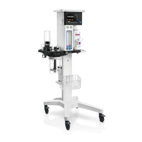
BeneVision N17 User manual

BeneVision N17/BeneVision M17
BeneVision N15/BeneVision M15
BeneVision N12/BeneVision M12/
BeneVision N12C
Patient Monitor
Service Manual


I
Intellectual Property Statement
SHENZHEN MINDRAY BIO-MEDICAL ELECTRONICS CO., LTD. (hereinafter called Mindray) owns the
intellectual property rights to this product and this manual. This manual may refer to information
protected by copyrights or patents and does not convey any license under the patent rights of Mindray,
nor the rights of others. Mindray does not assume any liability arising out of any infringements of patents
or other rights of third parties.
, , and are the registered trademarks or trademarks owned by
Mindray in China and other countries.
Revision History
This manual has a revision number. This revision number changes whenever the manual is updated due to
software or technical specification change. Contents of this manual are subject to change without prior
notice.
Version number: 7.0
Release time: 2022-04
© 2016 -2021 Shenzhen Mindray Bio-Medical Electronics Co., Ltd. All rights reserved.

II
Preface
Manual Purpose
This manual provides detailed information about the assembling, dissembling, testing and
troubleshooting of the equipment to support effective troubleshooting and repair. It is not intended to be
a comprehensive, in-depth explanation of the product architecture or technical implementation.
Observance of the manual is a prerequisite for proper equipment maintenance and prevents equipment
damage and personnel injury.
Intended Audience
This manual is for biomedical engineers, authorized technicians or service representatives responsible for
troubleshooting, repairing and maintaining the monitors
Passwords
A password may be required to access different modes. The passwords are listed below:
User maintenance: 888888
Manage Configuration: 315666
Factory maintenance: 332888
Demo mode: 2088

1
Contents
1 Safety ............................................................................................................................................................. 1-1
1.1 Safety Information.................................................................................................................................................................1-1
1.1.1 Dangers .......................................................................................................................................................................1-1
1.1.2 Warnings .....................................................................................................................................................................1-1
1.1.3 Cautions ......................................................................................................................................................................1-2
1.1.4 Notes ............................................................................................................................................................................1-2
1.2 Equipment Symbols .............................................................................................................................................................1-2
2 Operation Theory .......................................................................................................................................... 2-1
2.1 Overview...................................................................................................................................................................................2-1
2.2 Product System Architecture.............................................................................................................................................2-1
2.2.1 Main Control Board.................................................................................................................................................2-2
2.2.2 Internal Module Rack COM Board .....................................................................................................................2-3
2.2.3 Power Architecture .................................................................................................................................................2-3
2.2.4 Independent Display Board (for the N17/M17 Only)..................................................................................2-4
2.2.5 iView Module (for the N17/M17 Only) .............................................................................................................2-4
2.2.6 Alarm LAMP Board ..................................................................................................................................................2-4
2.2.7 Power Switch Board................................................................................................................................................2-4
2.3 Data Logic Flow......................................................................................................................................................................2-4
3 WLAN Installation ......................................................................................................................................... 3-1
3.1 Introduction.............................................................................................................................................................................3-1
3.2 Network Deployment Process ..........................................................................................................................................3-1
3.2.1 List of outputs...........................................................................................................................................................3-2
3.3 Network Requirements .......................................................................................................................................................3-3
3.4 Network Verification.............................................................................................................................................................3-4
3.4.1 Tools and Resources................................................................................................................................................3-4
3.4.2 Wi-Fi Signal Calibration..........................................................................................................................................3-4
3.4.3 Network Verification Process...............................................................................................................................3-5
3.5 Network Coverage Assessment with Patient Monitors ...........................................................................................3-7
3.6 Recommended Devices for WLAN ..................................................................................................................................3-8
3.7 Setting Wireless Parameters for Patient Monitors .....................................................................................................3-8
3.8 Troubleshooting.................................................................................................................................................................. 3-10
4 Testing and Maintenance ............................................................................................................................. 4-1
4.1 Introduction.............................................................................................................................................................................4-1
4.1.1 Test Equipment.........................................................................................................................................................4-1
4.1.2 Test Report .................................................................................................................................................................4-1
4.1.3 Preventative Maintenance ...................................................................................................................................4-1
4.1.4 Recommended Frequency...................................................................................................................................4-1
4.2 Preventative Maintenance Procedures..........................................................................................................................4-3

2
4.2.1 Visual Inspection......................................................................................................................................................4-3
4.2.2 NIBP Tests....................................................................................................................................................................4-3
4.2.3 Sidestream and Microstream CO2Tests ...........................................................................................................4-6
4.2.4 AG Tests .......................................................................................................................................................................4-9
4.3 Power On Test ...................................................................................................................................................................... 4-11
4.4 Module Performance Tests.............................................................................................................................................. 4-11
4.4.1 ECG Tests.................................................................................................................................................................. 4-11
4.4.2 Resp Performance Test........................................................................................................................................ 4-12
4.4.3 SpO2Test .................................................................................................................................................................. 4-12
4.4.4 NIBP Tests................................................................................................................................................................. 4-13
4.4.5 Temp Test................................................................................................................................................................. 4-13
4.4.6 IBP Tests.................................................................................................................................................................... 4-13
4.4.7 C.O. Test .................................................................................................................................................................... 4-14
4.4.8 Mainstream CO2Tests.......................................................................................................................................... 4-15
4.4.9 Sidestream and Microstream CO2Tests ........................................................................................................ 4-16
4.4.10 AG Tests .................................................................................................................................................................. 4-16
4.4.11 EEG Test.................................................................................................................................................................. 4-16
4.4.12 BIS Test ................................................................................................................................................................... 4-18
4.4.13 RM Test ................................................................................................................................................................... 4-19
4.4.14 CCO/SvO2 Tests .................................................................................................................................................... 4-20
4.4.15 PiCCO Test ............................................................................................................................................................. 4-21
4.4.16 NMT Tests .............................................................................................................................................................. 4-23
4.4.17 ANI Test .................................................................................................................................................................. 4-24
4.5 Nurse Call Relay Performance Test ............................................................................................................................... 4-26
4.6 Analog Output Performance Test ................................................................................................................................. 4-27
4.7 Electrical Safety Tests......................................................................................................................................................... 4-27
4.8 Recorder Check ................................................................................................................................................................... 4-28
4.9 Network Print Test .............................................................................................................................................................. 4-28
4.9.1 Device Connection and Setup ......................................................................................................................... 4-28
4.10 Device Integration Check.............................................................................................................................................. 4-28
4.11 Battery Check..................................................................................................................................................................... 4-28
4.12 Mounting Check ............................................................................................................................................................... 4-29
4.12.1 Safety check ......................................................................................................................................................... 4-29
4.12.2 Overall Test and Check of Installed System .............................................................................................. 4-29
4.13 Factory Maintenance ...................................................................................................................................................... 4-29
4.13.1 Accessing Factory Maintenance Menu....................................................................................................... 4-29
4.13.2 Monitor Information ......................................................................................................................................... 4-30
4.13.3 Production Test ................................................................................................................................................... 4-30
4.13.4 Setup....................................................................................................................................................................... 4-31
4.13.5 Debug..................................................................................................................................................................... 4-31
4.13.6 Power Info............................................................................................................................................................. 4-31
4.13.7 ClinicalData .......................................................................................................................................................... 4-32
4.13.8 Transferring Clinical Data ................................................................................................................................ 4-32
4.13.9 Software Version................................................................................................................................................. 4-32

3
4.13.10 Monitor Information....................................................................................................................................... 4-32
5 Troubleshooting............................................................................................................................................ 5-1
5.1 Introduction.............................................................................................................................................................................5-1
5.2 Part Replacement ..................................................................................................................................................................5-1
5.3 Check before Powering on the Monitor........................................................................................................................5-1
5.4 Software Version Check.......................................................................................................................................................5-1
5.5 Technical Alarm Check.........................................................................................................................................................5-2
5.6 Troubleshooting Guide........................................................................................................................................................5-4
5.6.1 Power On/Off Failures ............................................................................................................................................5-4
5.6.2 Display Failures.........................................................................................................................................................5-4
5.6.3 Module Rack Failures..............................................................................................................................................5-5
5.6.4 Alarm Failures............................................................................................................................................................5-6
5.6.5 Recorder Failures......................................................................................................................................................5-7
5.6.6 Output Interface Failures......................................................................................................................................5-7
5.6.7 Power Supply Failures............................................................................................................................................5-8
5.6.8 Network Related Problems ..................................................................................................................................5-8
5.6.9 Software Upgrade Problems ............................................................................................................................ 5-10
5.6.10 Device Integration Failures............................................................................................................................. 5-10
6 Upgrade ......................................................................................................................................................... 6-1
6.1 Overview...................................................................................................................................................................................6-1
6.2 Upgrade of Parameter Function Modules ....................................................................................................................6-1
6.3 Upgrade of Functional Assemblies .................................................................................................................................6-3
6.3.1 Upgrading SMR ........................................................................................................................................................6-4
6.3.2 Upgrading Wireless Network Functions..........................................................................................................6-4
6.3.3 Upgrading Recorder ...............................................................................................................................................6-4
6.3.4 Upgrading iView System.......................................................................................................................................6-5
6.3.5 Upgrading Independent Display Function ....................................................................................................6-5
6.4 Upgrading Software .............................................................................................................................................................6-6
6.4.1 Description of Network Upgrade Tool .............................................................................................................6-6
6.4.2 Guide to Software Upgrade Operations..........................................................................................................6-9
6.4.3 Guide to Upgrade through a USB Disk ......................................................................................................... 6-10
6.5 Upgrading CAA license function .................................................................................................................................. 6-13
7 Repair and Disassembly ............................................................................................................................... 7-1
7.1 Tools............................................................................................................................................................................................7-1
7.2 Preparations for Disassembly............................................................................................................................................7-1
7.3 Whole Unit Disassembly .....................................................................................................................................................7-2
7.3.1 Basic Disassembly....................................................................................................................................................7-2
7.3.2 Disconnecting the Base.........................................................................................................................................7-3
7.3.3 Separating the Front and Rear Half of the Monitor.....................................................................................7-4
7.4 Further Disassembly of the Front Case Assembly......................................................................................................7-7
7.4.1 Removing the PowerSwitch Board....................................................................................................................7-7

4
7.4.2 Removing the Alarm Lamp and Light Sensor Board ..................................................................................7-7
7.4.3 Removing the Screen Assembly Connection Line ......................................................................................7-8
7.5 Further Disassembly of the Rear Case Assembly .......................................................................................................7-9
7.5.1 Removing the Recorder.........................................................................................................................................7-9
7.5.2 Further Disassembly of the Recorder...............................................................................................................7-9
7.5.3 Removing the MPAN Board .............................................................................................................................. 7-11
7.5.4 Removing the Wi-Fi Module ............................................................................................................................. 7-11
7.5.5 Removing the Internal Module Rack Assembly......................................................................................... 7-12
7.5.6 Removing the Main Support Assembly........................................................................................................ 7-16
7.5.7 Removing the iView Board Assembly (N17 Series)................................................................................... 7-19
7.5.8 Removing the Independent Display Board Assembly (N17/M17 Series)......................................... 7-21
7.5.9 Removing the Handle ......................................................................................................................................... 7-22
7.6 Further Disassembly of the Base Assembly .............................................................................................................. 7-22
7.7 Disassembling the Module Rack................................................................................................................................... 7-23
7.8 Disassembling the M51C Module................................................................................................................................. 7-26
8 Parts ............................................................................................................................................................... 8-1
8.1 N17/M17/N15/M15/N12/M12 Whole Unit ...................................................................................................................8-1
8.1.1 Exploded View ..........................................................................................................................................................8-1
8.1.2 Parts List ......................................................................................................................................................................8-1
8.2 N12/M12 Front Housing view ...........................................................................................................................................8-2
8.2.1 Exploded View ..........................................................................................................................................................8-2
8.2.2 Parts List ......................................................................................................................................................................8-2
8.3 N12/M12 Rear Housing View.............................................................................................................................................8-3
8.3.1 Exploded View ..........................................................................................................................................................8-3
8.3.2 Parts List ......................................................................................................................................................................8-3
8.4 N12/M12 Internal Module Rack Assembly ...................................................................................................................8-4
8.4.1 Exploded View ..........................................................................................................................................................8-4
8.4.2 Parts List ......................................................................................................................................................................8-4
8.5 N12/M12 Main Bracket Assembly....................................................................................................................................8-5
8.5.1 Exploded View ..........................................................................................................................................................8-5
8.5.2 Parts List ......................................................................................................................................................................8-5
8.6 N12/M12 Bottom Housing .................................................................................................................................................8-6
8.6.1 Exploded View ..........................................................................................................................................................8-6
8.6.2 Parts List ......................................................................................................................................................................8-6
8.7 N15/M15 Front Housing View...........................................................................................................................................8-7
8.7.1 Exploded View ..........................................................................................................................................................8-7
8.7.2 Parts List ......................................................................................................................................................................8-7
8.8 N15/M15 Rear Housing View.............................................................................................................................................8-8
8.8.1 Exploded View ..........................................................................................................................................................8-8
8.8.2 Parts List ......................................................................................................................................................................8-8
8.9 N15/M15 Internal Module Rack Assembly ...................................................................................................................8-9
8.9.1 Exploded View ..........................................................................................................................................................8-9
8.9.2 Parts List ......................................................................................................................................................................8-9

5
8.10 N15/M15 Main Bracket Assembly .............................................................................................................................. 8-10
8.10.1 Exploded View..................................................................................................................................................... 8-10
8.10.2 Parts List................................................................................................................................................................. 8-10
8.11 N15/M15 Bottom Housing............................................................................................................................................ 8-11
8.11.1 Exploded View..................................................................................................................................................... 8-11
8.11.2 Parts List................................................................................................................................................................. 8-11
8.12 N17/M17 Front Housing View...................................................................................................................................... 8-12
8.12.1 Exploded View..................................................................................................................................................... 8-12
8.12.2 Parts List................................................................................................................................................................. 8-12
8.13 N17/M17 Rear Housing View ....................................................................................................................................... 8-13
8.13.1 Exploded View..................................................................................................................................................... 8-13
8.13.2 Parts List................................................................................................................................................................. 8-13
8.14 N17/M17 Main Bracket Assembly .............................................................................................................................. 8-14
8.14.1 Exploded View..................................................................................................................................................... 8-14
8.14.2 Parts List................................................................................................................................................................. 8-14
8.15 N17/M17 Independent Display Assembly .............................................................................................................. 8-15
8.15.1 Exploded View..................................................................................................................................................... 8-15
8.15.2 Parts List................................................................................................................................................................. 8-15
8.16 N17/M17 Bottom Housing............................................................................................................................................ 8-16
8.16.1 Exploded View..................................................................................................................................................... 8-16
8.16.2 Parts List................................................................................................................................................................. 8-16
8.17 MPM module (M51A)...................................................................................................................................................... 8-17
8.17.1 Exploded View..................................................................................................................................................... 8-17
8.17.2 Parts List................................................................................................................................................................. 8-17
8.18 M51C Module (Platinum) .............................................................................................................................................. 8-18
8.18.1 Exploded View..................................................................................................................................................... 8-18
8.18.2 Parts List................................................................................................................................................................. 8-18
8.19 Others................................................................................................................................................................................... 8-19

6
FOR YOUR NOTES

1-1
1Safety
1.1 Safety Information
DANGER
Indicates an imminent hazard that, if not avoided, will result in death or serious injury.
WARNING
Indicates a potential hazard or unsafe practice that, if not avoided, could result in death or serious injury.
CAUTION
Indicates a potential hazard or unsafe practice that, if not avoided, could result in minor personal injury
or product/property damage.
NOTE
Provides application tips or other useful information to ensure that you get the most from your product.
1.1.1 Dangers
There are no dangers that refer to the product in general. Specific “Danger” statements may be given in the respective
sections of this manual.
1.1.2 Warnings
WARNING
All installation operations, expansions, changes, modifications and repairs of this product are conducted
by Mindray authorized personnel.
There is high voltage inside the equipment. Never disassemble the equipment before it is disconnected
from the AC power source.
When you disassemble/reassemble a parameter module, a patient leakage current test must be
performed before it is used again for monitoring.

1-2
The equipment must be connected to a properly installed power outlet with protective earth contacts
only. If the installation does not provide for a protective earth conductor, disconnect it from the power
line and operate it on battery power, if possible.
Dispose of the package material, observing the applicable waste control regulations and keeping it out of
children’s reach.
1.1.3 Cautions
CAUTION
Make sure that no electromagnetic radiation interferes with the performance of the equipment when
preparing to carry out performance tests. Mobile phone, X-ray equipment or MRI devices are a possible
source of interference as they may emit higher levels of electromagnetic radiation.
Before connecting the equipment to the power line, check that the voltage and frequency ratings of the
power line are the same as those indicated on the equipment’s label or in this manual.
Protect the equipment from damage caused by drop, impact, strong vibration or other mechanical force
during servicing.
1.1.4 Notes
NOTE
Refer to Operation Manual for detailed operation and other information.
1.2 Equipment Symbols
See the N series Operator’s Manual for information about the symbols used on this product and its packaging.

2-1
2Operation Theory
2.1 Overview
As a bedside workstation for multi-parameter monitoring, the N series and M series can provide the complete patient
management, abundant physiological parameter monitoring and physiological alarm functions, as well the powerful
data review function and the flexible wired and wireless network configuration and application capabilities. The third-
party application can be accessed easily through the iView application, meeting the increasingly common information
requirements of hospitals. The provided series of CAA applications can help doctors to make auxiliary diagnosis for
patients. Meanwhile, the N series and M series provide the hospital management personnel with more excellent monitor
management applications, rendering assistance in fixing the efficiency and quality problems during monitor equipment
management of hospitals.
The N series and M series provide the product models with display screens of different sizes according to the demand of
clinical application. In addition to touch screen operations, the user can use the mouse and keyboard to operate the
monitor. The N series and M series can connect to multiple display screens to function as mirror screens or extension
screens.
The series of products are compatible with the BeneView T series plug-in modules and related accessory products. They
can work together with the TDS to implement the intra-hospital transfer application of patients.
In comparison with the BeneView T series products, the N series and M series boast better human-computer interaction
design and clinical applicability, more complete IT solution capability of hospitals, and more abundant CDS applications.
2.2 Product System Architecture
All the N17/N15/N12/M17/M15/M12 monitors have only one main unit:
The N12/M12 main unit uses the 12.1” TFT WXGA display screen.
The N15/M15 main unit uses the 15.6” TFT FHD display screen.
The N17/M17 main unit uses the 18.5”TFT FHD display screen.
All of them use the touch screen as an input device and can extend the mouse, keyboard and remote control.
An internal module rack is integrated, with 4 slots (N12) or 6 slots (N15/N17).
The MPAN and WiFi modules are optional.
The built-in recorder is optional.
The N15/M15/N17/M17 can connect to the external module rack and TDS; the N12/M2 can connect to the
TDS.

2-2
Main control board
LCD
iView assembly
(N17 Optional)
DVI RJ45 2*USB 2*USB
Power switch
board
Alarm lamp
board
MPAN module
(Optional)
TP control
board
AC/DC
module
Battery interface
board
(N15/N17)
Recorder
(Optional)
Speaker
Battery
Front
shell
Back
shell
AC/DC
interface
2*USB 2*USB DVI RJ45
WiFi module
(Optional)
Independent display board
(N17 Optional)
DVI
Internal module com board(4slots/6slots)
4/6*Module
communication
interface
Nurse call
interface
SMR
interface
Bottom
shell
Battery interface
board
(N12/N12C)
Battery
Figure 2-1 System block diagram of the N17/M17/N15/M115/N12/N12C/M12
2.2.1 Main Control Board
There are the main control CPU, program memory, data memory, system configuration memory, system FPGA, Wi-Fi
module (optional), power management MCU, battery charging circuit, and DC-DC circuit on the main control board. The
internal interface and external interfaces are also provided on the board. The internal interface is an interface between
the recorder, internal module rack COM board, AC-DC, and the battery. The external interfaces refer to the DVI display
interface, USB interface, and Ethernet interface.
Main Processor
DDR3
Program
Memory
Data Memory
E2ROM
USB hub
Touch-
controller SPI
USB
Audio
codec/AMP
Speaker
Touch panel
Power M0
PHY
WiFi
(optional)
Internal Module
Rack communication
board
RTC
Photo
senseor
Power key board
RJ-45
DVI
interface
USB 4*port
MMC
MMC
RMII1PHY
Independent
display
board/iView
MPAN Module
E2ROM(funnct
ion cfg)
Nursecall
interface
Alarm light
controller
SMR
Interface
FPGA
(N15/N17)LCD
Back light
driver
DVI
transfer
SPI
UART
LCDC
I2C
I2C
Main
Control
board
Figure 2-2 Diagram of the main control board

2-3
2.2.2 Internal Module Rack COM Board
Two models of internal module rack COM boards are available. The N12/M12 uses the 4-slot COM board, and the
N15/M15/N17/M17 uses the 6-slot COM board. The internal module rack COM board is used to provide the interface for
communication with the parameter module, the SMR interface and nurse call interface, and the MPAN module interface.
Besides, the data forwarding FPGA and corresponding power circuit are also provided on the internal module rack COM
board.
2.2.3 Power Architecture
AC/DC
module
100~240V AC AC-DC in
Battery
BAT
charger
switch
M0
DC/DC
+12V
DC/DC
LDO
+3.3V_1
VBUS:
9.6~11.1V,
+15V
ON/OFF
ON/OFF
+5V
Power switch
board
+5V/+3.3V +3.3V
Alarm lamp
board
Photo
senseor
Led driver
Recorder
+12V
LCD&TP
+12V
Internal module rock COM
board
iView module
+12V
Independent display
board
+5V
+5V
ON/OFF
+3.3V
DC/DC
DC/DC
+3.3V_2 MPAN module
Figure 2-3 Diagram of power architecture
The AC/DC power module outputs 15V to the main control board, and 3.3V, 5V and 12V can be generated through the
internal DC-DC conversion circuit in the main control board to provide a power supply to other modules or boards in the
main unit. The battery charging circuit is powered by 15V, and the AC power supply and battery power supply can be
switched according to AC on-line detection.
The +12V power supply is provided to the power supply, including the external module rack, and the DC-DC isolation
design is implemented at the module end.
The iVIew assembly uses the power rail Vbus, which is the switching output between the AC-DC output and battery and
aims to avoid abnormal power failure of the iView module and running exception of the Windows OS running on other
modules due to an unexpected power failure of the AC power supply. The battery supports the main unit to stop the
iView module in the normal power-off mode. In the case of battery power supply, the iView module cannot start.

2-4
2.2.4 Independent Display Board (for the N17/M17 Only)
It is used to connect the main unit to a display and extend the main screen display. It adopts the DVI interface. Moreover,
the external display with a touch screen can be supported through the USB interface of the main unit. At present, the
supported display with a touch screen is Elo 1919LM.
2.2.5 iView Module (for the N17/M17 Only)
As an embedded computer module, it provides the following external interfaces: the network interface, DVI interface,
and the USB interface. It can connect to the keyboard, mouse, network cable, and display independently. The
configuration of the iView module is mutually exclusive with that of the independent display module.
2.2.6 Alarm LAMP Board
The LED alarm lamp and light sensor are provided on the board. The light sensor implements the ambient light
detection and is used to adjust brightness of the LCD background light.
2.2.7 Power Switch Board
There are the power switch and three indicators on the power switch board, which are the AC on-line indicator, battery
indicator, and the power-on indicator.
2.3 Data Logic Flow
Data
collection
Data
forwarding
System
application
Display and
user interface
Data
output
Data storage
Figure 2-4 Data flow diagram
The monitoring parameters are collected and analyzed through the module, and then forwarded to the system software
through the internal or external module rack. The system software displays the waveform, numerical value and alarm
information, and the data, alarm information and numerical value are also stored in the internal data memory at the
same time. Meanwhile, they can also be sent to the central station or other monitors through the wired or wireless
network.

3-1
3WLAN Installation
3.1 Introduction
This chapter describes how to install Mindray patient monitors using WLAN.
3.2 Network Deployment Process
If the hospital has built its WLAN, the installation process is illustrated as follows:
Mindray/agent
marketing or sales
personnel
Mindray
headquarters
Mindray/agent
service personnel
A1 Communicate with
the hospital about
intention to order
A5 Install the device
and confirm system
operation
A0 Provide network
requirements
A2 Communicate with the
hospital about network
requirements and ask the
hospital to perform
corresponding setting and
adjustment
Pass or fail
Pass
A4 Sign the contract
A3 Do site survey

3-2
3.2.1 List of outputs
Action Output Requirements Template
A0 Wireless Network requirements
for Mindray patient monitors
Determine requirements for deployment of
the wireless network for Mindray patient
monitors.
Wireless Network Requirement
Table in 3.3 Network
Requirements
A3 Network acceptance report Confirm that the customer network meets
requirements of Mindray patient monitors by
means of questionnaire and measurement.
Wireless Network Acceptance
Table in 3.4.3 Network
Verification Process
A5 Installation confirmation report Confirm the actual operation of the Mindray
patient monitors after installation.
Patient Monitor Installation
Confirmation Table in 3.5 Network
Coverage Assessment with
Patient Monitors
If the hospital plans to build a new WLAN for the Mindray patient monitors, make sure that there is at least one idle Wi-Fi
channel that is not in use. Otherwise, you can’t make co-channel interference meet Mindray patient monitors’
requirement after the new WLAN is built. The installation process is illustrated as follows:
Mindray/agent
marketing or sales
personnel
Mindray
headquarters
Mindray/agent
service personnel
A1 Communicate with
the hospital about
intention to order
A5 Install the device
and confirm system
operation
A0 Provide network
requirements
A4 Install network
A2 Do site survey and
design network
A3 Sign the contract

3-3
Action Output Requirements Template
A0 Wireless Network
requirements for Mindray
patient monitors
Determine requirements for deployment
of the wireless network for Mindray
patient monitors.
Wireless Network Requirement Table in
3.3 Network Requirements
A2 Network design document,
Bill of material
/ /
A5 Installation confirmation
report
Confirm the actual operation of the
Mindray patient monitors after
installation.
Patient Monitor Installation Confirmation
Table in 3.5 Network Coverage
Assessment with Patient Monitors
NOTE
Network design and deployment project needs much more complex process, you need professional IT
engneer’s help to finish the job. This document does not include these contents.
3.3 Network Requirements
The Wireless infrastructure needs to meet the following requirements.
Table 3-1 Wireless Network Requirement Table
No. Item Content of Requirements
Wireless coverage requirements
1 Received signal
strength (RSSI)
≥-65 dBm
RSSI is the value displayed on the patient monitor
2 Co-channel
interference
≤-20dB (co-channel interference AP’s RSSI shall be at least 20 dB lower than the AP that
patient monitor uses.)
3 Ping delay The mean delay of PC or cell phone is smaller than 100ms and The packet lost rate shall be less
than 1%.
Requirements of AP capability
1 AP
capability
1.The anticipated number of devices connecting to one AP must be lower than 50% of the AP
capability. For example, In the coverage of one AP, the typical number of devices connected to
this AP is 16, then the announced number of devices that can connect to AP simultaneously
must be more than 32.
2.The AP Can create several SSIDs.
2 Device
density
The maximum number of devices connected to one AP simultaneously is 16 (including patient
monitors and other devices).
WLAN features
1 AP channel
width
Set the channel width to 20MHz, don’t use HT40 or even HT80.
2 802.11
protocol
WLAN can't use protocols that Mindray patient monitor can’t support, e.g 802.11ac
3 Security mode WLAN can't use Security mode that Mindray patient monitor can’t support.
Using WPA2-Enterprise or WPA2-PSK is recommended. Use a long password and change it

3-4
No. Item Content of Requirements
frequently. If the hospital network supports WPA2-Enterprise, using WPA2-Enterprise can
achieve higher security.
4 Dedicated VLAN The patient monitors need to work on a dedicated VLAN.
Using VLAN can minimize Broadcast or multicast data which can affect patient monitors’
stability.
Important settings
1 DHCP The DHCP server reserves a sufficient number of IP addresses to ensure that the patient
monitors can obtain an IP address.
2 IGMP snooping If patient monitors use multicast, enable IGMP snooping
3 Multicas If patient monitors use multicast, the multicast function of network should be enabled.
4 Beacon & DTIM AP DTIM = 1, Beacon = 100ms
5 Service port Refer to Mindray Patient Monitoring Network Whitepaper; patient monitors need some
certain TCP/UDP ports to be opened
3.4 Network Verification
3.4.1 Tools and Resources
Laptop computer, where Windows 7 or later version is installed and wireless network card is equipped. We
recommended laptop configured with Intel Centrino Wireless-N adapter. If your laptop is configured with some
other wireless adapter, please make sure the adapter has a high degree of accuracy.
Wireless network survey tool, we suggest to use professional survey tool such as tamograph, Wirelessmon or other
professional network survey tool.
Professional network engineer.
NOTE
The personnel who implement the Wi-Fi network survey should be well trained about Wi-Fi. If
professional network engineers are not available, please ask some third party for help.
3.4.2 Wi-Fi Signal Calibration
Before a wireless network survey tool (running on laptop computer) is used to test network coverage, follow this
procedure to calibrate the RSSI of wireless network survey tool with a patient monitor
1. Keep the patient monitor and wireless network survey tool close. The distance between them is not greater than
30cm and the distance from human body is above 50 cm.
2. Move the patient monitor and Wireless network survey tool at the same time (keep the previous distance).
3. When the patient monitor reads the following RSSI values: -50 dBm, -60 dBm, -70 dBm and -80 dBm, record the RSSI
values read by Wireless network survey tool.
4. Calibrate the RSSI of Wireless network survey tool to patient monitor when do site survey (the RSSI of Patient
monitor is the benchmark to wireless coverage).
This manual suits for next models
6
Table of contents
Other BeneVision Medical Equipment manuals
Popular Medical Equipment manuals by other brands
Otto Bock
Otto Bock 50R301N Dyneva light Instructions for use

Otto Bock
Otto Bock Omo Immobil Sling Instructions for use

PremiumLift
PremiumLift AirCare Max-Pro ACMaxPP user manual

Stryker Medical
Stryker Medical Renaissance Series Maintenance manual

Tremitas
Tremitas Tremipen Home Instructions for use

PROVOX
PROVOX Vega manual
