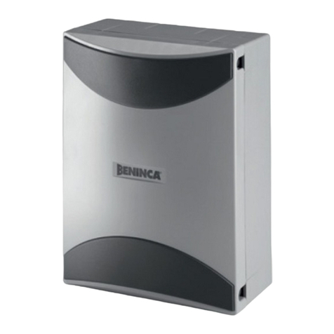
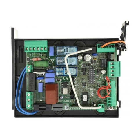
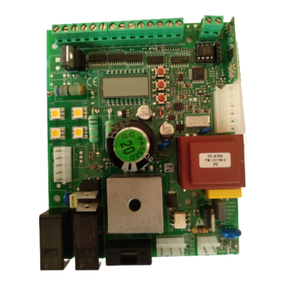
Beninca RI.624 User manual

L8542711
Rev. 12/06/05
Libro istruzioni
Operating instructions
Betriebsanleitung
Livret d’instructions
Manual de instrucciones
Książeczka z instrukcjami
UNIONE NAZIONALE COSTRUTTORI
AUTOMATISMI PER CANCELLI, PORTE,
SERRANDE ED AFFINI
RI.624
CENTRALE DI COMANDO
CONTROL UNIT
STEUEREINHEIT
CENTRALE DE COMMANDE
CENTRAL DE MANDO
CENTRALKA STEROWANIA
www.gałecki.pl

2
3
Dichiarazione CE di conformità Déclaration CE de conformité
EC declaration of conrmity Declaracion CE de conformidad
EG-Konformitatserklarung Deklaracja UE o zgodności
Con la presente dichiariamo che il nostro prodotto
We hereby declare that our product
Hiermit erklaren wir, dass unser Produkt
Nous déclarons par la présente que notre produit
Por la presente declaramos que nuestro producto
Niniejszym oświadczamy że nasz produkt
RI.624
è conforme alle seguenti disposizioni pertinenti:
complies with the following relevant provisions:
folgenden einschlagigen Bestimmungen entspricht:
correspond aux dispositions pertinentes suivantes:
satisface las disposiciones pertinentes siguientes:
zgodny jest z poniżej wyszczególnionymi rozporządzeniami:
Direttiva sulla compatibilità elettromagnetica
(89/336/CCE, 93/68/CEE)
EMC guidelines (89/336/EEC, 93/68/EEC)
EMV-Richtlinie (89/336/EWG, 93/68/EWG)
Directive EMV (89/336/CCE, 93/68/CEE)
(Compatibilité électromagnétique)
Reglamento de compatibilidad electromagnética
(89/336/MCE, 93/68/MCE)
Wytyczna odnośnie zdolności współdziałania elektromagne-
tycznego (89/336/EWG, 93/68/EWG)
Benincà Luigi, Responsabile legale.
Sandrigo, 01/06/2006.
Direttiva sulla bassa tensione (73/23/CEE, 93/68/CEE)
Low voltage guidelines (73/23/EEC, 93/68/EEC)
Tiefe Spannung Richtlinie (73/23/EWG, 93/68/EWG)
Directive bas voltage (73/23/CEE, 93/68/CEE)
Reglamento de bajo Voltaje (73/23/MCE, 93/68/MCE)
Wytyczna odnośnie niskiego napięcia (73/23/EWG,
93/68/EWG)
Automatismi Benincà SpA
Via Capitello, 45
36066 Sandrigo (VI)
ITALIA
www.gałecki.pl

2
3
SW1
19 20 21
30
31
32
33
34
35
24
25
26
27
28
29
+5V
CH
PROG
DISPLAY
BYPASS
SELECT
AP
+24V
24Vdc
LAMP
24Vdc
SCA 24V
3W max
F3
STP J1J2
FCC
FCA
FTC
F2
F1
ASC
ASA
ASA
2 CH
COM FC
COM
COM
CLOSE
N.O.
N.O.
N.O.
N.C.
N.C.
N.C.
N.C.
OPEN
P.P.
STOP
FCC
FCA
FTC
ASC
COM AS
24V 12V LAMP 24V SCA
BATTERY 0V
ASA
2A
1
CH AP PP STP FCC FCA FTC
RADIO
RC1
1
6
8
1A
10A
+
-
PC
+
-
PA
34
125678910 11 12 13 14 15 16 17 18
A
NT
SHIELD
ANT
N.O.
24Vac
230Vac
L
N
22
23
M
230Vac
50Hz
+ - + -
ASC
N.B: Non effettuare ponticelli su morsettiera, uti-
lizzare esclusivamente gli appositi Dip-Switch
BYPASS
N.B: Do not make jumpers on the terminal board,
use only the special “BYPASS” Dip-Switches.
NB: Keine Brücken an der Klemmenleiste herstellen,
sondern ausschließlich die speziellen Dip-Switches
“BYPASS” verwenden
N.B.: Ne pas mettre de cavaliers sur le bornier,
utiliser exclusivement les dip-switchs «BYPASS»
prévus à cet effet
N.B: No realizar ningún conector puente en el termi-
nal de bornes, utilizar exclusivamente los relativos
Dip-Switch “BYPASS”
UWAGA: Nie wykonywać mostkowania na listwie
zaciskowej, stosować wyłącznie specjalne do
tego Dip-Switch “BYPASS”
www.gałecki.pl

4
5
Centrale per RI.624
La centrale a microcontrollore “Ri.624” può essere usata per comandare motori a 24Vdc di potenza non superiore a 160W.
Ingressi/Uscite
N° Morsetti Funzione Descrizione
1 Comune finecorsa Morsetto comune per gli ingressi FCA e FCC (vedi “Installazione della centrale”).
2,3 Uscita +V Morsetto comune per tutti gli ingressi.
4 Ingresso CHIUDE Contatto N.O.
5 Ingresso APRE Contatto N.O. (Commutabile a ingresso “Pedonale”).
6 Ingresso P.P. Ingresso Passo-Passo. Collegato in parallelo all’uscita del radiocomando. Contatto N.O.
7 Ingresso STOP Contatto N.C.
8 Ingresso FCC Ingresso finecorsa di chiusura. Contatto N.C.
9 Ingresso FCA Ingresso finecorsa di apertura. Contatto N.C.
10 Ingresso FTC Da collegare al contatto di uscita della fotocellula. Contatto N.C.
11,12 Ingresso ASC Ingresso per costa o dispositivo di sicurezza il cui intervento provoca l’inversione di marcia per 1 secondo
se il motore è in fase di chiusura*.
12,13 Ingresso ASA Ingresso per costa o dispositivo di sicurezza il cui intervento provoca l’inversione di marcia per 1 secondo
se il motore è in fase di apertura*.
14,15 Uscita 24Vdc Uscita alimentazione ausiliaria 24Vdc. “-“ = mors. 14, “+” = mors. 15
16,17,18 Ingresso Batteria Collegamento per batteria tampone (2x12V): mors. 16= 24V, mors. 17= 12V , mors. 18= 0V e cavo giallo-
verde di Terra dell’impianto elettrico.
19,20 Uscita LAMP Al lampeggiante. Lampada 24V - 10W max.
20,21 Uscita SCA Alla “Spia Cancello Aperto”. Lampada 24V - 3W max.
22,23 Uscita Motore Al motore 24Vdc.
24,25 Ingresso secondario Al secondario del trasformatore 24Vac.
26,27 Ingresso primario Al primario del trasformatore 230Vac.
28,29 Ingresso 230Vac Alimentazione centrale 220Vac - 50Hz, Neutro= mors. 28, Fase= mors. 29.
32,33 Uscita 2° canale Contatto N.O. comandato dal secondo canale del radiocomando.
34,35 Ingresso Antenna Collegamento antenna per scheda ricevente del radiocomando. Schermo= mors. 34
RIC1 Connettore scheda ricevente del radiocomando
* L’ingresso della costa è un ingresso a resistenza calibrata.
Se si usa una costa resistiva Chiudere il rispettivo Ponticello: J1 per ASC e J2 per ASA.
Se si usa una costa meccanica Aprire il rispettivo Ponticello: J1 per ASC e J2 per ASA.
Se non si desidera montare una costa, Aprire il relativo Ponticello e posizionare su ON il DSW di cortocircuito. 5-ASC, 6-ASA.
N.B.: Per la costa ci sono due ingressi dedicati, NON COLLEGARE MAI LA COSTA AL MORSETTO COMUNE
Led
+5V Alimentazione dei circuiti di controllo. Se il led è spento, controllare il fusibile F1 (2A).
+24V Alimentazione del motore. Se il led è spento, controllare il fusibile F3 (10A).
PROG. Lampeggiante durante il funzionamento normale della centrale.
CH Segnala che il motore è in fase di chiusura.
AP Segnala che il motore è in fase di apertura.
Trimmer
PA Regola la soglia del limitatore di coppia del motore durante la fase di apertura (soglia massima= senso orario).
PC Regola la soglia del limitatore di coppia del motore durante la fase di chiusura (soglia massima= senso orario).
Installazione della centrale
1 Dopo aver valutato le caratteristiche e i rischi dell’impianto, escludere tutti gli ingressi normalmente chiusi che non si desidera utilizzare: Stop (7),
FCC (8), FCA (9), FTC (10), ASC (11), ASA (13), utilizzando i 6 dip-switch vicini alla morsettiera estraibile.
Le corrispondenze sono: 1= Stop, 2= FCC , 3= FCA, 4= FTC, 5= ASC, 6= ASA.
N.B.: Tra i morsetti Com.Fc (1) e Com. (2) è collegato un microinterrutore che fa eseguire la taratura della corsa quando viene azionato lo sblocco
manuale del motore, se si montano i finecorsa il Comune dei finecorsa va collegato al morsetto Com.Fc (1) assieme ad uno dei cavi del microinter-
rutore di sblocco (l’altro cavo del microinterrutore di sblocco resta collegato al morsetto Com. (2) assieme ad eventuali altri comuni dei pulsanti.
Se la costa sensibile è montata sul bordo di chiusura o di apertura, le connessioni dovrebbero essere portate agli ingressi “ASC” e “ASA” rispettivamente.
Collegare il morsetto “0V” (18) al cavo giallo-verde di terra dell’impianto elettrico.
2 Collegare gli ingressi di comando: P.P. (6) ,Apre (5), Chiude (4).
3 Collegare l’alimentazione 24Vdc (14,15) ad eventuali dispositivi collegati alla centrale (fotocellule, ricevitori,…) rispettando la corretta polarità. Col-
legare il lampeggiante e l’eventuale “spia cancello aperto” (lampade 24V-3W).
4 Dopo aver ricontrollato i collegamenti, alimentare la centrale ai morsetti di ingresso 230Vac (28,29). All’accensione dovrebbero essere accesi i led
+5V, +24V, STOP, FTC. Almeno uno dei led FCA o FCC deve essere acceso. Il led PROG deve lampeggiare.
5 La prima manovra della centrale è eseguita a velocità ridotta per ricavare la corsa del cancello.
• Regolare i trimmer PA e PC a metà.
• Dare un comando di apertura (Apre, P.P., radiocomando).
• La centrale esegue il prelampeggio e quindi inizia la fase di apertura. Il cancello si ferma tutto aperto per blocco meccanico o sul FCA se questo
è montato.
Il lampeggiante non si spegne e dopo 3 secondi inizia automaticamente la chiusura. La taratura termina alla fine della manovra di chiusura, cioè
sul blocco meccanico di chiusura o sul FCC se questo è montato. La procedura non termina se il motore viene fermato da un comando ( PP,
Stop, fotocellula, …). Dopo la taratura della corsa, è necessario eseguire la regolazione dei trimmer PA e PC, che consentono di limitare la potenza
www.gałecki.pl

4
5
massima fornita al motore. Per regolare il trimmer PA, iniziare una manovra di apertura e variare verso il minimo (senso antiorario) il trimmer fino
ad ottenere l’intervento del limitatore con la conseguente breve inversione di marcia. Aumentare quindi gradualmente la soglia fino a ottenere una
regolazione ottimale. Il procedimento per il trimmer PC è analogo e riguarda le manovre di chiusura.
6 Impostare i Dip-Switch e le funzioni programmabili secondo le proprie esigenze (non è necessario spegnere e riaccendere la centrale).
AVVERTENZE
Sblocco manuale
Quando il motore viene sbloccato, il contatto normalmente chiuso collegato tra i morsetti Com. (2) e Com.Fc. (1) si apre.
Quando, dopo aver bloccato il motore, viene dato il primo comando di apertura, la centrale esegue una nuova taratura della corsa.
Batterie tampone
• Se si utilizzano delle batterie tampone (2x12V in serie), per togliere completamente l’alimentazione alla centrale è sufficiente scollegare il morsetto
“0V” (18).
• Il caricabatteria integrato nella centrale necessita di alcuni giorni per fornire una ricarica completa alle batterie.
• Durante il funzionamento a batteria, il motore ha una velocità di marcia leggermente minore rispetto al funzionamento normale, indipendentemente
dal livello di carica delle batterie.
• Corretto collegamento delle batterie:
+24V (16)
+12V (17)
0V (18)
+ -
+ -
Funzioni dip-switch "SELECT"
DSW1 Modo di funzionamento per l’ingresso ”P.P.”
OFF: Sequenza Apre/STOP/Chiude/STOP
ON: Sequenza Apre/Chiude
DSW2 Funzione ”Chiusura Automatica”
OFF: Disabilitata
ON: Abilitata
Per ragioni di sicurezza, la funzione ”Chiusura Automatica” è sempre disabilitata a seguito di un comando agli ingressi di ”STOP”, o se viene
rilevato un ostacolo dal sensore di giri.
DSW3 Funzione ”Condominiale”: l’ingresso ”P.P.” non ferma il motore durante la fase di apertura. Ad apertura completata, l’ingresso ”P.P.” è abilitato
per la chiusura del cancello.
OFF: Disabilitata
ON: Abilitata
DSW4 Funzione ”Prelampeggio”: la luce lampeggiante viene attivata 3 secondi prima dell’inizio di ogni manovra.
OFF: Disabilitata
ON: Abilitata
DSW5 Intervento fotocellula durante la fase di apertura: se il fascio della fotocellula viene interrotto, il motore si ferma. La manovra riprende qualche
secondo dopo che la fotocellula viene disimpegnata.
OFF: Disabilitata
ON: Abilitata
DSW6 Funzione ”Pedonale”: l’ingresso ”Apre” comanda l’apertura parziale.
OFF: Disabilitata
ON: Abilitata
DSW7 Modo operativo della funzione ”Pedonale”.
OFF: L’ingresso ”Apre” comanda solo l’apertura.
ON: L’ingresso ”Apre” ha le stesse funzioni dell’ingresso ”P.P.”
DSW8 Modo operativo della ”Spia cancello aperto”
OFF: Funzionamento normale ON/OFF.
ON: Funzionamento lampeggiante: in fase di apertura la spia lampeggia lentamente, completata l’apertura la spia rimane accesa, in fase di
chiusura la spia lampeggia velocemente.
Funzioni programmabili
Le funzioni per le quali è possibile scegliere tra un intervallo di valori, vengono impostate utilizzando il pulsante di programmazione (PROG.) assieme
ai dip-switch "SELECT".
I valori predefiniti sono indicati con ”(def.)”. Per memorizzare le funzioni programmabili, posizionare i dip-switch come indicato in tabella, quindi pre-
mere il pulsante ”PROG.” per almeno 2 secondi. Il led ”PROG.” si spegne e quindi si accende per 2 secondi circa per indicare la memorizzazione dei
valori. Una volta terminata la programmazione, riportare i dip-switch nelle posizioni normali.
Per semplificare questa operazione, annotare le impostazioni di base nella seguente tabella.
www.gałecki.pl

6
7
Tempo d’attesa per la chiusura automatica.
La chiusura del contatto sull’ingresso di APRE provoca una ricarica del tempo di attesa. L’intervento della FTC provoca il ricarico completo del tempo
di attesa oppure la diminuzione dello stesso ad 1/4 del valore impostato in funzione della programmazione selezionata.
Secondi
5
10
15
20
30
40
50
60 (def.)
80
100
120
140
160
180
200
220
Dsw8
Off
On
Off
On
Off
On
Off
On
Off
On
Off
On
Off
On
Off
On
Dsw7
Off
Off
On
On
Off
Off
On
On
Off
Off
On
On
Off
Off
On
On
Dsw6
Off
Off
Off
Off
On
On
On
On
Off
Off
Off
Off
On
On
On
On
Dsw5
Off
Off
Off
Off
Off
Off
Off
Off
On
On
On
On
On
On
On
On
Dsw4
ON
Dsw3
ON
Dsw2
OFF
Dsw1
OFF
Tempo di lavoro.
Secondi
5
10
15
20
30
40
50
60 (def.)
80
100
120
140
160
180
200
220
Dsw8
Off
On
Off
On
Off
On
Off
On
Off
On
Off
On
Off
On
Off
On
Dsw7
Off
Off
On
On
Off
Off
On
On
Off
Off
On
On
Off
Off
On
On
Dsw6
Off
Off
Off
Off
On
On
On
On
Off
Off
Off
Off
On
On
On
On
Dsw5
Off
Off
Off
Off
Off
Off
Off
Off
On
On
On
On
On
On
On
On
Dsw4
ON
Dsw3
ON
Dsw2
OFF
Dsw1
ON
Apertura "pedonale".
Apertura (cm)
80
95 (def.)
110
120
140
150
170
185
Dsw8
Off
On
Off
On
Off
On
Off
On
Dsw7
Off
Off
On
On
Off
Off
On
On
Dsw6
Off
Off
Off
Off
On
On
On
On
Dsw5
Off
Off
Off
Off
Off
Off
Off
Off
Dsw4
ON
Dsw3
OFF
Dsw2
ON
Dsw1
ON
Sensibilità alle variazioni di velocità.
Variazione %
Disabilitato
5% (molto sensibile)
10% (def.)
15%
20% (poco sensibile)
Dsw8
Off
On
Off
On
Off
Dsw7
Off
Off
On
On
Off
Dsw6
Off
Off
Off
Off
On
Dsw5
Off
Off
Off
Off
Off
Dsw4
ON
Dsw3
OFF
Dsw2
ON
Dsw1
OFF
www.gałecki.pl

6
7
Luce di apertura
Luce di apertura (cm)
3,5
3
2,5
2
1,5
1 (def.)
0,5
0
Dsw8
On
Off
On
Off
On
Off
On
Off
Dsw7
On
On
Off
Off
Off
Off
On
On
Dsw6
On
Off
On
Off
On
Off
On
Off
Dsw5
Off
Off
Off
Off
Off
Off
Off
Off
Dsw4
ON
Dsw3
OFF
Dsw2
OFF
Dsw1
ON
Luce di chiusura
Luce di chiusura (cm)
3,5
3
2,5
2
1,5
1 (def.)
0,5
0
Dsw8
On
Off
On
Off
On
Off
On
Off
Dsw7
On
On
Off
Off
Off
Off
On
On
Dsw6
On
Off
On
Off
On
Off
On
Off
Dsw5
Off
Off
Off
Off
Off
Off
Off
Off
Dsw4
OFF
Dsw3
ON
Dsw2
OFF
Dsw1
ON
Distanza del primo rallentamento
Distanza 1° rallentamento (cm)
3 - Cancelli con poca inerzia
15
30
50 - Cancelli con molta inerzia (def.)
Dsw8
Off
On
Off
On
Dsw7
Off
Off
On
On
Dsw6
Off
Off
Off
Off
Dsw5
Off
Off
Off
Off
Dsw4
OFF
Dsw3
ON
Dsw2
ON
Dsw1
ON
Distanza del secondo rallentamento
Distanza 2° rallentamento (cm)
12 - Cancelli pesanti (def.)
10
8
6 - Cancelli leggeri
Dsw8
Off
On
Off
On
Dsw7
Off
Off
On
On
Dsw6
Off
Off
Off
Off
Dsw5
Off
Off
Off
Off
Dsw4
ON
Dsw3
ON
Dsw2
ON
Dsw1
ON
AABB
C
A = Distanza inizio del primo rallentamento
B = Distanza inizio del secondo rallentamento
C = Corsa totale del cancello
Velocità
Minima
(def.)
Massima
Dsw8
Off
On
Off
On
Off
On
On
Off
Dsw7
Off
Off
Off
Off
On
On
On
On
Dsw6
Off
Off
Off
Off
On
On
On
On
Dsw5
Off
Off
Off
Off
Off
Off
Off
Off
Dsw4
OFF
Dsw3
ON
Dsw2
OFF
Dsw1
OFF
Ritaratura della corsa.
La taratura della corsa viene normalmente fatta all’accensione della centrale. Utilizzare questa funzione se si desidera modificare la corsa senza
dover spegnere e riaccendere la centrale.
Ritaratura
Dsw8
Off
Dsw7
Off
Dsw6
Off
Dsw5
Off
Dsw4
Off
Dsw3
Off
Dsw2
Off
Dsw1
Off
Velocità di taratura della corsa.
www.gałecki.pl

8
9
PROGRAMMAZIONE AVANZATA
Le funzioni vengono programmate tutte e 4 contemporaneamente, se si vuole variare una programmazione ricordarsi di posizionare correttamente
tutti gli 8 Dip-Switch prima di premere il pulsante di programmazione.
Dip-switch1 = Off
Dip-switch2 = On
Dip-switch3 = On
Dip-switch4 = On
Dip-switch5 = Lampeggio durante il tempo di attesa per la chiusura automatica:
Off: Lampeggiante spento (def.)
On: Lampeggiante acceso
Dip-switch6 = Diminuzione del tempo di chiusura automatica dopo aver oscurato la fotocellula.
Off: nessuna variazione (def.)
On: Il tempo di chiusura si riduce a 1/4 del valore totale (tempo minimo= 5 secondi)
Dip-switch7 = Chiusura automatica in caso di arresto con il pulsante ”P.P.” durante la fase di apertura.
Off: Chiusura automatica disabilitata (def.)
On: Chiusura automatica abilitata
Dip-switch8 = Sensore di giri. Non attivare questa funzione se il motore è privo del sensore di giri.
Off: disabilitato
On: abilitato (def.)
www.gałecki.pl

8
9
Control unit with microcontroller for RI.624
The microprocessor control unit RI.624 can be used to control 24Vdc motors with a power not higher than 160W.
Inputs/Outputs
Term. No. Function Note
1Common limit switch Common terminal for FCA and FCC inputs (see “Installation of the control unit”)
2,3 Output +V Common terminal for all inputs.
4Input CHIUDE CLOSE N.O. contact
5Input APRE OPEN N.O contact (can be switched to input for “Pedestrians”)
6Input P.P. Step-by-step input. Connected in parallel to the output of the remote control unit. N.O. contact.
7Input STOP N.C. contact
8 Input FCC Closing limit switch input. N.C. contact.
9 Input FCA Opening limit switch input. N.C. contact.
10 Input FTC To be connected to the photocell output contact. N.C. contact.
11,12 Input ASC Input for sensitive edge or safety device. Its action causes movement reversion for 1 second if the motor is
in the closing phase*.
12,13 Input ASA Input for sensitive edge or safety device. Its action causes movement reversion for 1 second if the motor is
in the opening phase *.
14,15 Output 24Vdc Output of the auxiliary power supply 24Vdc,“-“= term. 14, “+”= term. 15
16,17,18 Battery input Connection for buffer battery (2x12V): term. 16= 24V, term. 17= 12V, term. 18= 0V and green-yellow earth
cable
19,20 LAMP output To the flashing light 24V Lamp - max. 10W.
20,21 Output SCA To the “Open gate indicator”. Lamp 24V - 3W max.
22,23 Output Motor To the motor 24Vdc
24,25 Secondary input To secondary circuit of 24Vac transformer
26,27 Primary input To primary circuit of 230Vac transformer
28,29 Input 230Vac Control unit power supply 220Vac - 50Hz., Neutral= term. 28, Phase= term. 29
32,33 Output 2nd channel N.O. contact, controlled by the second channel of the remote control unit
34,35 Input Antenna Antenna connection for receiver card of the remote control unit. Screen= term. 34
RIC1 Connector for receiver card of the remote control unit
* The input of the edge is an input with calibrated resistance.
If a resistive edge is being used, close the respective Jumper: J1 for ASC and J2 for ASA.
If a mechanical edge is being used, open the respective Jumper: J1 for ASC and J2 for ASA.
If you do not want to fit an edge, open the respective Jumper and turn ON the short-circuit DSW. 5-ASC, 6- ASA
N.B.: There are two dedicated inputs for the edge, NEVER CONNECT THE EDGE TO THE COMMON TERMINAL
LED
+5V Power supply of the control circuits. If the LED is OFF, check the fuse F1 (2A).
+24V Power supply of the motor. If the LED is OFF, check the fuse F3 (10A).
PROG Flashing light during the normal operation of the control unit.
CH It indicates that the motor is in the closing phase.
AP It indicates that the motor is in the opening phase.
Trimmer
PA It regulates the threshold of the motor torque in the opening phase (max. threshold= clockwise direction).
PC It regulates the threshold of the motor torque in the closing phase (max. threshold= clockwise direction).
Installation of the control unit
1 After having assessed the characteristics and the risks of the installation, short-circuit all normally closed inputs which are not to be used: Stop (7),
FCC (8), FCA (9), Ftc(10), Asc (11), Asa (13) by using the 6 dip-switches near the removable terminal strip.
The correspondences are: 1= Stop, 2= Fcc, 3= Fca, 4= Ftc, 5= Asc, 6= Asa.
N.B.: A microswitch is connected across terminals Com.Fc (1) and Com. (2) and calibrates the stroke when the motor is manually disengaged,
if limit switches are mounted their common terminal should be connected to terminal Com.Fc (1) together with one of the disengage microswitch
cables (the other microswitch cable remains connected to terminal Com. (2) together with any other common pushbutton wires. If the sensitive edge
is fitted on the closing or opening edge, the connections should be made to the inputs “ASC” and “ASA” respectively. Connect terminal “0V”(18)
to the green-yellow cable of the earth plant.
2 Connect the control inputs: “P.P.” - Step-by-step (6) ,”Apre” - Open (5), “Chiude” - Close (4).
3 Connect the power supply 24Vdc (14,15) to any possible devices connected to the control unit (photocells, receivers,…) keeping the correct polarity.
Connect the flashing light and the “open gate indicator”, if present (lamps 24V-3W).
4 After having checked the connections again, power the control unit at input terminals 230Vac (28,29). When the unit is on the leds +5V, +24V, STOP,
FTC should be on. At least one of the FCA or FCC leds should be on. The PROG led should flash.
5 The first operation of the control unit is carried out at reduced speed to measure the gate movement.
• Adjust the trimmers PA and PC to half their value.
• Send an opening control signal (Apre, P.P., remote control).
• The control unit performs a pre-warning flashing and then starts the opening phase. The gate will stop when fully open by a mechanical stop
or at the FCA if this has been mounted. The flashing light does not switch off and after 3 seconds closing starts automatically. The calibration is
complete at the end of the closing phase i.e. on the closed mechanical stop or at the FCC if this has been mounted.
www.gałecki.pl

10
11
The procedure is not completed if the motor is stopped by a control signal ( PP, Stop, photocell, …). After the stroke regulation the trimmers PA
and PC must be adjusted, allowing limitation of the maximum power supplied to the motor. To adjust the trimmer PA, while starting an opening
operation, move the trimmer towards the minimum value (anti-clockwise) until the limiting device is trig-gered with a subsequent short move-
ment reversion. Then gradually increase the threshold until an optimal regulation is obtained. The procedure for the trimmer PC is the same and
concerns the closing operations.
6 Set the Dip-Switches and the programmable functions according to requirements (it is not necessary to switch the control unit off and on again).
WARNINGS
Manual release
When the motor is released, the normally closed contact connected between terminals Com. (2) and Com.Fc. (1) opens.
When the motor is engaged and a first open signal is given, the control unit will run a new stroke calibration.
Buffer batteries
• If buffer batteries are used (2x12V in series), to remove completely the power supply to the control unit disconnect the terminal “0V” (18).
• The built-in battery charger in the control unit needs some days to completely recharge the batteries.
• During operation with batteries, the motor has a movement speed slightly lower than normal operation, irrespective of the charge level of the bat-
teries.
• Correct connection of the batteries is as follows:
+24V (16)
+12V (17)
0V (18)
+ -
+ -
Dip-switch functions "SELECT"
DSW1 Operating mode for input “P.P.”
OFF: Open/STOP/Close/STOP sequence
ON: Open/Close sequence
DSW2 Function “Automatic closure”
OFF: Disabled
ON: Enabled
For safety reasons, the function “Automatic closure” is always disabled after a control signal at the “STOP” inputs, or if an obstacle is detected
by a rev. sensor.
DSW3 “Multi-user” function: the input “P.P.” does not stop the motor during the opening phase. At completion of the opening phase, the input “P.P”
is enabled for the gate closure.
OFF: Disabled
ON: Enabled
DSW4 “Pre-warning” function: the flashing light is activated 3 seconds before the starting of each operation.
OFF: Disabled
ON: Enabled
DSW5 Photocell intervention in the opening phase: if the photocell beam is interrupted, the motor is stopped. The operation starts again as soon as
the photocell beam is no longer obscured.
OFF: Disabled
ON: Enabled
DSW6 “Pedestrian” function: the input “Open” controls the partial opening.
OFF: Disabled
ON: Enabled
DSW7 Operating mode of the “Pedestrian” function
OFF: The input “Open” controls only the opening phase
ON: The input “Open” has the same functions as the input “P.P.”
DSW8 Operating mode of the “Indicator lamp of open gate”
OFF: Normal operation ON/OFF
ON: Flashing operation: in the opening phase the indicator lamp flashes slowly. At completion of the opening, the indicator is on with fixed
light, while in the closing phase it flashes quickly.
Programmable functions
The functions for which it is possible to select from a range of values are set using the programming pushbutton (PROG.) together with the dip-
switches "SELECT". The pre-set values are indicated with “(def.)”. To store the programmable functions in the memory, position the dip-switches
as indicated in the table, then press the “PROG.” button for at least 2 seconds. The “PROG.” LED will go out and then come back on for about 2
seconds to indicate the settings have been stored. Once programming has been completed, return the dip-switches to their original positions.
To facilitate this operation, take note of the basic settings in the following table.
www.gałecki.pl

10
11
Dwell time for automatic closure.
When the OPEN input contact closes the countdown is reset. If the FTC trips the countdown will be either reset or reduced to 1/4 of the set time
depending on the program mode selected.
Seconds
5
10
15
20
30
40
50
60 (def.)
80
100
120
140
160
180
200
220
Dsw8
Off
On
Off
On
Off
On
Off
On
Off
On
Off
On
Off
On
Off
On
Dsw7
Off
Off
On
On
Off
Off
On
On
Off
Off
On
On
Off
Off
On
On
Dsw6
Off
Off
Off
Off
On
On
On
On
Off
Off
Off
Off
On
On
On
On
Dsw5
Off
Off
Off
Off
Off
Off
Off
Off
On
On
On
On
On
On
On
On
Dsw4
ON
Dsw3
ON
Dsw2
OFF
Dsw1
OFF
Work time.
Seconds
5
10
15
20
30
40
50
60 (def.)
80
100
120
140
160
180
200
220
Dsw8
Off
On
Off
On
Off
On
Off
On
Off
On
Off
On
Off
On
Off
On
Dsw7
Off
Off
On
On
Off
Off
On
On
Off
Off
On
On
Off
Off
On
On
Dsw6
Off
Off
Off
Off
On
On
On
On
Off
Off
Off
Off
On
On
On
On
Dsw5
Off
Off
Off
Off
Off
Off
Off
Off
On
On
On
On
On
On
On
On
Dsw4
ON
Dsw3
ON
Dsw2
OFF
Dsw1
ON
"Pedestrian" opening.
Opening (cm)
80
95 (def.)
110
120
140
150
170
185
Dsw8
Off
On
Off
On
Off
On
Off
On
Dsw7
Off
Off
On
On
Off
Off
On
On
Dsw6
Off
Off
Off
Off
On
On
On
On
Dsw5
Off
Off
Off
Off
Off
Off
Off
Off
Dsw4
ON
Dsw3
OFF
Dsw2
ON
Dsw1
ON
Speed variation sensitivity.
Variation %
Disabled
5% (very sensitive)
10% (def.)
15%
20% (little sensitive)
Dsw8
Off
On
Off
On
Off
Dsw7
Off
Off
On
On
Off
Dsw6
Off
Off
Off
Off
On
Dsw5
Off
Off
Off
Off
Off
Dsw4
ON
Dsw3
OFF
Dsw2
ON
Dsw1
OFF
www.gałecki.pl

12
13
Open clearance
Open clearance (cm)
3,5
3
2,5
2
1,5
1 (def.)
0,5
0
Dsw8
On
Off
On
Off
On
Off
On
Off
Dsw7
On
On
Off
Off
Off
Off
On
On
Dsw6
On
Off
On
Off
On
Off
On
Off
Dsw5
Off
Off
Off
Off
Off
Off
Off
Off
Dsw4
ON
Dsw3
OFF
Dsw2
OFF
Dsw1
ON
Closed clearance
Closed clearance (cm)
3,5
3
2,5
2
1,5
1 (def.)
0,5
0
Dsw8
On
Off
On
Off
On
Off
On
Off
Dsw7
On
On
Off
Off
Off
Off
On
On
Dsw6
On
Off
On
Off
On
Off
On
Off
Dsw5
Off
Off
Off
Off
Off
Off
Off
Off
Dsw4
OFF
Dsw3
ON
Dsw2
OFF
Dsw1
ON
First slowdown distance.
First slowdown distance (cm)
3 - Gates with low inertia
15
30
50 - Gates with high inertia (def.)
Dsw8
Off
On
Off
On
Dsw7
Off
Off
On
On
Dsw6
Off
Off
Off
Off
Dsw5
Off
Off
Off
Off
Dsw4
OFF
Dsw3
ON
Dsw2
ON
Dsw1
ON
Second slowdown distance.
Second slowdown distance (cm)
12 - Heavy gates (def.)
10
8
6 - Light gates
Dsw8
Off
On
Off
On
Dsw7
Off
Off
On
On
Dsw6
Off
Off
Off
Off
Dsw5
Off
Off
Off
Off
Dsw4
ON
Dsw3
ON
Dsw2
ON
Dsw1
ON
A = First slowdown start distance
B = Second slowdown start distance
C = Total gate stroke
AABB
C
Speed
Minimum
(def.)
Maximum
Dsw8
Off
On
Off
On
Off
On
On
Off
Dsw7
Off
Off
Off
Off
On
On
On
On
Dsw6
Off
Off
Off
Off
On
On
On
On
Dsw5
Off
Off
Off
Off
Off
Off
Off
Off
Dsw4
OFF
Dsw3
ON
Dsw2
OFF
Dsw1
OFF
Stroke is re-calibrated.
The stroke is usually calibrated when starting up the control unit. Use this function to modify the stroke without having to switch the control unit off
and on.
Re-calibration
Dsw8
Off
Dsw7
Off
Dsw6
Off
Dsw5
Off
Dsw4
Off
Dsw3
Off
Dsw2
Off
Dsw1
Off
Stroke calibration speed.
www.gałecki.pl

12
13
ADVANCED PROGRAMMING
All 4 functions are programmed at the same time. If you want to vary programming, remember to position all 8 DSW correctly before pressing the
programming button.
Dip-switch1 = Off
Dip-switch2 = On
Dip-switch3 = On
Dip-switch4 = On
Dip-switch5 = Flashing during the dwell time for automatic closure:
Off: Flashing light off (def.).
On: Flashing light on.
Dip-switch6 = Decrease of the automatic closure time after having obscured the photocell beam.
Off: No change (def.).
On: The closure time is reduced to 1/4 of the total value (minimum time= 5 sec.).
Dip-switch7 = Automatic closure in the event of stopping with the “P.P.” (Step-by-step) button during the opening phase.
Off: Automatic closure disabled (def.).
On: Automatic closure enabled.
Dip-switch8 = Rev. sensor. Do not activate this function if the motor is not provided with a rev. sensor.
Off: Disabled.
On: Enabled (def.)
www.gałecki.pl

14
15
MIKROKONTROLLER-STEUERUNG FÜR ”RI.624”
Die Zentrale mit Microcontroller “Ri.624” kann zur Steuerung von 24Vdc Motoren mit einer Leistung von max. 160W eingesetzt werden.
Eingänge/Ausgänge
Anzahl Klemmen Funtkion Beschreibung
1Gem. Endschalter Gemeinsame Klemme für die Eingänge FCA und FCC (siehe “Installation der Zentrale”)
2,3 Ausgang +V Gemeinsame Klemme für alle Eingänge.
4Eingang CHIUDE SCHLIESSEN Arbeitskontakt
5Eingang APRE ÖFFNEN Arbeitskontakt (Umschaltbar auf Eingang “Fußgängerdurchgang”)
6Eingang P.P. Eingang Schrittschaltung. Parallel geschaltet mit dem Ausgang der Funksteuerung. Arbeits-
kontakt
7Eingang STOP Ruhekontakt
8 Eingang FCC Eingang Endschalter Schließen. Ruhekontakt
9 Eingang FCA Eingang Endschalter Öffnen. Ruhekontakt
10 Eingang FTC Mit dem Ausgangskontakt der Lichtschranke zu verbinden. Ruhekontakt
11,12 Eingang ASC Eingang für Kontaktleiste oder Sicherheitsvorrichtung, deren Auslösen die Gangumkehr für
1 Sekunde verursacht, wenn sich der Motor in Schließphase befindet *.
12,13 Eingang ASA Eingang für Kontaktleiste oder Sicherheitsvorrichtung, deren Auslösen die Gangumkehr für
1 Sekunde verursacht, wenn sich der Motor in Öffnungsphase befindet*.
14,15 Ausgang 24Vdc Ausgang Hilfseinspeisung 24Vdc. “-“= Klemme 14, “+”= Klemme 15
16,17,18 Eingang Batterie Anschluss für Pufferbatterie (2x12V): Klemme 16= 24V, Klemme 17= 12V, Klemme 18= 0V
und gelb-grünes Erdkabel der Elektroanlage
19,20 Ausgang LAMP Zur Blinkleuchte. Lampe 24V - 10W max.
20,21 Ausgang SCA Zur “Kontrolllampe für offenes Tor”. Lampe 24V - 3W max.
22,23 Ausgang Motor Zum Motor 24Vdc
24,25 Eingang Sekundärwicklung Zur Sekundärwicklung des Transformators 24Vac
26,27 Eingang Primärwicklung Zur Primärwicklung des Transformators 230Vac
28,29 Eingang 230Vac Spannungsversorgung Zentrale 220Vac - 50Hz.,
Nullleiter= Klemme 28, Phase= Klemme 29
32,33 Ausgang 2. Kanal Arbeitskontakt, vom 2. Kanal der Funksteuerung gesteuert
34,35 Eingang Antenne Antennenanschluss für Empfangsplatine der Funksteuerung. Schirm= Klemme 34
RIC1 Verbinder Empfangsplatine der Funksteuerung
* Der Eingang der Kontaktleiste ist ein Eingang mit kalibriertem Widerstand.
Wird eine resistive Kontaktleiste verwendet, die Brücke J1 für ASC und die Brücke J2 für ASA schließen.
Wird eine mechanische Kontaktleiste verwendet, die Brücke J1 für ASC und die Brücke J2 für ASA öffnen.
Falls keine Kontaktleiste montiert werden soll, die entsprechende Brücke öffnen und den Kurzschluss-Dip-Switch auf ON einstellen. 5-ASC, 6-
ASA
NB.: Für die Kontaktleiste sind zwei dedizierte Eingänge vorhanden, DIE LEISTE AUF KEINEN FALL AN DIE GEMEINSAME KLEMME AN-
SCHLIESSEN
Led
+5V Spannungsversorgung der Steuerkreise. Wenn die LED aus ist, die Sicherung F1 (2A) kontrollieren.
+24V Spannungsversorgung des Motors. Wenn die LED aus ist, die Sicherung F3 (10A) kontrollieren.
PROG. Blinkend während des normalen Betriebs der Zentrale..
CH Meldet, dass sich der Motor in Schließphase befindet.
AP Meldet, dass sich der Motor in Öffnungsphase befindet.
Trimmer
PA Regelt die Schwelle des Drehmomentbegrenzers des Motors während der Öffnungsphase (max. Schwelle= Uhrzeigersinn)
PC Regelt die Schwelle des Drehmomentbegrenzers des Motors während der Schließphase (max. Schwelle= Uhrzeigersinn)
Installation der Einheit
1 Nachdem die Charakteristiken und Risiken der Anlage bewertet wurden, alle normalerweise geschlossene Eingänge, die nicht verwendet werden
sollen, ausschließen (Stop (7), FCC (8), FCA (9), Ftc (10), Asc (11), Asa (13), wofür die 6 Dip-Switches in der Nähe der abnehmbaren Klemmenleiste
verwendet werden.
Die Übereinstimmungen sind: 1= Stop, 2= Fcc, 3= Fca, 4= Ftc, 5= Asc, 6= Asa.
NB.: Zwischen den Klemmen Com.Fc (1) und Com. (2) ist ein Mikroschalter angeschlossen, welcher die Einstellung des Hubs beim manuellen
Entriegeln des Motors durchführt; wenn die Endschalter montiert werden, wird der gemeinsame Leiter der Endschalter an die Klemme Com.Fc
(1) angeschlossen, und zwar an eines der Kabel des Entriegelungs-Mikroschalters (dessen anderes Kabel zusammen mit eventuellen anderen
gemeinsamen Leitern der Tasten an die Klemme Com. (2) angeschlossen bleibt.
Wenn die Näherungsleiste an der Verschluss- oder Öffnungskante montiert ist, müssen die Anschlüsse an die Eingänge “ASC” beziehungsweise
“ASA” angelegt werden. Die Klemme “0V” (18) an das gelb-grüne Erdkabel der Elektroanlage anschließen.
2 Die Steuereingänge: „PP“ Schrittschaltung (6), „Apre“ Öffnen (5), „Chiude“ Schließen (4] anschließen.
3 Die 24Vdc Spannungsversorgung (14,15) unter Einhaltung der korrekten Polung an eventuell mit der Zentrale verbundene Vorrichtungen (Licht-
schranken, Empfänger, usw.) anschließen. Die Blinkleuchte und die eventuelle “Kontrolllampe für offenes Tor” (Lampe 24V-3W) anschließen.
4 Die Anschlüsse kontrollieren und die Zentrale an den Eingangsklemmen 230Vac (28,29) speisen. Beim Einschalten müssen auch die LEDs +5V,
www.gałecki.pl

14
15
+24V, STOP, FTC eingeschaltet sein. Wenigstens eine der LEDs FCA oder FCC muss eingeschaltet sein. Die LED PROG muss blinken.
5 Das erste Manöver der Zentrale erfolgt bei verminderter Geschwindigkeit, um den Hub des Tores zu bestimmen.
• Die Trimmer PA und PC auf den halben Wert einstellen.
• Einen Öffnungsbefehl geben („Apre“ Öffnen, „PP“ Schrittschaltung, Funksteuerung).
• Die Zentrale löst das Vorwarnblinken aus und es beginnt die Öffnungsphase. Da Tor hält ganz geöffnet wegen mechanischer Sperre oder an
FCA an (falls montiert). Die Blinkleuchte geht nicht aus und nach 3 Sekunden beginnt das automatische Schließen. Die Einstellung endet bei
Ende des Schließmanövers, das heißt an der me-chanischen Sperre oder an FCC (falls montiert). Die Prozedur endet nicht, wenn der Motor
durch einen Befehl („PP“ Schrittschaltung, Stop, Lichtschranke, usw.) ange-halten wird. Nach Einstellung des Hubs müssen die Trimmer PA und
PC eingestellt werden, welche die Begrenzung der dem Motor gelieferten max. Leistung ermöglichen. Zum Einstellen des Trimmers PA ein Öff-
nungsmanöver beginnen und den Trimmer gegen den Mindestwert verstellen (gegen Uhrzeigersinn), bis der Begrenzer ausgelöst und folglich der
Gang kurz umgekehrt wird. Nun die Schwelle allmählich erhöhen, bis die optimale Einstellung erhalten ist. Die Vorgehensweise für den Trimmer
PC ist gleich und betrifft das Schließmanöver.
6 Die Dip-Switches und die programmierbaren Funktionen entsprechend der besonderen Anforderungen einstellen (dazu muss die Zentrale nicht
aus- und wieder eingeschaltet werden).
HINWEISE
Manuelle Entriegelung
Wenn der Motor entriegelt wird, öffnet der zwischen den Klemmen Com. (2) und Com.Fc. (1]) angeschlossene Ruhekontakt.
Sobald nach dem Verriegeln des Motors der erste Befehl zum Öffnen erteilt wird, führt die Zentrale erneut die Einstellung des Hubs durch.
Pufferbatterien
• Falls Pufferbatterien (2x12V in Reihe) verwendet werden, genügt es, die Klemme “0V” (18) abzuhängen, um die Spannungsversorgung der Zentra-
le ganz zu unterbrechen.
• Das in die Zentrale integrierte Batterieladegerät benötigt zum vollständigen Laden der Batterien einige Tage.
• Während des Batteriebetriebs ist die Ganggeschwindigkeit des Motors unabhängig vom Ladezustand der Batterien etwas niedriger als bei nor-
malem Betrieb.
• Korrekter Anschluss der Batterien:
+24V (16)
+12V (17)
0V (18)
+ -
+ -
Dip-Schalter Funktionen "SELECT"
DSW1 Betriebsmodus für den Eingang “P.P” (Schrittschaltung).
OFF: Reihenfolge Öffnen/STOP/Schließen/STOP
ON: Reihenfolge Schließen/Öffnen
DSW2 Funktion“Automatisch Schließen“
OFF: Deaktiviert
ON: Aktiviert
Aus Gründen der Sicherheit ist die Funktion “Automatikverschluss” nach einem Befehl an die Eingänge für “STOP”, oder wenn der Dreh-
zahlsensor ein Hindernis erfasst, immer deaktiviert.
DSW3 Funktion “Mehrbenutzer”: der Eingang “P.P.” (Schrittschaltung) hält den Motor während der Öffnungsphase nicht an. Nach dem kompletten
Öffnen ist der Eingang “P.P.” (Schrittschaltung) für das Schließen des Tors aktiviert.
OFF: Deaktiviert
ON: Aktiviert
DSW4 Funktion “Vorwarnblinken”: das Blinken erfolgt jeweils 3 Sekunden vor Beginn eines Manövers.
OFF: Deaktiviert
ON: Aktiviert
DSW5 Auslösen der Lichtschranke während der Öffnungsphase: wenn das Lichtbündel unterbrochen wird, hält der Motor an. Das Manöver wird
wieder aufgenommen, sobald die Unterbrechung des Lichtbündels nicht mehr vorliegt.
OFF: Deaktiviert
ON: Aktiviert
DSW6 Funktion “Fußgängerdurchgang”: der Eingang „Apre“ (Öffnen) steuert das teilweise Öffnen.
OFF: Deaktiviert
ON: Aktiviert
DSW7 Betriebsmodus der Funktion “Fußgängerdurchgang”.
Off: der Eingang „Apre“ (Öffnen) steuert nur das Öffnen.
On: der Eingang „Apre“ (Öffnen) hat dieselben Funktionen wie der Eingang “P.P.” (Schrittschaltung)
DSW8 Betriebsmodus der “Kontrolllampe für offenes Tor”
OFF: Normale Funktion On/Off .
ON: Blinkende Funktion: während der Öffnungsphase blinkt die Kontrolllampe langsam, nach dem vollständigen Öffnen bleibt sie dauernd
eingeschaltet, während der Schließphase blinkt sie schnell.
Programmierbare Funktionen
Die programmierbaren Funktionen werden mit der Programmiertaste (PROG.) und den Dip-Switches "SELECT" eingestellt. Die bereits definierten
Werte sind mit “(def.)” angegeben.
Zum Speichern der programmierbaren Funktionen die Dip-Switches wie in der Tabelle gezeigt einstellen, und die Taste “PROG.” mindestens 2 Se-
kunden lang drücken.
Die LED “PROG.” geht aus und schaltet sich dann für zirka 2 Sekunden ein, um die erfolgte Speicherung der Werte anzuzeigen. Nach abgeschlossener
Programmierung die Dip-Switches wieder auf ihre normale Position einstellen.
Um den Vorgang zu vereinfachen, die Ausgangspositionen in nachstehender Tabelle notieren.
www.gałecki.pl

16
17
Wartezeit für Automatikverschluss.
Der Verschluss des Kontaktes am Eingang für ÖFFNEN löst ein erneutes Laden der Wartezeit aus. Das Auslösen von FTC verursacht das komplette
erneute Laden der Wartezeit oder deren Verringerung um 1/4 des eingestellten Wertes, je nach der selektierten Programmierung.
Sekunden
5
10
15
20
30
40
50
60 (def.)
80
100
120
140
160
180
200
220
Dsw8
Off
On
Off
On
Off
On
Off
On
Off
On
Off
On
Off
On
Off
On
Dsw7
Off
Off
On
On
Off
Off
On
On
Off
Off
On
On
Off
Off
On
On
Dsw6
Off
Off
Off
Off
On
On
On
On
Off
Off
Off
Off
On
On
On
On
Dsw5
Off
Off
Off
Off
Off
Off
Off
Off
On
On
On
On
On
On
On
On
Dsw4
ON
Dsw3
ON
Dsw2
OFF
Dsw1
OFF
Betriebszeit.
Sekunden
5
10
15
20
30
40
50
60 (def.)
80
100
120
140
160
180
200
220
Dsw8
Off
On
Off
On
Off
On
Off
On
Off
On
Off
On
Off
On
Off
On
Dsw7
Off
Off
On
On
Off
Off
On
On
Off
Off
On
On
Off
Off
On
On
Dsw6
Off
Off
Off
Off
On
On
On
On
Off
Off
Off
Off
On
On
On
On
Dsw5
Off
Off
Off
Off
Off
Off
Off
Off
On
On
On
On
On
On
On
On
Dsw4
ON
Dsw3
ON
Dsw2
OFF
Dsw1
ON
“Fußgängerdurchgang” Öffnen.
Öffnen (cm)
80
95 (def.)
110
120
140
150
170
185
Dsw8
Off
On
Off
On
Off
On
Off
On
Dsw7
Off
Off
On
On
Off
Off
On
On
Dsw6
Off
Off
Off
Off
On
On
On
On
Dsw5
Off
Off
Off
Off
Off
Off
Off
Off
Dsw4
ON
Dsw3
OFF
Dsw2
ON
Dsw1
ON
Empfindlichkeit gegen Geschwindigkeitsvariationen.
Variation %
Deaktiviert
5% (sehr empfindlich)
10% (def.)
15%
20% (wenig empfindlich)
Dsw8
Off
On
Off
On
Off
Dsw7
Off
Off
On
On
Off
Dsw6
Off
Off
Off
Off
On
Dsw5
Off
Off
Off
Off
Off
Dsw4
ON
Dsw3
OFF
Dsw2
ON
Dsw1
OFF
www.gałecki.pl

16
17
Lichtweite Öffnen.
Lichtweite Öffnen (cm)
3,5
3
2,5
2
1,5
1 (def.)
0,5
0
Dsw8
On
Off
On
Off
On
Off
On
Off
Dsw7
On
On
Off
Off
Off
Off
On
On
Dsw6
On
Off
On
Off
On
Off
On
Off
Dsw5
Off
Off
Off
Off
Off
Off
Off
Off
Dsw4
ON
Dsw3
OFF
Dsw2
OFF
Dsw1
ON
Lichtweite Schließen.
Lichtweite Schließen (cm)
3,5
3
2,5
2
1,5
1 (def.)
0,5
0
Dsw8
On
Off
On
Off
On
Off
On
Off
Dsw7
On
On
Off
Off
Off
Off
On
On
Dsw6
On
Off
On
Off
On
Off
On
Off
Dsw5
Off
Off
Off
Off
Off
Off
Off
Off
Dsw4
OFF
Dsw3
ON
Dsw2
OFF
Dsw1
ON
Distanz der ersten Verlangsamung.
Distanz der ersten Verlangsamung (cm)
3 - Tore mit geringer Trägheit
15
30
50 - Tore mit große Trägheit (def.)
Dsw8
Off
On
Off
On
Dsw7
Off
Off
On
On
Dsw6
Off
Off
Off
Off
Dsw5
Off
Off
Off
Off
Dsw4
OFF
Dsw3
ON
Dsw2
ON
Dsw1
ON
Distanz der zweiten Verlangsamung.
Distanz der zweiten Verlangsamung (cm)
12 - Schwere Tore (def.)
10
8
6 - Leichte Tore
Dsw8
Off
On
Off
On
Dsw7
Off
Off
On
On
Dsw6
Off
Off
Off
Off
Dsw5
Off
Off
Off
Off
Dsw4
ON
Dsw3
ON
Dsw2
ON
Dsw1
ON
A = Distanz Beginn der ersten Verlangsamung
B = Distanz Beginn der zweiten Verlangsamung
C = Gesamthub des Tors
AABB
C
Geschwindigkeit
Min.
(def.)
Max.
Dsw8
Off
On
Off
On
Off
On
On
Off
Dsw7
Off
Off
Off
Off
On
On
On
On
Dsw6
Off
Off
Off
Off
On
On
On
On
Dsw5
Off
Off
Off
Off
Off
Off
Off
Off
Dsw4
OFF
Dsw3
ON
Dsw2
OFF
Dsw1
OFF
Einstellung des Hubs.
Die Einstellung des Hubs erfolgt normalerweise beim Einschalten der Zentrale. Diese Funktion kann verwendet werden, wenn der Hub verändert
werden soll, ohne die Zentrale aus- und wieder einschalten zu müssen.
Einstellung
Dsw8
Off
Dsw7
Off
Dsw6
Off
Dsw5
Off
Dsw4
Off
Dsw3
Off
Dsw2
Off
Dsw1
Off
Geschwindigkeit der Hubeinstellung.
www.gałecki.pl

18
19
WEITERFÜHRENDE PROGRAMMIERUNG
Die 4 Funktionen werden gleichzeitig programmiert; wenn eine Programmierung verändert werden soll, müssen alle 8 Dip-Switches korrekt posi-
tioniert werden, bevor die Programmiertaste gedrückt wird.
Dip-switch1 = Off
Dip-switch2 = On
Dip-switch3 = On
Dip-switch4 = On
Dip-switch5 = Blinken während der Wartezeit für Automatikverschluss:
Off: Blinkleuchte aus (def.).
On: Blinkleuchte ein.
Dip-switch6 = Minderung der Automatikverschlusszeit nach Auslösen der Lichtschranke.
Off: keine Änderung (def.).
On: Verschlusszeit um 1/4 des Gesamtwerts vermindert (Mindestzeit= 5 sec.).
Dip-switch7 = Automatikverschluss bei Anhalten mit der Taste “P.P.” (Schrittschaltung) während der Öffnungsphase.
Off: Automatikverschluss deaktiviert (def.).
On: Automatikverschluss aktiviert.
Dip-switch8 = Drehzahlsensor. Wenn der Motor keinen Drehzahlsensor hat, darf diese Funktion nicht aktiviert werden.
Off: deaktiviert.
On: aktiviert (def.).
www.gałecki.pl

18
19
Centrale à microcontrôleur pour ”RI.624”
La logique de commande à microcontrôleur “Ri.624” peut être utilisée pour commander des moteurs à 24Vcc d’une puissance non supérieure à
160W.
Entrées/Sorties
N. Bornes Fonction Description
1Commun fin de course Borne commun pour les entrées FCA et FCC (voir “Installation de la logique de commande”)
2,3 +V Borne commun pour toutes les entrées
4Entrée CHIUDE (fermeture) Contact N.O.
5Entrée APRE (ouverture) Contact N.O. (Commutable à entrée “Ouverture pietonnière”)
6Entrée P.P. Entrée Pas-à-Pas. Connectée en parallèle à la sortie de la radiocommande. Contact N.O.
7Entrée STOP Contact N.F.
8 Entrée FCC Entrée fin de course de fermeture. Contact N.F.
9 Entrée FCA Entrée fin de course d’ouverture. Contact N.F.
10 Entrée FTC À connecter au contact de sortie de la photocellule. Contact N.F.
11,12 Entrée ASC Entrée pour barre palpeuse ou dispositif de sécurité dont l’intervention provoque l’inversion de
marche pendant 1 seconde si le moteur est en phase de fermeture*.
12,13 Entrée ASA Entrée pour barre palpeuse ou dispositif de sécurité dont l’intervention provoque l’inversion de
marche pendant 1 seconde si le moteur est en phase d’ouverture*.
14,15 Sortie 24Vcc Sortie alimentation auxiliaire 24Vcc “-”= borne 14, “+”= borne 15
16,17,18 Sortie Batterie Connexion pour batterie tampon (2x12V) : borne 16= 24V, borne 17= 12V, borne 18= 0V et câble
jaune-vert de Terre de l’installation électrique.
19,20 Sortie LAMP Au clignotant. Lampe 24V - 10W max.
20,21 Sortie SCA Au “Voyant Portail Ouvert”. Lampe 24V - 3W max.
22,23 Sortie Moteur Au moteur 24Vcc
24,25 Entrée secondaire Au secondaire du transformateur 24Vca
26,27 Entrée primaire Au primaire du transformateur 230Vca
28,29 Entrée 230Vca Alimentation logique de commande 220Vca - 50Hz, Neutre= borne 28, Phase= borne 29
32,33 Sortie 2e canal Contact N.O. commandé par le deuxième canal de la radiocommande
34,35 Entrée Antenne Connexion antenne pour carte récepteur de la radiocommande.
Masse = borne 34 - Âme isole = borne 35.
RIC1 Connecteur carte récepteur de la radiocommande
* L’entrée de la barre palpeuse est une entrée à résistance calibrée.
Si on utilise une barre palpeuse résistive, fermer le Jumper correspondant : J1 pour ASC et J2 pour ASA.
Si on utilise une barre palpeuse mécanique, ouvrir le Jumper correspondant : J1 pour ASC et J2 pour ASA.
Si on ne souhaite pas monter la barre palpeuse, ouvrir le Jumper correspondant et mettre sur ON le dip-switch de court-circuit.
5-ASC, 6- ASA
N.B.: Il existe deux entrées spécifiques pour la barre palpeuse, NE JAMAIS CONNECTER LA BARRE PALPEUSE À LA BORNE COM-
MUNE.
Led
+5V Alimentation des circuits de contrôle. Si la led est éteinte, contrôler le fusible F1 (2A).
+24V Alimentation du moteur. Si la led est éteinte, contrôler le fusible F3 (10A).
PROG. Clignotante durant le fonctionnement normal de la logique de commande.
CH Signale que le moteur est en phase de fermeture.
AP Signale que le moteur est en phase d’ouverture.
Trimmer
PA Règle le seuil du limiteur de couple du moteur durant la phase d’ouverture (seuil maximum= dans le sens des aiguilles d’une montre).
PC Règle le seuil du limiteur de couple du moteur durant la phase de fermeture (seuil maximum= dans le sens des aiguilles d’une mon-
tre).
Installation de la centrale
1 Après avoir évalué les caractéristiques et les risques de l’installation, exclure toutes les entrées normalement fermées que l’on ne souhaite pas
utiliser: Stop (7), FCC (8), FCA (9), Ftc (10), Asc (11), Asa (13) en utilisant les 6 dip-switchs près du bornier amovible. Les correspondances sont:
1= Stop, 2= Fcc, 3= Fca, 4= Ftc, 5= Asc, 6= Asa. N.B.: Entre les bornes Com.Fc (1) et Com. (2) est connecté un microinterrupteur qui procède
au réglage de la course quand le déblocage manuel du moteur est actionné. Si les fins de course sont montés, la borne commune des fins des
course doit être connectée à la borne Com.Fc (1) avec l’un des câbles du microinterrupteur de déblocage (l’autre câble du microinterrupteur de
déblocage reste connecté à la borne Com. (2) avec les éventuelles autres bornes des touches). Si la barre palpeuse est montée sur le bord de
fermeture ou d’ouverture, les connexions devraient être portées respectivement aux entrées “ASC” et “ASA”.
Connecter la borne “0V” (18) au câble jaune-vert de terre de l’installation électrique.
2 Connecter les entrées de commande: “PP” Pas-à-Pas (6), “Apre” Ouverture (5), “Chiude” Fermeture (4).
3 Connecter l’alimentation 24Vcc (14,15) à d’éventuels dispositifs connectés à la logique de commande (photocellules, récepteurs,…) en respectant
la polarité correcte. Connecter le clignotant (sortie clignotante 24V) et l’éventuel “voyant portail ouvert” (lampes 24V - 3W).
4 Après avoir recontrôlé les connexions, alimenter la logique de commande aux bornes d’entrée 230Vca (28,29). À la mise sous tension puor la
mise en service (functionnement à vitesse rèduite) les led +5V, +24V, STOP, FTC doivent être allumées. Au moins une des led FCA ou FCC doit
www.gałecki.pl

20
21
être allumée. La led PROG doit clignoter.
5 Première manœuvre:
• Régler les trimmers PA et PC à moitié.
• Donner une commande d’ouverture (“Apre”, PP, radiocommande).
La logique de commande effectue le préclignotement puis commence la phase d’ouverture. Le portail s’arrête complètement ouvert par
butée mécanique ou sur le FCA si celui-ci est monté. Le clignotant ne s’éteint pas et la fermeture commence automatiquement au bout de
3 secondes. Le réglage se termine à la fin de la manœuvre de fermeture, c’est-à-dire sur le butée mécanique de fermeture ou sur le FCC si
celui-ci est monté.
Jusqu'à ce-que le portail ne recontre pas la butée mechanique de fermeture (ou le FCC si est monté) la procedure de réglage n'est pas termi-
née; la procédure ne se termine pas si le moteur est arrêté par une commande (PP, Stop, photocellule, …).
Après le réglage de la course, il faut procéder au réglage des trimmers PA et PC, qui permettent de limiter la puissance maximum fournie au
moteur.
Pour régler le trimmer PA, commencer une manœuvre d’ouverture et tourner le trimmer vers le minimum (dans le sens inverse des aiguilles
d’une montre) de manière à obtenir l’intervention du limiteur et donc une brève inversion de marche. Augmenter ensuite progressivement le
seuil jusqu’à l’obtention d’un réglage optimal. La procédure pour le trimmer PC est analogue et concerne les manœuvres de fermeture.
Avertissement: Après chaque entervention sur le deveroullage manuel la logique de commande effectue de nouveau le réglage de la course.
6 Régler les Dip-Switchs et les fonctions programmables suivant les exigences de l’installation (il n’est pas nécessaire de cuper le courant de la
centrale).
AVERTISSEMENTS
Déblocage manuel
Quand le moteur est débloqué, le contact normalement fermé connecté entre les bornes Com. (2) et Com.Fc. (1) s’ouvre.
Batteries tampon
• Si l’on utilise des batteries tampon (2x12V en série), pour couper complètement l’alimentation de la logique de commande il suffit de décon-
necter la borne “0V” (18) e couper l'alimentation 230V.
• Le chargeur de batterie incorporé dans la logique de commande a besoin de quelques jours pour fournir aux batteries une recharge complète.
• Quand il fonctionne alimenté par les batteries, le moteur a une vitesse de marche légèrement inférieure par rapport au fonctionnement normal,
indépendamment du niveau de recharge des batteries.
• Connexion correcte des batteries:
+24V (16)
+12V (17)
0V (18)
+ -
+ -
Fonctions dip-switch "SELECT"
DSW1 Mode de fonctionnement pour l’entrée “P.P.”
OFF: Séquence Ouvre/STOP/Ferme/STOP
ON: Séquence Ouvre/Ferme
DSW2 Fonction “Fermeture Automatique”
OFF: Invalidée
ON: Validée
Pour des raisons de sécurité, la fonction “Fermeture Automatique” est toujours désactivée suite à une commande aux entrées de “STOP”, ou
si un obstacle est détecté par le capteur de tours.
DSW3 Fonction “Fonctionnement Collectif”: l’entrée “P.P.” n’arrête pas le moteur durant la phase d’ouverture. Un fois l'ouverture est terminèe, l’entrée
“P.P.” est nouveau activée.
OFF: Invalidée
ON: Validée
DSW4 Fonction “Préclignotement”: le clignotant est activé 3 secondes avant le début de chaque manœuvre.
OFF: Invalidée
ON: Validée
DSW5 Intervention photocellule durant la phase d’ouverture: si le faisceau de la photocellule est interrompu, le moteur s’arrête. La manœuvre reprend
dès que la photocellule est libérée.
OFF: Invalidée
ON: Validée
DSW6 Fonction “Ouverture pietonnière”: l’entrée “Apre” (Ouverture) commande l’ouverture partielle.
OFF: Invalidée
ON: Validée
DSW7 Mode de fonctionnement de la fonction “Ouverture partielle”.
OFF: l’entrée “Apre” (Ouverture) commande seulement l’ouverture.
ON: l’entrée “Apre” (Ouverture) a les mêmes fonctions que l’entrée “P.P.”
DSW8 Mode de fonctionnement du “Voyant portail ouvert”
OFF: Fonctionnement normal (le voyant est allumè, portail ouvert et le voyant est étaint, portail fermé).
ON: Fonctionnement clignotant: en phase d’ouverture le voyant clignote lentement, quand l’ouverture est terminée le voyant reste allumé, en
phase de fermeture le voyant clignote rapidement.
Fonctions programmables
Les fonctions pour lesquelles il est possible de choisir entre un intervalle de valeurs sont choisies en utilisant la touche de programmation (PROG.)
avec les dip-switchs "SELECT". Les valeurs prédéfinies sont indiquées par “(def.)”. Pour mémoriser les fonctions programmables, positionner les dip-
switchs comme l’indique le tableau, puis presser la touche “PROG.” pendant au moins 2 s. La led “PROG.” s’éteint puis se rallume pendant environ
2 s pour indiquer la mémorisation des valeurs.
Une fois que la programmation est terminée, remettre les dip-switchs dans les positions normales.
Pour simplifier cette opération, noter les programmations d’origine dans le tableau ci-dessous.
www.gałecki.pl
Table of contents
Languages:
Other Beninca Control Unit manuals

Beninca
Beninca BRAIN User manual

Beninca
Beninca CP.B24ESA User manual

Beninca
Beninca CP.MS4 User manual

Beninca
Beninca BRAINY 24 User manual

Beninca
Beninca DA.2XS433 User manual

Beninca
Beninca ZED-RE User manual

Beninca
Beninca DA.24V User manual

Beninca
Beninca CP.J3M User manual

Beninca
Beninca CP.BULL OMI User manual

Beninca
Beninca Logica24 User manual

Beninca
Beninca DA.24A User manual

Beninca
Beninca DA.AXE User manual

Beninca
Beninca HEADY 24 3B User manual

Beninca
Beninca DREAMY User manual

Beninca
Beninca CP.MBE24 User manual

Beninca
Beninca SA02E User manual

Beninca
Beninca CP.K Series User manual

Beninca
Beninca BRAIN User manual

Beninca
Beninca DA.BA User manual

Beninca
Beninca SA02MA User manual