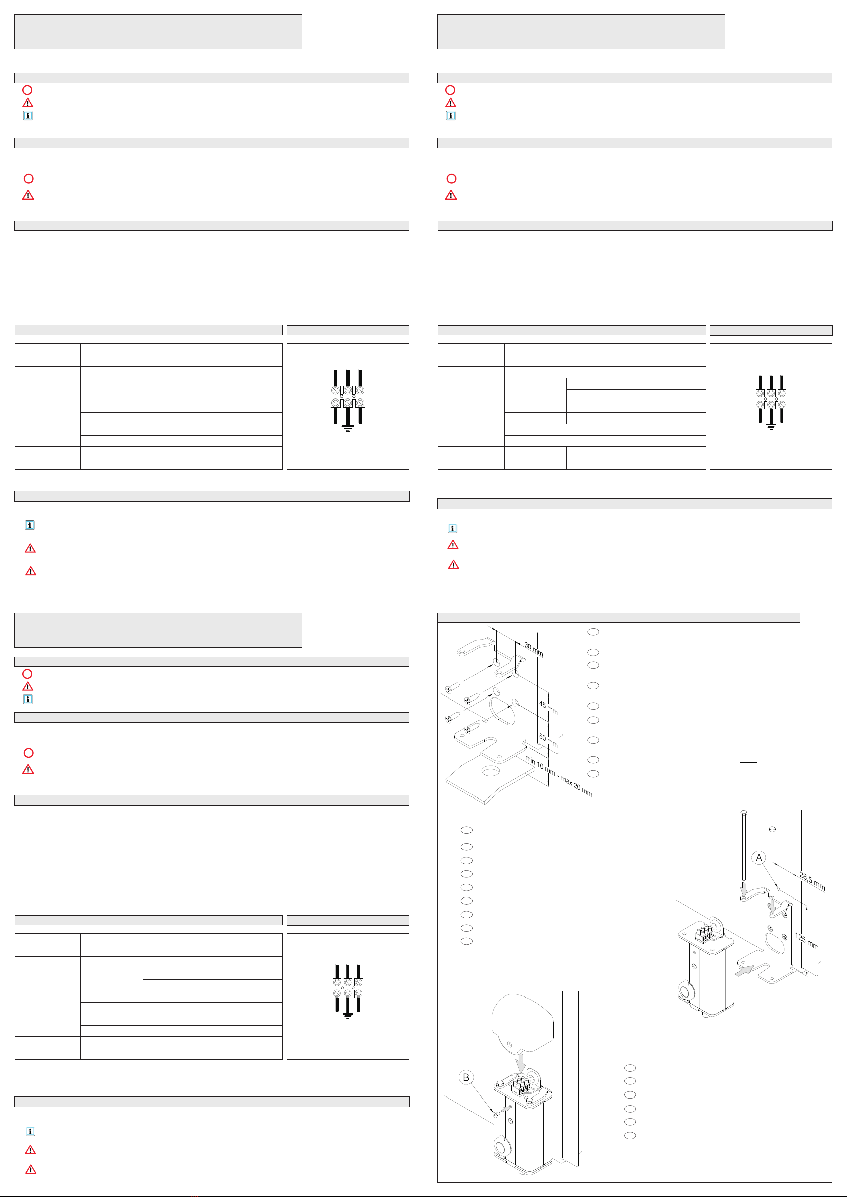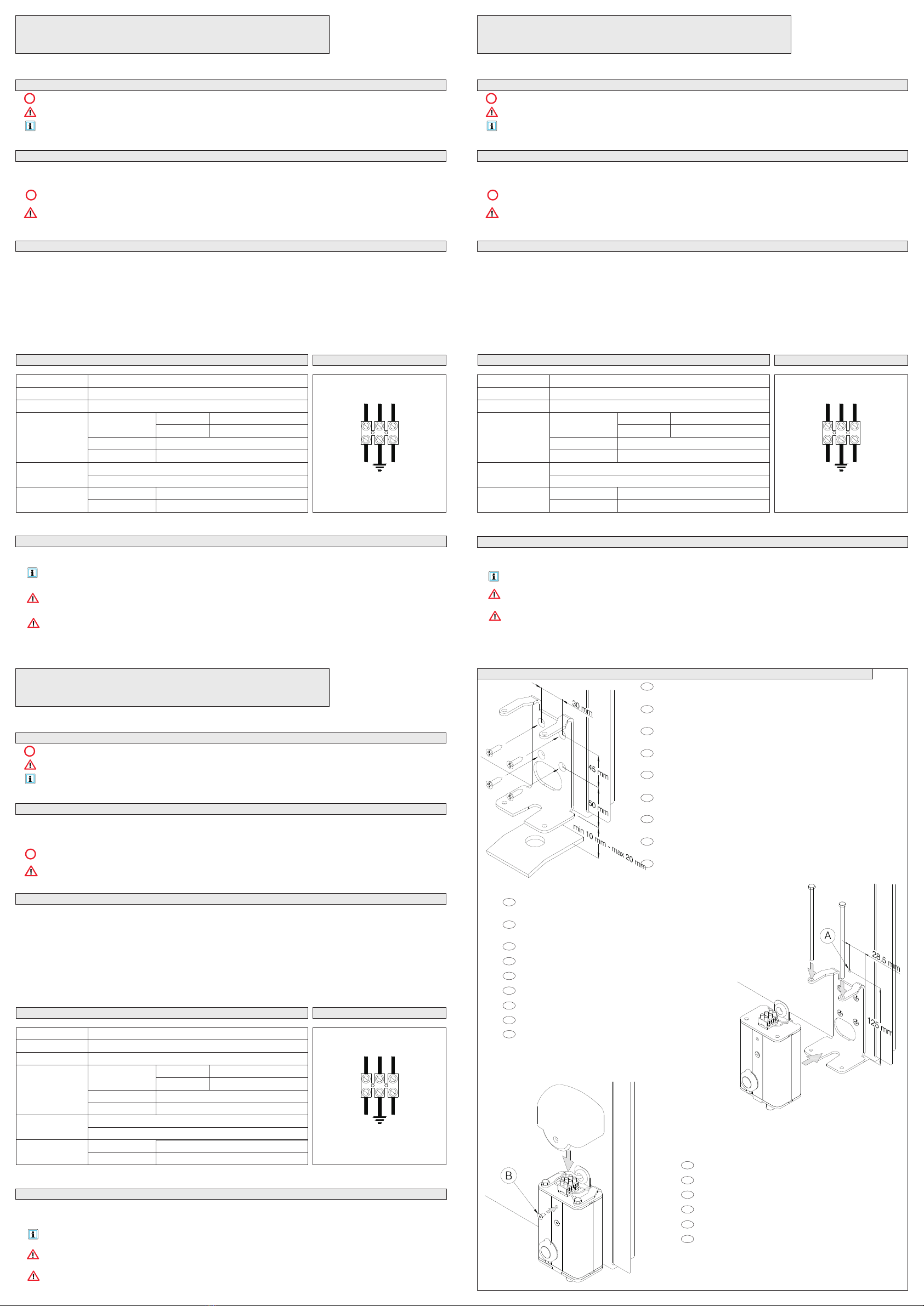
f.3.1 ElektrischeAnschlüsse vornehmen. (sieheAbschnitt „e.Anschlüsse“)
Efectuar las conexiones eléctricas. (véase la sec. “e. Conexiones”)
Wykonaæ po³¹czenia elektryczne. (zobacz sekc. “e.Po³¹czenia”)
f.3.2 Die Schutzhaube einsetzen und mit der Schraube (B) befestigen
Poner la caperuza protectora, afirmándola con el tornillo (B)
Za³o¿yæ os³onê zabezpieczaj¹c¹ mocuj¹c j¹ za pomoc¹ œruby (B)
f.2.1 Das Loch für den Durchgang der Verbindungskabel (A) bohren und dabei die Maße in ABB. 2
berücksichtigen.
Preparar el agujero para hacer pasar los cables de conexión (A), haciendo referencia a las
cotas indicadas en la FIG.2
Wywierciæ otwór na kable po³¹czeniowe (A), przestrzegaj¹c wielkoœci podanych na RYS.2
f.2.2 Den Schlosskörper positionieren und in die Frontseite einsetzen.
Posicionar el cuerpo del cerrojo eléctrico, insertándolo por la parte frontal
Umieœciæ korpus zamka wsuwaj¹c go od przedniej strony
f.2.3 Die Gewindestifte wieder in ihre Sitze einsetzen.
Volver a poner los tirantes roscados en los alojamientos previstos
Ponownie umieœciæ gwintowane ciêgna w stosownych gniazdach
f.1.1 Den Bügel an das Tor entweder schweißen oder mit Hilfe der Schrauben an den
entsprechenden Löchern befestigen (*)
Fijar el estribo a la cancela soldándolo o mediante tornillos en correspondencia de
los puntos previstos. (*)
Umocowaæ wspornik bramy zgrzewaj¹c go lub przykrêcaj¹c œrubami w stosownych
otworach. (*)
f.1.2 Die in ABB. 1 angegebenen Maße berücksichtigen und darauf achten, dass der
Bügel senkrecht positioniert ist.
Ajustarse a las cotas indicadas en la FIG.1 cerciorándose de que el estribo esté
puesto vertical
Przestrzegaæ wielkoœci podanych na RYS.1 upewniaj¹c siê, ¿e wspornik jest
umieszczony pionowo
(*) Falls das Zubehörteil E.LOCK-SE für die externe Entriegelung verwendet wird, die
Löcher in das Tor bohren, bevor der Bügel angebracht wird.
Si se utiliza el accesorio E.LOCK-SE de desbloqueo externo, taladrar la cancela antes
de fijar el estribo.
Je¿eli ma byæ zainstalowany dodatkowy osprzêt w postaci E.LOCK-SE zewnêtrznego
odblokowania, wywierciæ otwór przed umocowaniem wspornika.
DE
DE
DE
ES
ES
ES
ES
ES
ES
ES
ES
PL
PL
PL
PL
PL
PL
PL
PL
850 g
Pag.4 di 4
Manuale di Installazione
IST_ E.LOCK DE
Rev. 1101
Pag. 1 di 4
Meldet wichtige Anweisungen, die aufmerksam zu lesen sind;
Meldet Anweisungen, die die Sicherheit betreffen;
Meldet Informationen, die sich direkt an den Endbenutzer richten.
Der Schnappverschluss wird als Türverriegelungsvorrichtung bei Automatiken von Falttoren verwendet.
Anwendungen die nicht den Anweisungen des Elektroschlosses E.LOCK entsprechen oder Installationen, die nicht laut
Anweisungen des vorliegenden Handbuchs vorgenommen werden, können den einwandfreien Betrieb der Vorrichtung
beeinträchtigen.
Die Installation des Elektroschlosses E.LOCK muss von qualifizierten Installateuren vorgenommen werden.
c.1Das Elektroschloss E.LOCK wird in seinem Sitz senkrecht positioniert. Die Schutzhaube der Kontakte muss nach oben
gerichtet sein.
c.2Das Elektroschloss E.LOCK besteht aus einem am Tor zu befestigenden verzinkten Stahlbügel und einem
Elektroschlosskörper, der einen Magnet und eine Entriegelungsvorrichtung enthält.
c.3Bei Stromausfall oder defekter Vorrichtung, kann das Elektroschloss über einen Schlüssel von der Torinnenseite aus (oder
von außen entriegelt werden (* ).
E.LOCK-A
E.LOCK
Schutzklasse
115 Vac 60Hz
Magnet
Mit Schlüssel – 90° nach links
Intensität der 100 %
Mit Schlüssel – 90° nach rechts
IP54
280VA (Spitzenstrom) - 27VA (Betrieb)
220 Vac 50Hz
Riegel
Entriegelung
Maximaler Hub 15mm
Durchmesser 12mm
Gewicht
Extern (*)
Intern
Stromaufnahme
Speisespannung
Maße 80 x 55 x 155 mm
f.1Wartung
Das Elektroschloss E.LOCK ist praktisch wartungsfrei. Es genügt, wenn es regelmäßig kontrolliert wird (alle 6 Monate).
Dabei sollten eventuelle Fremdstoffe entfernt und das Schloss gereinigt werden. (Achtung: das Gerät wird mit Strom
versorgt).
Eventuelle Änderungen an der Vorrichtung können gefährlich sein.
Jegliche Wartungsarbeiten dürfen nur von qualifizierten Installateuren vorgenommen werden.
ELEKTRISCHER SCHNAPPVERSCHLUSS
Mod. E.LOCK / E.LOCK-A
a. Erläuterung der Symbole:
g. Montage des Elektroschlosses / Montaje del cerrojo eléctrico / Monta¿ elektrycznego zamka
b. Gebrauchsbestimmung
c. Beschreibung
d. Technische Eigenschaften e. Anschlüsse
f. INFORMATIONEN FÜR DEN ENDBENUTZER
(*) E.LOCK-SE Externes Entriegelungsset 50mm Option.
E.LOCK*
E.LOCK-A*
*Auf jeden Fall erden
FIG.1
FIG.3
FIG.2
F N
MAGNET
115Vac
220Vac
DE
DE
DE
DE
DE
Installation Manual
IST_ E.LOCK PL
Rev. 1101
Pag. 3 di 4
Installation Manual
E.LOCK ES
Rev. 1101
Pag. 2 di 4
Sygnalizuje te fragmenty podrêcznika, które nale¿y przeczytaæ ze szczególn¹ uwag¹;
Sygnalizuje fragmenty dotycz¹ce bezpieczeñstwa;
Sygnalizuje informacje skierowane do koñcowego u¿ytkownika.
Indica las partes del manual a leer detenidamente
Indica partes relacionadas con la seguridad;
Indica la información dirigida al usuario final (utilizador).
;
L'elektryczny zamek zapadkowy jest stosowany jako mechanizm blokuj¹cy skrzyd³o w automatycznych bramach otwieranych
skrzyd³owo.
U¿ytkowanie elektrycznego zamka E.LOCK w sposób odmienny od opisanego w niniejszym podrêczniku lub
nieprawid³owo wykonana instalacja mog¹ ujemnie wp³yn¹æ na prawid³owe funkcjonowanie urz¹dzenia.
Elektryczny zamek E.LOCK powinien byæ zainstalowany przez wykwalifikowanych instalatorów.
El cerrojo eléctrico por gravedad se utiliza como dispositivo de bloqueo de la hoja en sistemas de automatización de cancelas
de libro .
Utilizaciones del cerrojo eléctrico E.LOCK diferentes de la susodicha o instalaciones no realizadas de conformidad con
cuanto descrito en el siguiente manual pueden perjudicar el funcionamiento correcto del aparato.
El cerrojo eléctrico E.LOCK deben instalarlo solamente instaladores cualificados.
c.1
styki zosta³a zamontowana w górnej czêœci.
c.2Elektryczny zamek E.LOCK sk³ada siê ze wspornika z ocynkowanej stali, który powinien byæ umocowany do bramy oraz z
korpusu zamka, w którym znajduje siê magnes oraz mechanizm odblokowania.
c.3W razie braku napiêcia lub awarii urz¹dzenia, mo¿na uruchomiæ elektryczny zamek odblokowuj¹c go za pomoc¹ klucza od
strony wewnêtrznej bramy i, na ¿yczenie, równie¿ od strony zewnêtrznej (*).
Elektryczny zamek E.LOCK powinien byæ pionowo umieszczony w gnieŸdzie zwracaj¹c uwagê, aby os³ona zabezpieczaj¹ca
c.1
contactos en la parte superior.
c.2El cerrojo eléctrico E.LOCK se compone de un estribo de acero galvanizado, que se tiene que fijar a la cancela, y del cuerpo
del cerrojo eléctrico que contiene el imán y el dispositivo de desbloqueo.
c.3Al faltar tensión eléctrica o si el dispositivo no funciona, es posible accionar el cerrojo eléctrico mediante un desbloqueo con
llave desde el lado interior de la cancela y bajo pedido también desde el lado externo (*).
El cerrojo eléctrico E.LOCK se tiene que poner en vertical, prestando atención en montar la caperuza protectora de los
ELEKTRYCZNY ZAMEK ZAPADKOWY
Mod. E.LOCK / E.LOCK-A
CERROJO ELÉCTRICO POR GRAVEDAD
Mod. E.LOCK / E.LOCK-A
a. :Symboles
a. :Key to symbols
b. Przeznaczenie
b. Uso previsto
c. Opis
c. Descriptiòn
g.1
Elektryczny zamek E.LOCK nie wymaga szczególnej konserwacji, jednak zaleca siê przeprowadzanie okresowych
kontroli (co 6 miesiêcy)..
Zaleca siê usuwanie ewentualnego zanieczyszczenia za pomoc¹ okresowego czyszczenia.(Uwaga: urz¹dzenie pod
napiêciem).
Ewentualne modyfikacje urz¹dzenia mog¹ stworzyæ niebezpieczne sytuacje.
Wszelkie zabiegi konserwacyjne urz¹dzenia powinny byæ wykonywane przez wykwalifikowanych instalatorów
Konserwacja
g. INFORMACJE DLA KOÑCOWEGO U¯YTKOWNIKA
g.1
El cerrojo eléctrico E.LOCK no exige mantenimiento especial, sin embargo se aconseja efectuar una inspección
periódica (cada 6 meses).
Es buena norma quitar eventuales sustancias extrañas efectuando una limpieza periódica. (Atención: aparato bajo
tensión eléctrica).
Eventuales modificaciones del aparato pueden engendrar situaciones peligrosas. Cualquier operación de
mantenimiento del aparato tiene que ser efectuada por instaladores cualificados.
Mantenimiento
g. Información para el usuario final
850 g
850 g
E.LOCK-A
E.LOCK-A
E.LOCK
E.LOCK
Stopieñ ochrony
Grado de protección
115 Vac 60Hz
115 Vac 60Hz
Magnes
Imán
Mit Schlüssel – 90° nach links
Con llave - rotación 90° a la izq
Wspó³czynnik
Intensidad de utilización
100 %
100 %
Mit Schlüssel – 90° nach rechts
Con llave - rotación 90° a la derecha
IP54
IP54
280VA (szczytowe) - 27VA (funkcjonowanie)
280VA (pico) - 27VA (funcionamiento)
220 Vac 50Hz
220 Vac 50Hz
Ko³ek
Perno
Odblokowanie
Desbloqueo
Maksymalny tor 15mm
Carrera máxima 15mm
Œrednica 12mm
Diámetro 12mm
Ciê¿ar
Peso
Zewnêtrzny (*)
Externo (*)
Wewnêtrzne
Interno
Pobór mocy
Corriente absorbida
Napiêcie
zasilania
Tensión de
alimentación
Wymiary
Medidas
80 x 55 x 155 mm
80 x 55 x 155 mm
d. Dane techniczne
d. Características Técnicas
e. Po³¹czenia
e. Conexiones
(*) E.LOCK-SE Zestaw odblokowania zewnêtrznego 50mm opcja.
(*) E.LOCK-SE Kit desbloqueo externo 50mm opcional.
E.LOCK*
E.LOCK-A*
E.LOCK*
E.LOCK-A*
*Nale¿y zawsze pod³¹czyæ uziemienie
*Conectar siempre la puesta a tierra
F N
MAGNES
115Vac
220Vac
F N
IMÁN
115Vac
220Vac