Beninca IRI.KPAD.C User manual

IRI.KPAD.C
UNIONE NAZIONALE COSTRUTTORI
AUTOMATISMI PER CANCELLI, PORTE
SERRANDE ED AFFINI
L8543208
06/2017 rev 2


3
5
3
1
7
9
*
6
4
2
8
0
#
ENTER
LED
133 mm
29 mm 85 mm
1 2

4
43
5

5
6
50
70
Ø 5
7
8

6
9
OK!
NO!
3,5x10mm TORX
NO!
7
10
12/24Vac/dc
12/24Vac/dc
12/24
Vac/dc
N.O 60Vac/dc
500mA max
N.O 60Vac/dc
120mA max
- 24V +
OPEN/PP
CONTROL UNIT
230Vac
JP1
Open
JP1
Close
JP1
JP1
STAND-ALONE MODE
11
12/24Vac/dc
12/24Vac/dc
12/24
Vac/dc
N.O 60Vac/dc
500mA max
N.O 60Vac/dc
120mA max
- 24V +
OPEN/PP
CONTROL UNIT
230Vac
JP1
Open
JP1
Close
JP1
JP1
STAND-ALONE + POWER MODE
8
BE-REC
P1
L2
L3
1ch
2ch
24V
TX
ac
dc
L1
max. 40 m
2x0,5 mm2
TX
12/24Vac/dc
TX
12/24Vac/dc
TX
12/24Vac/dc
TX
12/24Vac/dc
1
2
3
4
BE-REC
P1
L2
L3
1ch
2ch
24V
TX
ac
dc
L1
max. 40 m
2x0,5 mm2
TX
12/24Vac/dc
TX
12/24Vac/dc
TX
12/24Vac/dc
TX
12/24Vac/dc
123
4
12
REMOTE MODE

9
ITA AVVERTENZE
E’ vietato l’utilizzo del prodotto per scopi o con modalità non previste nel presente manuale. Usi non corretti possono essere causa di danni al
prodotto e mettere in pericolo persone e cose.
Si declina ogni responsabilità dall’inosservanza della buona tecnica nella costruzione dei cancelli, nonché dalle deformazioni che potrebbero
verificarsi durante l’uso.Conservare questo manuale per futuri utilizzi.
Questo manuale è destinato esclusivamente a personale qualificato per l’installazione e la manutenzione di aperture automatiche.
L’installazione deve essere effettuaua da personale qualificato (installatore professionale, secondo EN12635), nell’osservanza della Buona Tecnica
e delle norme vigenti. Verificare che la struttura del cancello sia adatta ad essere automatizzata.
L’installatore deve fornire tutte le informazioni relative al funzionamento automatico, manuale e di emergenza dell’automazione, e consegnare
all’utilizzatore dell’impianto le istruzioni d’uso.
I materiali dell’imballaggio non devono essere lasciati alla portata dei bambini in quanto fonte di potenziale pericolo. Non disperdere nell’ambiente
i materiali di imballo, ma separare le varie tipologie (es. cartone, polistirolo) e smaltirle secondo le normative locali.
Non permettere ai bambini di giocare con i dispositivi di comando del prodotto. Tenere i telecomandi lontano dai bambini.
Questo prodotto non è destinato a essere utilizzato da persone (bambini inclusi) con capacità fisiche, sensoriali o mentali ridotte, o con mancanza
di conoscenze adeguate, a meno che non siano sotto supervisione o abbiano ricevuto istruzioni d’uso da persone responsabili della loro sicurezza.
Applicare tutti i dispositivi di sicurezza (fotocellule, coste sensibili, ecc.) necessari a proteggere l’area da pericoli di impatto, schiacciamento,
convogliamento, cesoiamento. Tenere in considerazione le normative e le direttive in vigore, i criteri della Buona Tecnica, l’utilizzo, l’ambiente di
installazione, la logica di funzionamento del sistema e le forze sviluppate dall’automazione.
L’installazione deve essere fatta utilizzando dispositivi di sicurezza e di comandi conformi alla EN12978 e EN12453.
Raccomandiamo di utilizzare accessori e parti di ricambio originali, utilizzando ricambi non originali il prodotto non sarà più coperto da garanzia.
Tutte le parti meccaniche ed elettroniche che compongono l’automazione soddisfano i requisiti e le norme in vigore e presentano marcatura CE.
Prevedere sulla rete di alimentazione un interruttore/sezionatore onnipolare con distanza d’apertura dei contatti uguale o superiore a 3 mm.
Verificare che a monte dell’impianto elettrico vi sia un interruttore differenziale e una protezione di sovracorrente adeguati.
Alcune tipologie di installazione richiedono il collegamento dell’anta ad un impianto di messa a terra rispondente alle vigenti norme di sicurezza.
Durante gli interventi di installazione, manutenzione e riparazione, togliere l’alimentazione prima di accedere alle parti elettriche.
Scollegare anche eventuali batterie tampone se presenti.
L’installazione elettrica e la logica di funzionamento devono essere in accordo con le normative vigenti.
I conduttori alimentati con tensioni diverse, devono essere fisicamente separati, oppure devono essere adeguatamente isolati con isolamento
supplementare di almeno 1 mm. I conduttori devono essere vincolati da un fissaggio supplementare in prossimità dei morsetti.
Ricontrollare tutti i collegamenti fatti prima di dare tensione.
Gli ingressi N.C. non utilizzati devono essere ponticellati.
SMALTIMENTO
Come indicato dal simbolo a lato, è vietato gettare questo prodotto nei rifiuti domestici in quanto alcune parti che lo compongono potrebbero
risultare nocive per l’ambiente e la salute umana, se smaltite scorrettamente. L’apparecchiatura, pertanto, dovrà essere consegnata in ade-
guati centri di raccolta differenziata, oppure riconsegnata al rivenditore al momento dell’acquisto di una nuova apparecchiatura equivalente. Lo
smaltimento abusivo del prodotto da parte dell’utente comporta l’applicazione delle sanzioni amministrative previste dalla normativa vigente.
Le descrizioni e le illustrazioni presenti in questo manuale non sono impegnative. Lasciando inalterate le caratteristiche essenziali del prodotto il fabbricante
si riserva il diritto di apportare qualsiasi modifica di carattere tecnico, costruttivo o commerciale senza impegnarsi ad aggiornare la presente pubblicazione.

10
1) IRI.KPAD.C
1.1) DESCRIZIONE
Pulsantiera Digitale Programmabile per il comando di automatismi per cancelli e simili. Può essere utilizzata in due differenti modalità:
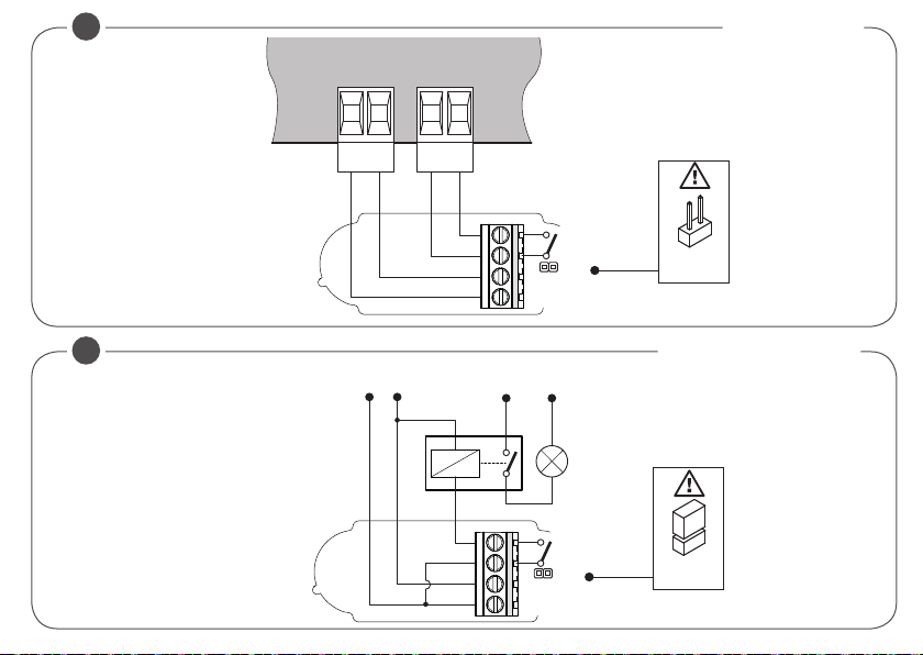
STAND-ALONE MODE:
Richiede alimentazione 12/24 Vac/dc, dispone di 1 contatto N.O. per il controllo di una centrale di comando o altro dispositivo.
L'immissione di un codice numerico valido comporta l'invio di un codice che aziona il contatto di uscita.
Nel caso si renda necessario è possibile utilizzare un relè ausiliario per il controllo diretto di un dispositivo a tensione di rete. In
questo caso assicurarsi che il tipo di relè utilizzato sia compatibile con la tensione di alimentazione di IRI.KPAD. Fate riferimento
alle Fig. 10/11.
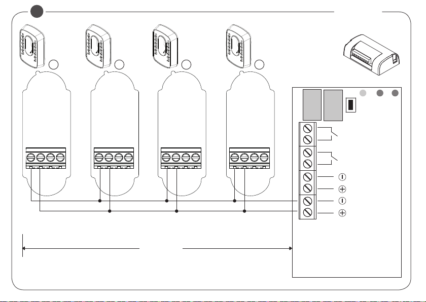
REMOTE MODE:
Richiede la connessione ad un dispositivo BE.REC (Fig.12). Tutti i codici vengono memorizzati nella memoria del dispositivo
BE.REC. L’immissione di un codice numerico valido comporta l’invio di un codice criptato alla ricevente BE.REC, il codice, se
convalidato, comporta la commutazione del relè 1 o 2 a seconda dell'impostazione.
Di conseguenza è la modalità di utilizzo della IRI.KPAD.C che garantisce maggior sicurezza e flessibilità rispetto all’utilizzo del
contatto N.O. integrato. Fate riferimento alla Fig.12 per la connessione al dispositivo BE.REC*.
L'utilizzo del ricevitore BE.REC consente inoltre l'utilizzo di alcune funzioni avanzate descritte nel manuale BE.REC:
- inserimento codici a scalare
- cancellazione di un codice
- cancellazione di tutti i codici con una specifica cifra iniziale
- riabilitazione di tutti i codici con una specifica cifra iniziale
- riabilitazione di tutti i codici disabilitati
* Installare BE.REC in un luogo sicuro, non accessibile dall'esterno.
Altre caratteristiche:
• Retro-illuminazione a LED.
• Composizione codice da 4 a 9 cifre.
• Numero di tasti da 0 a 9 più tasto # di conferma.
• Possibilità di impostazione password accesso, codici a scalare, eliminazione codici singoli.
• Buzzer per indicazioni sonore.
Table of contents
Languages:
Other Beninca Keypad manuals


