BenQ PDP46W1 - 46W1 - 46" Plasma Panel User manual

Table of Contents
1. Safety Guidelines: ------------------------------------------------------------------------------------- 1
2. Before Use:-------------------------------------------------------------------------------------------- 2
2.1 Open the Package
2.2 Installation
3. Safety -------------------------------------------------------------------------------------------------- 3
4. Product Features -------------------------------------------------------------------------------------- 9
5. Standard Components-------------------------------------------------------------------------------- 10
6. Names and Functions of Parts: --------------------------------------------------------------------- 11
6.1 Side View
6.2 Front View
6.3 Rear View
6.4 Remote Controller
7. Connection to External Equipment----------------------------------------------------------------- 20
7.1 PC Module
7.2 PC Module + Video Module
7.3 PC Module + Enhanced PC Module
7.4 Connection to External Laud Speakers
8. Basic Operation--------------------------------------------------------------------------------------- 24
8.1 Power ON/OFF
8.2 Selection of Input Mode
8.3 OSD Option Adjustment
8.4 Sound Adjustment
8.5 Zooming of the Screen
8.6 Other Functions
8.7 OSD Functions
9. Optional Accessories--------------------------------------------------------------------------------- 33
10. Specifications ----------------------------------------------------------------------------------------- 34
11. Factory Settings--------------------------------------------------------------------------------------- 34
12. Cleaning and Simple Troubleshooting------------------------------------------------------------- 36
i

1. Safety Guidelines:
Caution: Use a power cable is properly grounded. Always use the AC cords listed below for
each area:
USA …………………… UL
Canada………………….. CSA
Germany…………………VDE
Britain……………………BASEC/BS
Japan…………………….Electric Appliance Control Act
FCC Information
This equipment has been tested and found to comply with the limits for a Class B digital
device, pursuant to part 15 of the FCC Rules. These limits are designed to provide reasonable
protection against harmful interference in a residential installation. This equipment generates,
uses, and can radiate radio frequency energy, and if not installed and used in accordance with
the instructions, may cause harmful interference to radio communications. However, there is no
guarantee that interference will not occur in a particular installation. If this equipment does
cause unacceptable interference to radio or television reception, which can be determined by
turning the equipment off and on, the user is encouraged to try to correct the interference by
one or more of the following measures:
- Reorient or relocate the receiving antenna.
- Increase the separation between the equipment and receiver.
- Connect the equipment into an outlet on a circuit different from that to which
the receiver is connected.
- Consult the dealer or an experienced radio/TV technician for help
FCC Warning
To assure continued FCC compliance, the user must use the provided grounded
power supply cord and the provided shielded video interface cables to connect to
this equipment. Also, any unauthorized changes or modifications to this equipment
would void the user’s authority to operate this device.
1

2. Before Use:
The product is a 46” WVGA (wide-screen with VGA resolution) Plasma Display with the
features of super thinness, high quality, flat display and non-radiation. It has passed the
Class-B EMC test and the UL and CSA safety certifications, and is an ideal product for
individual users and commercial exhibitioners.
The product is a precise electronic product. Users shall read the following instructions
carefully to bring the performance of the product into full play:
2.1 Open the Package:
The product is packaged in a carton together containing a host and other standard
accessories. The optional accessories are packed separately in another carton.
The weight of the host is about 37 kg. Since the size of the host is big, it is
recommend moving it by two persons.
The protective glass and the glass substrate are installed on the front of the product.
Since both glasses are broken and scraped easily, move then gently. Don’t put the
glasses with their faces downward without protecting them with pads.
When opening the carton, check whether the product is in good condition and all the
parts and components are packed without shortage.
Whenever possible, use the handles on the back of the Display for transport.
2.2 Installation:
Read the User Manual carefully before conducting the installation.
The power of the product is about 340~350W, somewhat higher than ordinary TV
sets. Use the jack exclusively designed for the product. When an extended line is
required, consult with your service agent to select an extended line with higher power
to avoid any risk.
The product shall be installed on a flat ground to avoid declining. The distance
between the back of the product and the wall shall be maintained for proper
ventilation.
Don’t install the product in kitchen, bathroom and other places with higher smoke,
humidity or dust to so as not to shorten the service life of the electronic components.
Please ensure the product be installed horizontally, any 90°clockwise or
counterclockwise installation may induce poor ventilation and components damage
should be avoided.
To protect the screen and elongate the usage life, do not hold on a static picture for a
long time.
In order to get the best warranty, the product must be installed by specific technician
from distributor or authorized agent.
2

3. Safety:
Safety of operators is taken into consideration at the phrase of design and manufacturing, but
inappropriate operation may cause electric shock or fire. To prevent the product from being
damaged, the following rules shall be observed for the installation, use and maintenance of the
product. Read the following safety instructions before starting the operation.
The User Manual uses the following symbols to ensure a safe operation and prevent any
damage to operators or properties:
WARNING--- Ignorance or inappropriate use may cause damage
or vital errors to operators.
ATTENTION--- Ignorance or inappropriate use may cause injury
or material damage.
Examples:
Prohibition
Warning (Attention) symbol (indicating “Electric Shock”).
WARNING
Don’t install the product on an unstable ground:
Don’t install the product on an swinging or declining ground;
Otherwise it may drop and cause damage.
Only the marked power source can be used for the product:
The power source other than the marked one may cause fire or
electric shock.
3

Keep the product away from moisture:
* Don’t install the product close to water.
* When the product is used close to windows or
outdoors, keep it away from water.
* When water penetrates into the product, stop the
operation; unplug the connector and contact with your
dealer. Continuous use in this case may cause fire or
electric shock.
WARNING
Don’t put water containers or small metal
objects on the top of the product:
* Don’t put any water-injected cups, small potted plants,
cosmetics, medicine liquid, small containers, or metal
objects on the top of the product. The spoiled water
may cause short circuit, fire or electric shock when it
penetrates into the housing of the product.
Don’t damage the power cable:
Don’t damage or change the power cable. Heavy
objects, heat or tensile force may damage the power cable
and cause fire or electric shock.
Don’t change or open the back cover:
Changing the product may cause fire or electric shock.
Don’t remove the back cover of the product to avoid
possible electric shock.
Contact the manufacturer when inspection or adjustment is required.
Don’t use the product when any abnormality occurs:
Continuous use of the product in the case of smoking or
odor spreading may cause fire or electric shock. Unplug
the connector and contact the manufacturer immediately.
Don’t try to repair the product by yourself to avoid any
risk.
4

WARNING
Don’t drop or damage the housing:
In the case the product is dropped and the housing is
damaged, the internal components may function
abnormally. Unplug the connector immediately and
contact the manufacturer for repair. Continuous use of
the product may cause fire or electric shock.
WARNING
Don’t touch the power jack during lightening:
Don’t touch the power jack during lightening to avoid
electric shock.
ATTENTION
Don’t install the product close to smoke or moisture:
Fire or electric shock may be caused when the product is
installed close to smoke or moisture.
Don’t installed the product in a place with
heavy dust or high humidity:
Fire or electric shock may be caused when the product is
installed in a place with heavy dust or high humidity.
Instructions about moving the product:
Make sure that the power connector and other plugs are
all unplugged before moving the product. The product
shall be moved by at least two persons.
5

The power cable shall be kept away from heat
sources:
The heat produced by any heat source may fuse the
covering of the power cable.
Hold the power connector when remove the
power cable:
Pulling the power cable may damage the wires inside the
cable and cause fire or electric shock.
Don’t touch the connector with wet hands:
Electric shock may be caused in this case.
Unplug the connector
ATTENTION
Insert batteries in accordance with
instructions:
Insert the batteries with correct polarities (positive + and
negative -). Incorrect polarities may case breakage and
leakage of the batteries, hurt operators and contaminate
the remote controller. Don’t charge the batteries
attached with the product to avoid any risk.
Don’t put any object on the vents:
Blocking the vents may raise the internal temperature and
make the housing hot or cause fire.
Touching the hot housing may hurt operators. Don’t
install the product in a place with narrow space or bad
ventilation. Don’t cover the vents with towels, blankets
or dusters.
When the product is unused for a long time:
Unplug the power connector and other plugs when the
product will not be used for a long time.
Unplug the connector
6

3.1 Read all safety instructions and the User Manual before using the product.
3.2 The safety instructions and User Manual shall be maintained in good condition for future
use.
3.3 Special attention shall be paid to the warnings on the User Manual.
3.4 The User Manual shall be observed when using the product.
3.5 Unplug the power connector before cleaning the product. A wet cloth is sufficient for
the cleaning of the product and don’t use liquid or spraying cleaner for cleaning purpose.
3.6 Use the accessories recommended by the manufacturer to avoid any risk.
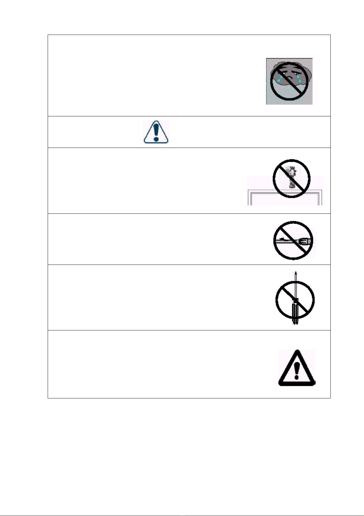
3.7 Keep the product away from any water source. When moving the product from lower
temperature to high temperature environments, drops of water may condense on the
housing. Don’t turn on the Display immediately so as not to cause fire, electric shock or
other risks.
3.8 Don’t install the product on unstable wagons, racks or tables to avoid falling, hurt or
material damage. The installation of the product shall be conducted in accordance with
the instructions of the manufacturer and by using the support recommended by the
manufacturer.
3.9 When installing the product on a wagon, emergency stop or forceful push of the wagon is
prohibited. It is also not allowed to drive the wagon through an uneven ground to avoid
falling, hurt or material damage.
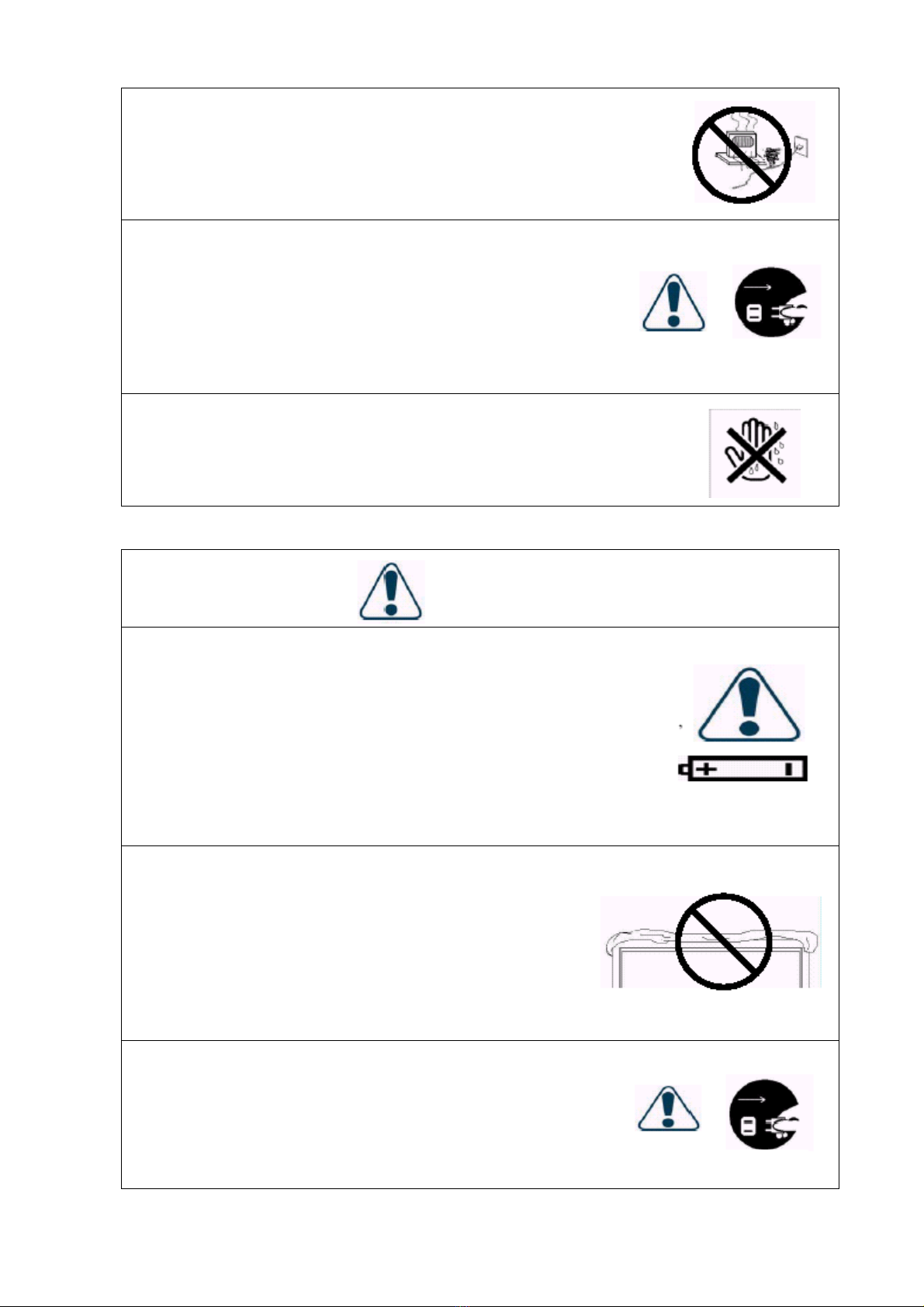
3.10 The openings on the back of the product provide a ventilation function and can ensure the
reliability of the operation from being affected by overheats. The vents shall not be
blocked or closed, especially when the product is installed on your bed, sofa, blanket or
other similar surfaces. Expect for a good ventilation condition is available, don’t
installed the product in an embedded rack or bookcase. The installation shall be
conducted in accordance with the instructions of the manufacturer.
To ensure good ventilation, a distance of more than 10cm shall be maintained
between the Display and any other furniture.
3.11 Energize the product with the voltage specified on the power supply label. Contact your
dealer or local power station when you don’t know the voltage of your power source.
3.12 The three-wire power connector attached to the product shall only plug into the jack with
a grounding terminal. When you encounter any difficult in the plugging of the power
connector, contact electricity technicians for assistance and don’t damage the ground
terminal of the power connector.
3.13 The power cable shall be fixed along with its patch. Don’t lead the power cable through
the passageway or have it pressed by other objects. Special attention shall be paid to the
wiring at the door and of the power connector and other plugs and jacks.
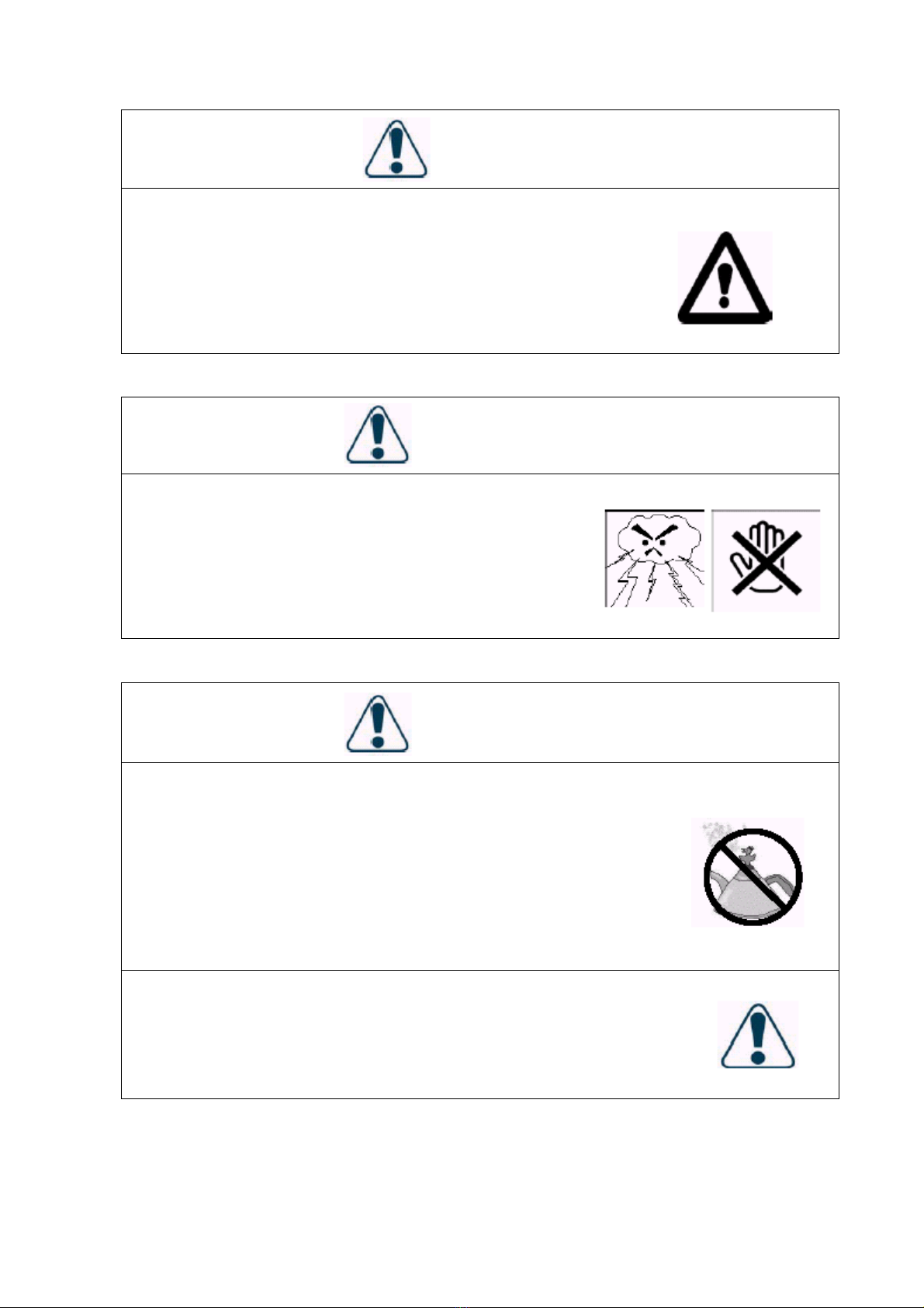
3.14 when it lightens or the product will not be used for a long time, remove the power cable
and all other cables from the jacks to avoid any damage caused by the lightning or the
surge of the power source.
3.15 Don’t overload the power jack. Using extended lines or the jacks of other appliances
may cause fire of electric shock.
3.16 Don’t put any object from the vents; otherwise, high voltage may be induced and causes
short circuit, fire or electric shock. Water sprayed to the product is prohibited.
3.17 Opening or removing the back cover may expose you in high voltage or other risks.
When repair is required, contact qualified service staffs and don’t repair the Display by
yourself.
3.18 Unplug the power connector and contact with qualified service staffs when the following
incidents occur:
The power supply or connector fails.
Liquid sprays or any object drops into the Display.
7

The Display exposes in the rain.
When the Display cannot operate in normal condition, adjust it in accordance with
the User Manual. It may take more time to remove the damage caused by
inappropriate adjustment.
The Display drops or damages under any circumstances.
The performance of the Display changes substantially.
3.19 When it is required to replace parts, make sure that the service staffs use the parts
specified by the manufacturer or with the features same as the replaced parts. Unqualified
substitutes may cause fire, electric shock or other risks.
3.20 When the repair is completed, the service staffs shall conduct a safety inspection to
ensure normal operation of the product.
3.21 A distance of at least 1 meter shall be maintained between the product and any heat
source, such as radiator, heater, electrical oven, amplifier and other heat producing
devices.
3.22 Turn off the power of the product to avoid electric shock before connecting it to other
devices, such as VCR or PC.
3.23 Only use the special cable approved by manufacturer to avoid any electric shock.
3.24 The rated voltage is AC 100V~120V/220V~240V.The power source used shall have such
voltage. It is recommended to use the power cable specified by you dealer for the sake
of safety and EMC.
3.25 The power cable must be replaced when using different voltage from that specified in the
User Manual. For more information, contact your dealer.
3.26 Operating environment:
Temperature 32oF~104oF (0oC ~ 40oC)
Humidity 20% to 85% non-condensing
Atmospheric pressure 800 to 1100hPa
8

4. Product Features:
The machine uses a Plasma Display Panel with a thickness of 9.8cm. It provides quality image
displays and is an ideal choice for multimedia applications.
4.1 Available for multiple input signals:
The standard PC module provides RGB (D-SUB15 PIN) and digital DVI input
connectors, and a RS-232 communication connector (D-SUB 9 PIN MALE).
The Video module provides composite video(RCA),S-video (DIN 4P) and
component video (RCA) input connectors, and a composite video (BNC) output
connector. It supports the quality images input of DVD and HDTV
(480P/720P/1080i), as well as the images of TV systems such as NTSC, PAL and
SECAM. The Video module also provides two sets of stereo input connectors
(RCA).
The enhanced PC module provides two sets of RGB input connectors (one set each
for D-SUB15 PIN and RGBHV 5 line BNC) and one set of RGB output connectors
(D-SUB15 PIN). A set of PC sound input connectors is also provided.
The machine supports PC image quality up to XGA (1024X768) with a vertical
frequency of 85Hz.
4.2 Power Management Function: The machine provides an automatic power saving
function.
4.3 Fan-free Design: The power of the machine is effectively lowered and does not require a
fan for ventilation, eliminating any bothersome noise that may be generated by fans.
4.4 Others:
PIP Function: The user may watch video while working with his or her PC.
The machine has a set of built-in 2.0W loudspeakers, and can connect to external
10W+10W loudspeakers.
The Machine provides high, medium and low color temperature options. The user
may customize their favorite color temperature.
The user may work with the video module or enhanced PC module to expand the
applications of the machine to meet any special demands.
9

5. Standard Accessories:
User Manual x 1
Power Cord x 1
Note: Depending on the shipping areas, the
actual attached to the product might
be different.
S- Video cable x 1
D-sub 15 PIN Cable x 1
AV- Cable x 1
Component- Cable x 1
Battery UM-4 x 2
Remote controller x 1
10

6. Names and Functions of Parts:
6.1 Side View:
Power
j
ack on the wall
Power jack
Power cable
Power switch
Plug the power cable attached to the product into the power jack on the right side of
the product. Plug the other end of the power cable into the power jack on the wall.
Press the power switch (0: Off, 1: On). The power indicator in the front of the
Display lights red, indicating that the display is in a standby state.
11

6.2 Front View:
(1) Remote control window: The window with a power indicator and IR receiving sensor
are used for indicating power status and receiving remote control signals.
The indicator shows whether the power of the Display is turned on.
Indicator ON (red) Standby state.
Indicator ON (green) Power ON state.
Indicator flashing (red/green) alternately: Power Saving state
(2) Button: The functions of the buttons are described as follows:
INPUT:Select appropriate signal source directly. (Depending on the module, the
available signal source options may be different)
A. PC Module: RGB 1→RGB 2 (circular display).
B. PC Module + Video Module:
RGB 1→RGB 2→AV1→S-Video→Y Cb/Pb Cr/Pr (circular display).
C. PC Module + Enhanced PC Module:
RGB 1→RGB 2→RGB 3→RGB 4 (circular display).
Note: When pressing this button to display “OSD Menu”, the signal sources can be
selected by using the ▲/▼buttons.
MENU: Enter “OSD Menu” and select “OSD Menu” page, which shows in the
following sequence: Display→Image (for PC input) or AV system (for Video
input)→Audio→Language and Screen Saver→Misc.→Status (circular display).
12

▲/▼: A. They are used as up/down buttons in the “OSD Menu” screen.
B. They are used for quick adjustment when “OSD Menu” is not shown on
the screen. The screen shows in the following sequence:
Brightness→Contrast→Volume→Height→Bass→Left/Right Volume
(circular display). The adjustment is made in conjunction with the
“.◄/►.” buttons.
◄/►: A. They are used as left/right buttons in the “OSD Menu” screen. The “►”
button has the function of Enter.
B. They are used for the adjustment of volume with “OSD Menu” is not
shown on the screen. Press “◄” can reduce the volume, while press
“►” can increase the volume..
STANDBY/ON: It is used to activate the Display or bring it into standby state.
WOW Is the trademark of SRS Labs, Inc.
The license to use WOW technology for the product is acquired from
SRS Labs, Inc. when compiling this document.
13

6.3 Rear View:
(1) Speaker Connection Terminals: Each one set of speaker connection terminals on the
left and right sides is used to connect to the speaker with more than 10W(L/R) and
8~15Ω.
(2) Stand.
(3) Four tapped holes for the Stand: Use the standard screws to fix the seat.
(4) Four tapped holes for the wall mount (optional): Use the standard screws to fix the
wall mount.
(5) Transport handles: Use the handles to facilitate the transport. When wall mount is
used, the handles shall be removed before assembling the Display with wall mount.
(6) Four tapped holes for the laud speakers: Use the standard hangers and screws to fix
the optional standard laud speakers.
(7) Signal input terminals: They are used to connect to input devices. Depending on
the selected modules, there are three combinations available for selection:
PC Module
A. D-Sub: Connects to the D-SUB 15 PIN analog output connector of the PC
display card. The Display is used as a PC monitor.
B. DVI: Connects to the DVI-I digital output connector of the PC display card.
The display is used as a PC monitor.
C. RS-232C: is a D-SUB 9 PIN male terminal used as a control port for serial
communication.
14

Video Module
A. CVBS Out: is a composite video output terminal (BNC connector)
connecting to other displays.
B. Audio 2: Is an audio input terminal connecting to the audio output terminal
of the video output device. CVBS In and S-Video share this terminal.
C. CVBS In: is a composite video input terminal (RCA connector) connecting
to the video output terminal of the video output devices.
D. S-Video: is a Y/C S-Video input terminal (DIN 4 PIN) connecting to the
S-output terminal of the video output device.
E. Y/CbPb/CrPr: is a component video input terminal (RCA connector)
connecting to the component output terminal of the video output device.
F. Audio 1: is an audio input terminal connecting to the audio output terminal
of the video output device. The component video and PC input signals share
this terminal.
Enhanced PC Module
A. D-Sub Out: is a D-SUB 15 PIN analog video output connector connecting to
other displays and used as a second output device. (Refer to 7.3.)
B. R/G/B/Hs/Vs: is a five-wire analog input connector (BNC connector)
connecting to the horizontally and vertically synchronous red/green/blue
output terminals of the PC display card.
C. D-Sub In: Connects to the D-SUB 15 PIN analog output connector of the
PC display card. The Display is used as a PC monitor.
D. PC Audio: Connects to the audio output connector of the PC sound card.
The Display can output PC sound.
15

6.4 Remote controller:
1
2
5
6
8
11
13
14
3
4
7
9
10
12
15
6.4.1 Functions of keys:
1. Power: Press this key in the standby state to turn on the Display. Press this
key when turning on the Display to return to the standby state.
2. Video: Press this key to switch the video signal sources. The signal sources
switch in the following sequence: AV1, S-Video, Y Cb/Pb Cr/Pr.
3. (AUTO): A. The Display adjusts the phase, vertical/horizontal position
and color temperature automatically when pressing this key
in PC mode.
B. The Display chooses appropriate video format automatically
when pressing this key in Video mode.
4. PC: Press this key to switch PC signal sources. The signal sources switch in
the following sequence: RGB 1 (PC Module D-Sub Terminal), RGB 2 (PC
Module DVI Terminal), RGB 3 (Enhanced PC Module D-Sub Terminal),
RGB 4 (Enhanced PC Module RGB BNC Terminal).
16

5. Menu◄/Menu►: Switch OSD pages in the following sequence (circular
display):
Display—Image or AV System— Audio-- Language and Screen Saver--- Misc.--- Status
6. Input: Press this key to select the signal sources directly. (Depending on the
module, the available signal source options may be different.)
A. PC Module: RGB 1→RGB 2 (circular display).
B. PC Module + Video Module:
RGB 1→RGB 2→AV1→S-Video→Y Cb/Pb Cr/Pr (circular display).
C. PC Module + Enhanced PC Module: RGB 1→RGB 2→RGB 3→RGB 4
(circular display).
Note: When pressing this button to display “OSD Menu”, the signal sources
can be selected by using the ▲/▼buttons.
7. Wide: Press this key to switch to wide screen. Pressing this key again can
restore the original size of the screen.
8. ▲▼: Use these keys to adjust “OSD Menu” up and down.
9. ◄►: Use these keys to adjust “OSD Menu” left and right.
10. Exit: Press this key to exit “OSD Menu”.
11. Zoom+/ Zoom-: Use these keys to zooming the screen.
12. Vol+/ Vol-: Use these keys to adjust the volume.
13. PIP: Use this key to adjust the size of the sub-picture in the following
sequence:
Sub-picture open (small)→Screen (middle)→Screen (large)→Sub-picture
closed (circular display).
14. Freeze: Press this key to suspend the current screen. The playback system
keeps playing when the screen is frozen. You may press this key again to
continue playing or resume play automatically after one minute.
15. Mute: Press this key to mute the laud speakers. Press it again to restore the
audio output.
17

6.4.2 Insertion of Batteries:
Press here
1. As shown in the above figure, press the position pointed out by the arrow and
push the cover out of its location.
2. Insert two No. 4 batteries in the remote controller as shown in the above
figure.
3. Re-assemble the cover in a reversed procedure and confirm the fastener of the
cover has fixed in the right position.
6.4.3 Scope of Remote Control:
6M(Front)
18

Make the remote controller point to the remote control window (i.e. the
window showing the power indication) of the Display to receive the signals
transmitted from the remote controller.
No obstacles shall be placed between the remote controller and the remote
control window.
The effective receiving scope of the signals is 6 meters to the front of the
remote control window, each 30°to the left and right sides and each 20°to
the top and bottom of the control window.
6.4.4 Use of Remote Controller:
1. To ensure a normal operation, the remote controller shall not be stricken or
fall on the ground. It shall also be kept dry and away from heat sources.
2. Don’t wipe the remote controller with wet cloth moistened with volatile
solvent, such as benzene or thinner.
3. When the response of the Display becomes abnormal, check whether the
energy of the batteries is too weak.
19
Other manuals for PDP46W1 - 46W1 - 46" Plasma Panel
1
Table of contents
Other BenQ TV manuals