BENSHAW ENHANCED KEYPAD User manual

The Leader In
Solid Motor Control
Technology
Publication #890020-05-01
© 2005 Benshaw Inc. All Rights Reserved
Enhanced Keypad
Manual

Table of Contents
1 INTRODUCTION......................................2
1.1 Introduction ........................................... 2
1.2 Keys on the Enhanced Keypad .............................2
1.3 LEDs on the Enhanced Keypad ............................4
1.4 Alpha-Numeric Display ..................................5
1.5 Modes and Displays of the Enhanced Keypad .................6
2 INSTALLATION ......................................16
2.1 Inspection Upon Receipt .................................16
2.2 Components of Installation Kit.............................16
2.3 Instructions for Panel-Mounting............................17
2.4 Connecting the Keypad to the RSi SX Drive ..................18
2.5 Enabling Start/Stop & Reference Control ....................18
ii
TABLE OF CONTENTS
TRADEMARK NOTICE
Benshaw and are registered trademarks of Benshaw Incorporated.

1 Introduction
1

Introduction
1.1 Introduction
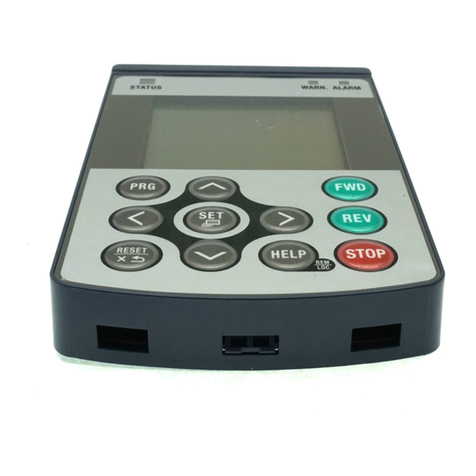
The enhanced keypad is available as a hand-held or remote door mounted
installation for use with the RSi SX drive. It offers a significantly different look
and feel for programming. It also allows you to monitor important parameters.
Figure 1 shows the enhanced keypad.
Keys on the Enhanced Keypad
1.2 Keys on the Enhanced Keypad
Table 1 on page 3 describes the functions of the keys found on the enhanced
keypad when the keypad is the active control source.
2
1 - INTRODUCTION
POWER WARNING FAULT
MENU
1
7
4
REV
2
8
·
5
FWD
3
9
ESC
6
STOP
SHIFT
ENT
MON
F1
OPR
F2
PAR
F3
DIR
F4
0
BENSHAW
ADVANCED CONTROLS & DRIVES
Figure 1: The Enhanced Keypad

3
1 - INTRODUCTION
Key Description
This key performs two functions:
•When pressed by itself, it acts as the F1 function key, the function of which is defined by
parameter F1 Key Config (see RSi SX Parameter Configuration manual).
•When SHIFT is pressed at the same time as this key, the keypad enters Monitor Mode
(see page 7 for more information on this mode).
This key performs two functions:
•When pressed by itself, it acts as the F2 function key, the function of which is defined by
parameter F2 Key Config (see RSi SX Parameter Configuration manual).
•When SHIFT is pressed at the same time as this key, the keypad enters Operate Mode
(see page 6 for more information on this mode).
This key performs two functions:
•When pressed by itself, it acts as the F3 function key, the function of which is defined by
parameter F3 Key Config (see RSi SX Parameter Configuration manual).
•When SHIFT is pressed at the same time as this key, the keypad enters Parameter Mode
(see page 8 for more information on this mode).
This key performs two functions:
•When pressed by itself, it acts as the F4 function key, the function of which is defined by
parameter F4 Key Config (see RSi SX Parameter Configuration manual).
•When SHIFT is pressed at the same time as this key, the keypad enters Direct Parameter
Access Mode (see page 10 for more information on this mode).
When the keypad is in the Direct Parameter Access Mode, the numeric keypad allows you to
set the value of a parameter by keying in the value rather than by scrolling to the desired
value.
The function of this key, the up arrow key, is dependent on the mode of the keypad:
•In modes other than programming, the up arrow key moves the arrowhead from one menu
selection to the next selection.
•When programming the value of a parameter, it increases the value of the parameter. If the
key is held down, the rate of scrolling will increase. The rate of scrolling will increase still
further if the SHIFT key is pressed along with the up arrow key
The function of this key, the down arrow key, is dependent on the mode of the keypad:
•In modes other than programming, the down arrow key moves the arrowhead from one
menu selection to the previous selection.
•When programming the value of a parameter, it decreases the value of the parameter. If
the key is held down, the rate of scrolling will increase. The rate of scrolling will increase
still further if the SHIFT key is pressed along with the down arrow key.
The ESC key is used to discard any changes made and move up one level.
The ENT key is used to save the new value of a parameter. After saving the new value, the
display moves up one level.
This key causes the Menu Display to be shown, from which other keypad modes may be
selected. See page 11 for more information.
The REV key, if enabled by parameter Reverse Mode (see RSi SX Parameter Configuration
manual), commands the motor to begin running in the Reverse direction.
Table 1: Functions of the Keys on the Enhanced Keypad
ESC
MENU
MON
F1
OPR
F2
PAR
F3
DIR
F4
ENT
REV

LEDs On the Enhanced Keypad
1.3 LEDs on the Enhanced Keypad
The enhanced keypad features three LEDs to provide status information. The
following table describes these three LEDs.
4
1 - INTRODUCTION
Key Description
The FWD key commands the motor to begin running in the Forward direction.
The STOP key, if enabled by parameter Stop Key (see RSi SX Parameter Configuration
manual), commands the motor to stop using the type of stop configured by parameter Stop
Mode (see RSi SX Parameter Configuration manual) and using the active deceleration ramp.
If a fault occurs, the STOP key resets the fault.
Table 1: Functions of the Keys on the Enhanced Keypad
FWD
LED Name Duration Operating Condition
POWER Continuous The drive is powered-up.
WARNING Continuous
Abnormal operation is detected, but the abnormality is
greater than a warning. The drive will halt operation
when a fault is detected.
FAULT Continuous
Abnormal operation is detected, but the abnormality is
greater than a warning. The drive will halt operation
when a fault is detected.
Table 2: LEDs on the Enhanced Keypad
STOP

Alpha - Numeric Display
1.4 Alpha-Numeric Display
The enhanced keypad provides a 4 line by 16 character display (twice as large as
that found on the standard keypad), three LEDs for status information, a 0 – 9
numeric keypad (with decimal), and several function keys that are used for
navigation and control. The following sections describe the keys found on the
enhanced keypad and explain how to navigate to various displays.
The following figures are examples of what is shown in the display window of the
Enhanced Keypad during Monitor (MON), Parameter (PAR), Operate (OPR),
and Direct Parameter Access (DIR) modes.
READY T/T
S 46.00Hz +0%
Figure 2
Operate Mode
5
1 - INTRODUCTION
Drive Load
+0%
RDY 110.00Hz K/K
Figure 3
Monitor Mode
Maximum Freq
0303 120Hz
Enter # or
0 320
Figure 4
Parameter Mode
Direct Params
Param Number?
XXXX
RDY 30.00Hz LOC
Figure 5
Direct Parameter Access
Fault Hist #1
Motor Overload
F20
RDY 10.00Hz KYP
Figure 6
Fault History Mode
Active Fault #3
Overcurrent
F8
FLT 10.00Hz KYP
Figure 7
Active Fault Mode

Modes and Displays of The Enhanced Keypad
1.5 Modes and Displays of the Enhanced Keypad
The enhanced keypad provides a variety of modes to assist you in monitoring and
controlling a drive. The principal modes of the enhanced keypad are as follows:
•The Operate Mode
•The Monitor Mode
•The Parameter Mode
•The Direct Parameter Access Mode
•The Menu Display Model
This section describes each of the modes and the displays that are shown for each.
Note, that while each display is specifically tailored to the mode in which it's
shown, the fourth line of the display is common to all modes except the Operate
Mode. The fourth line shows status information (drive status, output frequency,
and active control source). Figure 8 on page 7 shows the fourth line of the display
with the various codes that may be shown and their description.
The Operate Mode
The Operate Mode is the primary mode of the enhanced keypad. The keypad
automatically enters this mode after power-up and a short delay. In this mode,
operational information about the drive is displayed. From this mode, you may
branch to other modes either via the Menu Display Mode or by pressing one of
the navigation keys on the keypad. To return to this mode from other modes,
press SHIFT+OPR/F2.
Figure 9 on page 8 shows a sample display of the Operate Mode with the various
codes that may be displayed and their description.
6
1 - INTRODUCTION

The Monitor Mode
In Monitor Mode, you may observe the value of selected parameters while the
drive is running. This mode is activated by pressing SHIFT+MON/F1, or by
navigating to this mode from the Menu Display Model.
The parameters that may be monitored are as follows:
7
1 - INTRODUCTION
•Output Freq
•Output Current
•Drive Temp
•Out Torq%
•Active Spd Ref
•Drive Load
•Motor Temp
•Out Power
•Motor RPM
•DC Bus Voltage
FLTED
NOEN
NRDY
RDY
OVRV
LO_V
CLIM
TLIM
HICR
HITP
JOG
ZSPD
ACCL
DECL
FWD
REV
DCI
KSTP
LSL
COF
MLOS
Drive is faulted.
No drive enable at the terminal strip.
Drive is not ready (drive enable active).
Drive is ready (drive enable active).
An overvoltage condition exists.
An undervoltage condition exists.
Drive is in Current limit.
Drive is in Torque Limit.
A high current condition exists.
A high temperature warning.
Jog is in jogging mode.
Zero speed; Run command present, but not reference.
Drive is accelerating.
Drive is decelerating.
Drive running in Forward at speed.
Drive running in Reverse at speed.
DC injection braking is active.
Drive stopped from the keypad when terminal strip control source.
Line-start lockout.
Catch-on-the-fly start in progress.
Line power has been interrupted to control.
Status of the Drive
Listed in order from highest to lowest priority; if more than one status is active, the
high-priority status is displayed.
Output
Frequency
keypad display window
RDY 10.00Hz KYP
First line
Second line
Third Line
KST
KYP
LOC
REM
SLC
SLP
TRM
TSK
Keypad speed control with terminal strip Start/Stop control.
Keypad (if Local/Remote switching not enabled).
Local Mode.
Remote Mode.
Serial Link is in complete control.
Serial link is in partial control ( reference from serial link).
Terminal strip ( if Local/Remote switching not enabled).
Terminal strip speed control with keypad Start/Stop.
3-Letter Code for Control Path
Figure 8: Common Status Line for Displays in all Modes Except the Operate Mode

When this mode is first entered, the current value of parameter Output Freq will
be shown. To view the other parameter values, use the down arrow key to scroll
through the parameters. (Of course, you may use the up arrow key to return to a
parameter shown earlier.)
The Parameter Mode
In the Parameter Mode, you may configure the value of a parameter by scrolling.
This manner of configuration is similar to that with the standard keypad. You
may access this mode by pressing SHIFT+PAR/F3 or by selecting “Parameter
Mode” from the Menu Display Mode. Note that if no keys are pressed for 10
minutes while this mode is active, the drive will automatically revert to the
Operate mode.
8
1 - INTRODUCTION
Shown only if keypad
is the control source
(blank otherwise)
keypad display
window
Output Load
FRunning Forward.
RRunning Reverse.
SDrive is stopped.
-Ref. Freq. being set.
Mode
Output
Frequency
KST
KYP
LOC
REM
SLC
SLP
TRM
TSK
Keypad speed control with terminal strip Start/Stop control.
Keypad (if Local/Remote switching not enabled).
Local Mode.
Remote Mode.
Serial Link is in complete control.
Serial link is in partial control ( reference from serial link).
Terminal strip ( if Local/Remote switching not enabled).
Terminal strip speed control with keypad Start/Stop.
3-Letter Code for Control Path
FLTED
NO DRV EN
NOT READY
READY
OVERVOLTAGE
UNDERVOLTAGE
CURRENT LIM
TORQUE LIM
HI CURRENT
HI TEMP
JOG
ZERO SPEED
ACCELERATE
DECELERATE
FORWARD
REVERSE
DC INJECT
KPAD STOP
LS LOCKOUT
SPIN TEST
MAINS LOSS
Drive is faulted.
No drive enable at the terminal strip.
Drive is not ready (drive enable active).
Drive is ready.
An overvoltage condition exists.
An undervoltage condition exists.
Drive is in Current limit.
Drive is in Torque Limit.
A high current condition exists.
A high temperature warning.
Jog is in jogging mode.
Zero speed; Run command present, but not reference.
Drive is accelerating.
Drive is decelerating.
Drive running in Forward at speed.
Drive running in Reverse at speed.
DC injection braking is active.
Drive stopped from the keypad.
Line-start lockout.
Spinning motor start in progress.
Line power has been interrupted to control.
Status of the Drive
Listed in order from highest to lowest priority; if more than one status is active, the
high-priority status is displayed.
Figure 9: Enhanced Keypad Display and Information Shown for the Operate Mode
LOC FORWARD
F 20.00Hz +2%
Enter # or
~

To configure the value of a parameter in this mode, follow these steps:
1. When the Parameter Mode is first entered after power-up, the parameter
groups will be listed in the order shown in the RSi SX Parameter
Configuration manual starting with the first group, Security. On
subsequent entries to this mode, the parameter groups will appear in the
same order but will start with the last parameter group accessed.
2. Use the down arrow key to move the cursor down the list until the
desired parameter group is reached.
3. Press ENT.
4. The parameters in the selected parameter group will now be displayed
starting with the first parameter in the group. Use the down arrow key to
scroll to the desired parameter.
5. Press ENT.
6. The value of the parameter will now be shown on the second line of the
display. Note that this value may be an actual number (such as 120Hz) or
a function (such as 2-wire). If the value is an actual number, the fourth
line will show the range for the parameter. If the value is a function, a
range is not provided. Typical displays for parameter values are shown
below:
9
1 - INTRODUCTION
Maximum Freq
0303 120Hz
Enter # or
0 320
2-wire/3-wire
0401 1
3-wire
2-wire
Name of Parameter
Parameter
Range
Parameter
Address
Current
Value
Sample display for
parameters assigned a value
Sample display for
parameters assigned a function
List of
Available Functions
Parameter
Address
Curren
t
Value
Figure 10: Enhanced Keypad Display of the Two Types of Parameters

7. Change the displayed value to the desired value. For parameters that
configure a function, use the up or down arrow key to move the cursor to
the desired function and then press ENT. Note that the second line does not
show the function just configured; instead it shows a number
corresponding to its position in the function list (with 0 being the first
function listed). For example, in Figure 10 on page 9, the number 1 for the
current value indicates that 2-wire is selected, not 3-wire.
For parameters that are assigned a value, you may also scroll to the desired
value by using the up and/or down arrow keys and then pressing ENT to
store the new value. Alternately, you could use the numeric keypad to type
the parameter’s value.
With either type of values, if you change your mind and do not wish to save
the selected value (and you have not yet pressed ENT), press ESC to abort
and return to the display showing the parameters in the parameter group.
8. After configuring the value of the parameter, the list of parameters will
return to the display. You may now select another parameter from the same
group to configure, or press ESC to return to the list of parameter groups.
To return to the Operate Mode, press SHIFT+OPR/F2 (or navigate to it via
the Menu Display mode).
The Direct Parameter Access Mode
In the Direct Parameter Access Mode, you may navigate directly to a parameter
by entering the parameter’s address. (Parameter addresses are shown in the
Parameter Configuration manual.) You access this mode by pressing
SHIFT+DIR/F4 or by selecting “Direct Params” from the Menu Display Mode.
Once this mode is active, you may enter a new value for the parameter by keying
in the value on the numeric keypad (rather than scrolling to the desired value).
To configure the value of a parameter in this mode, follow these steps:
1. When the Direct Parameter Access Mode is entered, the display will ask
you for the address of the desired parameter number as shown below:
2. Obtain the parameter address from the Parameter Configuration Manual
and type the address. As you type the address, it will appear on the third line
of the display.
3. Press ENT.
4. The parameter will be displayed and will show its current value. Note that this
value may be an actual number (such as 120Hz) or a function (such as 2-wire).
If the value is an actual number, the fourth line will show the range for the
parameter. If the value is a function, a range is not provided. Typical displays
for these two types of parameter values are shown in Figure 10, page 9.
10
1 - INTRODUCTION
Direct Params
Param Number?
XXXX
RDY 30.00Hz LOC

5. Change the displayed value to the desired value. For parameters that
configure a function, use the up or down arrow key to move the cursor to
the desired function and then press ENT. Note that the second line does not
show the function just configured; instead it shows a number
corresponding to its position in the function list (with 0 being the first
function listed).
For parameters that are assigned a value, use the numeric keypad to key in
the parameter’s value. (Alternately, you may scroll to the desired value by
using the up or down arrow keys.)
6. Press ENT to save the new value. (If you do not wish to save the selected
value , press ESC to abort and return to the display showing the parameters
in the parameter group.)
7. After configuring the value of the parameter, the list of parameters will
return to the display. You may now select another parameter to configure,
or press ESC to return to the list of parameter groups. To return to the
Operate Mode, press SHIFT+OPR/F2 (or navigate to it via the Menu
Display mode).
The Menu Display Mode
The Menu Display Mode may be thought of as the hub on which all the other
modes are mounted. Once you navigate to this mode by pressing the MENU key
on the keypad, you may highlight the desired mode (by pressing the up or down
arrow key) and then pressing the ENT key. The selected mode will then become
active, and the display for the mode will be shown on the keypad.
The Active Faults Mode
When a fault occurs, the Active Faults mode automatically activates. The display
for Active Faults shows the phrase “Active Fault” followed by a sequential
number. The second line shows the description of the fault, while line three
shows the fault code number. (See RSi SX Parameter Configuration manual for a
list of fault descriptions and codes, as well as suggestions for recovering from the
fault condition.) A typical display would appear as follows:
To recover from a fault, correct the condition causing the fault and then press
STOP.
11
1 - INTRODUCTION
Active Fault #3
Overcurrent
F8
FLT 10.00Hz KYP

The Fault History Mode
The enhanced keypad stores the four most-recent faults, and these are viewed in
the Fault History mode. This mode is accessed by navigating to the Menu Display
Mode and then selecting Fault History.
The display for Fault History shows the phrase “Fault Hist” followed by a
sequential number, with number 1 indicating the most-recent fault. The second
line shows the description of the fault, while line three shows the fault code
number. A typical display would appear as follows:
Upload/Download Mode
For MCP software revisions of 3.71 or greater and enhanced keypads with
software revision 4.00 or greater, an enhanced keypad (EKP) may be used to
store a complete parameter set from an RSi SX drive. This becomes particularly
useful when using an enhanced keypad as a hand-held controller/programmer.
To use this facility, the customer’s parameter set must first be stored in the RSi
SX via parameter AFN 90 (Param STO/RCL). The customer set of parameters
may then be uploaded to the EKP for transport to another SX drive.
To upload the parameter set, perform the following steps:
•On the EKP, press the MENU button.
•Use the cursor to navigate to the keypad setup screen.
•Press ENT.
•Highlight the option entitled “UPLoad EEPROM,” which is the upload
parameter.
•Press the ENT key twice to execute the upload operation. During the
transfer, the display looks like this: DRV>>>>EKP
When the upload completes successfully, line 3 of the keypad will show
“STORED” and line 4 will provide a Benshaw application number such as
“b01V124". If the upload is not successful, the display will indicate “Flash
Prog Error.”
You may now connect the EKP to the RSi SX drive to which the parameter
set will be downloaded. To avoid possible errors, the APPL Sw Version of
the unit to which the parameters will be downloaded should match that of
the unit from which the parameters were uploaded.
12
1 - INTRODUCTION
Fault Hist #1
Motor Overload
F20
RDY 10.00Hz KYP

To download the parameter set, perform the following steps:
•On the EKP, press the MENU button.
•Use the cursor to navigate to the keypad setup screen.
•Press ENT.
•Highlight the option entitled “DNload EEPROM,” which is the download
parameter.
•Press the ENT key twice to execute the download operation. When the
download operation starts, the display will show the following information:
The model number of the source drive — for example, RSi050SX4B;
The MCP code revision of the source drive — for example, MCP3.90; and
The application number being transferred — for example, b01V124.
During the download operation, the display will indicate:
EKP>>>>DRV
•Once the download operation is complete, activate the downloaded
parameter set in the destination drive by loading it from the stored customer
set. To accomplish this, navigate to parameter AFN 90 (Param STO/RCL)
and select “Load Param.” The downloaded parameter will then become the
active parameter set.
zNote:
Some model specific adjustments may be required if the model number of the
source and destination drives are not identical.
13
1 - INTRODUCTION

Notes:
14
1 - INTRODUCTION

2 Installation
15

Inspection Upon Receipt
2.1 Inspection Upon Receipt
When you first receive the EKP (enhanced keypad), perform the following
checks:
•Verify that you have received the proper keypad by checking the carton
label and other shipping documentation.
•Carefully inspect the package for any damage sustained in transit. If damage
is apparent, the shipping agent should be notified.
Components Of Installation Kit
2.2 Components of Installation Kit
After checking that the correct keypad arrived in good condition, verify that all
components for installing the keypad are included. The following components
should be in the kit:
•1 Remote Keypad Unit (RSiEKPG-01).
•1 six-foot interconnection cable (RSiEKPCABLER6).
•1 hardware package (two threaded studs, two oversized washers, and two
locking nuts).
If there are missing parts, please notify your nearest Benshaw representative.
16
2 - INSTALLATION

Instructions For Panel-Mounting
2.3 Instructions for Panel-Mounting
If the enhanced keypad is to be hand-held, you only need to connect it to the drive
by using the included interconnection cable. See 2.4 on page 18 for more
information.
To mount the enhanced keypad on the front of the host enclosure, perform the
following steps:
1. Disconnect all power to the drive.
2. Drill mounting holes in the host enclosure using the drilling template
shown in Figure 12 on page 19.
3. Insert a threaded stud into each of the threaded inserts on the reverse side
of the enhanced keypad and tighten finger-tight.
4. Place the enhanced keypad on the enclosure so that the threaded studs slide
through the mounting holes drilled into the enclosure. Hold the keypad in
place so it does not fall while performing the next two steps.
5. Slide an oversized washer onto each of the threaded studs.
6. Screw a locknut on to each threaded stud and tighten with a torque wrench
to 26 in-lb of torque. It is very important to tighten the nuts securely to
preserve the environmental integrity of the host enclosure.
7. Restore power to the drive.
8. The enhanced keypad is now mounted. See the following section for
connecting the keypad to the drive.
17
2 - INSTALLATION

Connecting The Keypad To The RSi SX Drive
2.4 Connecting the Keypad to the RSi SX Drive
The enhanced keypad is connected to the RSi SX drive with the six-foot
interconnection cable (part number RSiEKPCABLE6). This cable has RJ45
connectors on each end. (If you require a longer cable, Figure 11 provides the
pin-out information to construct a custom cable.)
Plug one end of the cable into the port on the enhanced keypad. (For
panel-mounted keypads, the port should be accessible through the larger, center
hole drilled in the enclosure.)
Plug the other end into the port found on the RSi SX control board just above the
TB4 terminal group. (See RSi SX Parameter Configuration manuals for further
information.)
Enabling Start/Stop & Reference Control
2.5 Enabling Start/Stop & Reference Control
Enter the direct parameter mode as described on page 10. Select parameter 875.
The valid settings are:
SKP - Drive can be monitored and stopped from the enhanced keypad. No start or
reference control.
Both - The standard keypad and the enhanced keypad may be used to start/stop
the drive and change the reference frequency. If communication is lost with
either keypad, the drive will stop and fault.
Both NoFlt - Same as "Both", but if communication is lost with either keypad, a
fault will not be generated.
zNote: Please see the RSi SX Parameter Configuration manual for details on
the configuration of the control and reference pathways.
18
2 - INSTALLATION
12
34
56
78
12345678
Plug (male) Jack (female)
S
traight-thru
Connection
Pin 1: +24 Vdc
Pin 3: SIO+
Pin 6: SIO-
Pin 8: Common
Figure 11: Pin Connection for RJ45 Connection
Table of contents
Other BENSHAW Keypad manuals
