BENSON BENDX ACHW 34 User manual

AIR CONDITIONER WATER HEATER
OPERATION MANUAL

CONTENTS
PAGE
1. 1
3. 5
4. 9
5. 11
6. 31
2. 3
7. 91
8. 21
Note:Installation and maintenance are to be performed only by qualified personnel who are familiar
with local codes and regulations,
Caution:Sharp edges and coil surfaces are a potential injury hazard.Avoid contact with them.
Warning:Moving machinery and electrical power hazard.May cause severe personal injury or death
.
Disconnect and lock off power before servicing equipment.
SPECIAL FEATURES
OUTLINES AND DIMENSIONS
WIRING DIAGRAMS
SAFETY PRECAUTIONS BEFORE INSTALLATION
INSTALLATION
REMOTE CONTROLOPERATION GUIDE
SERVICING AND MAINTENANCE
TROUBLESHOOTING
9. 23
INSTALLATION INSTRUCTIONS FOR R290
10. 25
TANK INSTALLATION AND AIR BLEEDING OF SYSTEM
11. 26
SYSTEM INSTALLATION
12. 27
EQUIPMENT DESIGN SAFETIES,OPERATION SET POINTS AND GENERAL DESIGN
13. 28
WATER SOFTNESS OR HARDNESS
14. 29
EXCLUSIONS TO WARRANTY
15. 30
HEAT EXCHANGER AND LEAKS ON THE TOP WATER SECTION

1. SPECIAL FEATURES
HEAT RECLAIM EQUIPMENT (OUTDOOR UNIT)
ONEOFTHE MOST ENERGY EFFICIENT HEATING SYSTEM IN THE MARKET
ACHWheat reclaim series is absolutely free from electricaleliments.The design utilizes the otherwise
wasted condenser heat from air-conditioner system to generate domestic hot water at temperature of
up to 60℃.Cogenerationeffect.
EFFICIENCY COMBINED WITH SAFETY
Unlike the conventional heat reclaim system which with refrigerant pipe submerge into water tank,
ACHWincorporate high efficiencyTwin copper tubeheatexchangerthatcirculatesthe
the waterinandoutofthe tank.This unique safety feature renders itpracticallyimpossible for the
refrigeranttoenter the water circuit.
GREAT SAVINGS ON ELECTRICITY
CombiningtheAirconditionerandhotwatersystemsavesyouelectricity for water heating.
ACHWheat reclaim unit reduces the condensing load of split unit air-conditioner thus reduces the
power consumption.
ROTARY COMPRESSOR
-The ever popular rotary compressor is more energy efficient and has a higher output to weight ratio.
1

INDOOR UNIT
EASY INSTALLATION
-The wall mounted fan coil unit is easily installed because of its compact size,slimness and light
weight.
-Slim and short outdoor unit can be easily installed even inanarrow wallareas.
QUIETOPERATION
-Cooling comfort is improved by whisper-quiet operation which is achieved by a tangential fan.
EXCELLENT AIR DISTRIBUTION
-Air discharge direction can be adjusted in four directions, manually or automatically by using LCD
remote control,coupled with good air flow,the unit provides excellent air distribution.(notallmodels)
FACILITATED MAINTENANCE ENSURED
-The new designfilter is slide-out type which can be easily removed at the air inlet grille for
cleaning.
WIRELESS REMOTE CONTROL
-The compact LCD transmitter is able to operate the air conditioner unit within the distance of 9
meters.
-Fan motor speed can be set at low/medium/high or automatic.
-Sleep mode automatically increase set temperature since room temperature is lower at night thus
achieving comfort surrounding.(EconomyMode)Displaylightingdims
-Air flow direction can be controlled automatically.
-Room temperature is controlled by electronic thermostat.
-The unit can be preset to on and off automatically for maximum of 15 hours by using timer on/off.
SLIT FIN
-The unique Hydrophilic slit fin has greatly improved the air flow and the contact surfaces with the
air thus to boost the cooling capacity.
2

2.Remote Controller Operation Guide
Remote Controller
1
Transmission source
The source where the signal will
be transmitted
2
On/Off Button
- Press once to start the air conditioner
- Press again to stop the unit.
7
Fan speed selection
- Press the button until the desired fan
speed is achieved.
5
Operation mode
- Press the MODE button to select the
- For cooling only unit ,the available
modes are:COOL,DRY&FAN.
type of operating mode.
9
Sleep mode setting
- Press the button to activate sleep
- When it is activated in COOL / HEAT
mode. the set temperature will be
increased /decreased 2 after 2
hours.EconomycycleLedDimmer
mode.This function is available under
COOL & AUTO mode.
4
Temperature setting
O perat ion dis play
-To set the desined room temperature,
press the button to increase or
decrease the set temperature.
-The temperature setting range is 16~
31 .
CSummerandwinter24`C
C
11 On timer setting
- Press the button to activate the on
- Press the button again to release
timer.
timer function .
13
Hour setting button and
Minite setting button
14
Clock time setting
- Press HR and MIN button to set timer
- Press the button to set timer
to realtime.
15
Reset button
- Press the button to activate the off
- Press the button again to release
timer.
timer function .
3
6
Hot water button
- Press the button to select or stop
water heating mode .See"Manual"
- Press the button to activeate the
automatic air swing function .
- Press the button to distribute the air
to a specilic direction .
8
Air-blowing angle adjusting
button
10
Automatic air swing
12
OFF timer setting
3

4
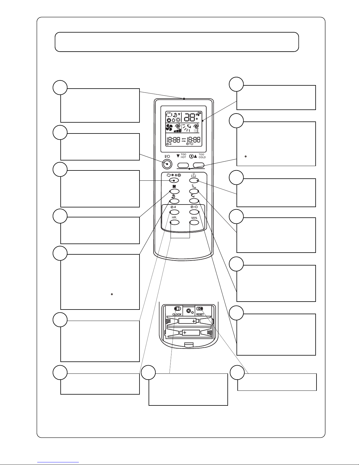
Special Opera ons of the AC Hot Water
Dry Mode Removes moisture from the air in high humidity by cycling the indoor
fan offor to very low speed.
Cooling Only Use the system the same as you would use any air condi oning system,
set you air movement flaps to suit the room. Recommended
temperature to be set to is 24`C, however every 1`C increase may save
as much as 10% on your running costs.
ng only Use the system the same as you would use any air condi oning system,
set you air movement flaps to suit the room. Recommended
temperature to be set to is 22`C, however every 1`C decrease may save
as much as 10% on your running costs.
Auto This will select a temperature displayed on the screen in the centre of
the unit and maintain it in h ng or cooling. (not a recommended
ng)
Hot Water Only The system can be manually switched on now, Via a wall switch or a
clock and smart systems to gain advantage of off peak power. The
infra red controller can also switch the system on. The water is
automa cally controlled to a set temperature of 60`C.
Cooling and Hot Water You operate your system as a normal air condi oner and while you are
doing so it he ng your hot water for Free.
ng and Hot Water Because of the unique design of the system, the indoor unit will only
start to func on when the tank temperature is above 32`C. If hea ng is
required straight away then turn offyour hot water(remember to turn
back on later, or switch the system to hot water only l it reaches
32`C and then turn the he g on as well.
Auto and Hot Water Same as Cooling and ng modes
Dry and Hot Water Func on not available. Hot Water is not produced in the func on as the
op on of the system is not conducive to produce hot water.
Smart System The Hot Water Smart System will monitor if the compressors opera on
in Auto, Cooling and Hea ng, if the compressor does not operate for
One hour, the system will switch to Heat Pump hot water mode. The
Smart System was designed if you accidentally forget to turn offyour
aircondi oner and the house/room has cooled down over night and you
or your family shower in the morning, the hot water system would have
started to heat the water because of the Smart System.
The compressor needs to run to generates all the heat that heats your
families water.

3. OUTLINES AND DIMENSIONS
BENDX ACHW 34
BENDX ACHW 34
5

3. OUTLINES AND DIMENSIONS
BENDX ACHW 41
BENDX ACHW 51
BENDX ACHW 41
BENDX ACHW 51
6

3. OUTLINES AND DIMENSIONS
BENDX ACHW 65
BENDX ACHW 65
7

WATER TANK
8
This tank is a guide only for connection, installation may vary with tanks supplied.
Specifications subject to change for product improvements.
!
650kPa P and T
Valve Be fitted
(Recommended filter
or strainer)

4.WIRING DIAGRAMS
INDOOR UNIT
OUTDOOR UNIT
Model 34,41 and 51
Model 34,41 and 51
9

4.WIRING DIAGRAMS
INDOOR UNIT
OUTDOOR UNIT
Model 65
Model 65
10

5. SAFETY PRECAUTIONS BEFORE INSTALLATION
Before operating, please read the following〝Safety Precautlons〞carefully.
To prevent injury to the user or other people and properties damage,the following instructions must be
followed.
·Incorrect operation due to ignoring of instruction will cause harm or damage,the seriousness is
classified by the following indications.
!Warning:This sign indicates the possibility of causing death or serious injury.
Caution:This sign indicates the possibility of causing injury or damage to properties only.
Warning
·This unit must be installed by a qualified technician.
·All field wiring must accordance to the National Wiring Regulation.
Important
The wires in this mains lead are coloured in accordance with the following code:
Green-and-yellow Earth
Blue
Brown Live
Neutral
→
→
→
As the colours of the wires in the mains lead of this appliance may not correspond with the coloured
markings identifying the terminals in your plug,proceed as follows:
·The wire which is coloured green-and-yellow must be connected to the terminal in the plug which is
marked with the earth symbol or coloured green or green- and- yellow.
·The wire which is coloured blue must be connected to the terminal which is marked with the letter N or
coloured black.
·The wire which is coloured brown must be connected to the terminal which is marked with letter L or
coloured red.
Note
If the supply cord is damaged,it must be replaced by the special cord obtainable at authorized
service/parts centers.
This unit is not provided with a plug,therefore the power supply wire must be connected by a qualified
Electrician.
Caution
Remove power plug or disconnect from the mains before servicing the appliance.
11
!
!

Symbol (with white background) denotes item that is PROHIBITED from doing.
Symbol (with black background) denotes item that is COMPULSORY to be carried out.
Caution
Please confirm the following important points when installation
·Grounding is necessary
It may cause electrical shock if grounding is not perfect.
·Do not install the unit where leakage of flammable gas may occur
In case of gas leaks and accumulates at the surrounding of the unit,it may
cause fire ignition.
·Confirm drainage piping is connected properly
If it is not connected perfectly,it may cause water leakag,thisistheinstallers
Liabilityandshouldbecheckedatcommisioning
.·Confirm the unit is switched off before install,service or maintain the unit
If it is not switched off, it may cause injury to the installer by electricalshock
orany of themoving part especially fan.
·Do not overcharge the unit
Chargeasperchargingchartsgiven.Over charge will cause over current or
damage to the compressor.UnitsarenotPrecharged.
·Confirm cover back the unit panel after servicing or installation
Unsecure panel will cause unit noisy.
!
!
!
!
!
12

6.INSTALATION
13
Cycle Water Inlet
Cold Water Inlet
Cycle Water Outlet
Pressure Regulator
Valve is required
(500kPa)
Mixing Valve
V 50 C

MINTENANCE&SERVICING SPACE
AIR FLOW DIRECTION
CAUTION: Do not install unit near the door way
beacause excessive fresh air cause
panel condensation on the unit.
Fig. 1
(A) INDOOR UNIT
Install the fan coil (indoor) unit at a location with following requirements
•Location is suitable of wiring,piping and drainage.
•No obstruction of air flow into and out of unit where cooler air can be evenly distributed.(See fig.1)
•Ensure that air discharge is not short circuited with air intake.
•Ensure that wall is sufficiently strong、rigid、flat,perpendicular and vibration free.
•Where air filter can be slided in or out easily
•Where there is not danger of flammable gases(tocloseotherGasappliances)
•Where maintenancecanbecarriedouteazierly(suggestedOneMeterabovegroundlevel).
•Also to take into consideration a place for the installation of the HotWaterSystemManualswitch
ifitisrequired.
1) SELECTION OF LOCATION AND SPACE
14

(B)OUTDOOR UNIT
As condensing temperature rises,evaporating temperature rises and cooling capactlydrops.In order
to achieve maximum cooling capacity,the location selected for outdoor unit should fulfill the following
requirements:
•Install the condensing (outdoor)unit in away such that hot air distributed by the outdoor condensing
unit cannot be drawn in again (as in the case of short circuit of hot discharge air).Allow sufficient
space for maintenance around the unit.
•Ensure that there is no obstruction of air flow into or out of the unit.Remove obstacles which block
air intake or discharge.
•The location must be well ventilated,so that the unit can draw in and distribute plenty of air thus
lowering the condensing temperature.
•A place capable of bearing the weight of the outdoor unit and isolating noise and vibration.
•A place protected from direct sunlight highrisebuildingsandambientsabove48`C.Otherwise
use an awning for protection,if necessary(300mmclearncerequiredabovetheunit).
15
INSTALLATION CLEARANCE
•Outdoor units must be installed such that there is no short circuit of the hot discharge air or
obstruction to smooth air flow. Werecommendtheunitsbeinstalled0nemeterabovegroundlevel
werepracticable.
CAUTION:If the condensing unit is operated in an atmosphere containing chemicalsnearindustrial
areas,highsalt(coastal area)ornearborewater,such substancesshortenthelifetime
of the unitduetocorrosion.
ALL MODELS
Minimum Distance 1000mm 300mm 300mm 500mm
A
A
B
B
C
C
D
D

16
2)DRILL HOLES AND MOUNTING INSTALLATION PLATE
CAUTION:
i) Please check the unit weight for each model. Always ensure that the wall is sufficiently
strong to withstand the weight. If not,it is necessary to reinforce the wall with plate, beams
or pillars.
ii) The installation plateprovided MUST be used,thismaybemountedonanothermultiply
sheetweretheplatedoesnotpickupenoughfixingpoints.
,•Paste the installation plan provided on the desired location on the wall and mark the holes
location accordingly.
•Ensure that the minimum maintenance and servicing space at the top,left and right side of
the units is reserved.
•Ensure also the levelness of the installation plate12`downtowardsthedrainend.
•Drill the screw mounting holes(minimum 4 screws are required).
•Drill the pipe hole at the location as per plan.(This is only applicable for rear piping outlet
installation).
Note:The hole should be drilled slightly lower at outdoor side as per figure below:
•Fix the installation plate firmly to wall,without tilting to left or right.Use a plumb line,if available.
•Fixing method:

17
3)WIRING
ELECTRICAL CONNECTION
•Wiring regulation on wire diameters differ from country to country. Please refer to your
LOCAL ELECTRICAL CODES for field wiring rules. Be sure that installation comply with
such rules and regulations.
GENERAL PRECAUTIONS
•Ensure that the rated voltage of the unit corresponds to the name plate before carrying
out proper wiring according to the wiring diagram.
•Some units can be plugged into local power supplys. Check with your Electrical contractor.
•The unit must be GROUNDED to prevent possible hazards due to insulation failures.
•All wiring must be firmly connected.
•All wiring must not touch the hot refrigerant piping, compressor or any moving parts of
fan motors.
•The field wires from the indoor unit must be clamped on the wire clamp
.
4)REFRIGETANT PIPING
MODEL
PIPE Φ , D (mm) IMPERIAL DLE RIGED DIE
A (mm)
6.35 (1/4”) 1.3
9.52 (3/8”) 1.6
12.7 (1/2”) 1.9
15.88 (5/8”) 2.2
0.7
1.0
1.3
1.7
INDOOR TO OUTDOOR
DATA
Max.Length,L(m) 10
5
4
Max.Elevation,H(m)
Max.No.of Bends
MAXIMUM PIPE LENGTH AND MAXIMUM NUMBER OF BENDS
PLARE CONNECTION
•Cut the pipe stages by stages,advancing the blade of pipe cutter slowly.
•Remove burr with the burr remover.Hold the flaring end down to prevent burrs
from dropping inside pipe.
•The exact length of pipe protruding from the face of the flare die is derermined
by the flaring tool.The table shows the use of an imperial die and riged die.
Fix the pipe firmly on the flare die. Match the centers of both the flare die and the
flaring punch,and tighten flaring punch fully.

18
Moisture and Air purification
Take off covers for gas and liquid valves betfre staring, put covers back tightly after work. (gas may leak)
Tighten connecting nuts for indoor and outdoor Flares, Small amounts of leakloc can be used as well
Back seat Stop Valves.
Open all Lo handles of mixing valve and evacuate to 500 microns,note R290 connected to Hhandle
evacuate to bottle tap.
Refer to figure at right to connect stop valve, gas charging hose, mixing valve and vacuum pump.
Use vacuum pump
-76cmHg
stop valve
(liquid) auxiliary gas
port
stop valve
(gas)
compound vacuum meter
mixing valve
Hihandle
gas charging hose
vacuum pump
Lohandle
gas charging
hose
Close vacuum pump,open Hhandle to charge the system,rate given.
Check the joints of indoor and outdoor units if there is any gas leakage(with a leak tester or soap water)
Gas
Bottle
This manual suits for next models
3
Table of contents
Popular Air Conditioner manuals by other brands

Friedrich
Friedrich ZoneAire Compact P08SA owner's manual

Frigidaire
Frigidaire FRS09PYW1 installation guide

Panasonic
Panasonic CS-WU12VKYF Series operating instructions

Frigidaire
Frigidaire FFRE0533S1E0 Use & care guide

Sears
Sears Kenmore P/N93SR-D02 owner's manual

Panasonic
Panasonic CS-CZ25WKE Service manual