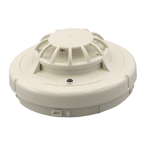
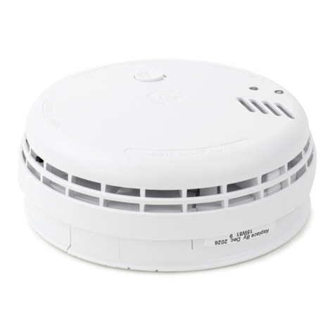
Bentel Security RF 501t User manual

Rivelatore ottico di fumo
RF 501t
Optical smoke detector
N.B. Le informazioni contenute nel presente foglio d’istruzione
sono soggette a modifiche senza preavviso e non rappresentano
un impegno da parte della Bentel s.r.l..
N.B. The information contained herein is subject to change, BEN-
TEL s.r.l. which holds the right to carry out such changes without
notice.
CONFORME ALLA NORMA UNI EN54 parte 7
MEETS STANDARDS EN 54/ 7
CARATTERISTICHE GENERALI
L’RF501t è un rivelatore combinato sensibile sia alla presenza di
fumo sia alle alte temperature.
È quindi possibile rivelare tempestivamente il verificarsi nell’am-
biente in cui esso è installato, di incendi caratterizzati dallo svilup-
po di fumo come nella combustione di legno, cellulosa, stoffa e
materiali simili, mentre negli altri casi l’innalzamento della tempe-
ratura provoca ugualmente la segnalazione di allarme.
FUNZIONAMENTO
Sono racchiusi al suo interno, in una apposita camera di raccolta
del fumo, un emettitore ed un ricevitore di luce all’infrarosso.
In condizioni normali, cioè in assenza di fumo, il ricevitore vede
solo una piccola parte della luce proveniente dall’emettitore, even-
tuale fumo nella camera provoca, contrariamente, un considerevo-
le aumento del segnale ottico ricevuto.
Perchè il rivelatore vada in allarme è necessario che il fumo per-
manga nella camera per un tempo di circa 5 secondi.
Il rivelatore durante il suo funzionamento normale provoca, ad in-
tervalli di circa 25 secondi, una breve accensione del LED di se-
gnalazione allarme per indicare che è correttamente alimentato e
funzionante.
Il rivelatore permette inoltre di provocare artificialmente una condizio-
ne di allarme, a tal fine si dovrà avvicinare alla base del rivelatore in
corrispondenza del LED di allarme una calamita, ad esempio il ma-
gnete di un altoparlante, ed attendere circa 5 secondi perchè il rivela-
tore vada in allarme.
Nel circuito è anche presente un elemento sensibile alle variazioni
di temperatura che fa scattare l’allarme nel caso in cui la tempera-
tura ambiente superi la temperatura di soglia prefissata di 55 °C.
INTERFACCIAMENTO
Nella progettazione di un impianto antincendio è essenziale verifi-
care la compatibilità delle caratteristiche elettriche dei rivelatori
con quelle della centrale di controllo.
GENERAL FEATURES
The RF 501t is a combined detector sensitive to the presence of
both smoke and heat.
It is possible therefore to signal in good time the presence of fire
characterized by the generation of smoke, as in the case of the
combustion of wood, cellulose, fabric and similar materials. The
rise in temperature causes alarm signalling in the case of other
materials. FUNCTION
An infra-red transmitter and infra-red receiver are contained within
the smoke chamber of the device.
In normal conditions, that is, in the absence of smoke the receiver
picks up only a small part of the I.R. radiation coming from the
transmitter, contrarily, the presence of smoke within the chamber
causes a considerable increase in the optical signal received.
It is necessary for smoke to be present in the chamber for 5 se-
conds before alarm is signalled.
During normal function procedure, at 25 second intervals, the
alarm signal LED lights briefly, to indicate the correct functioning
and powering of the circuit.
It is also possible to purposely cause an alarm, this is done by pla-
cing a magnet near the bottom part of the detector in correspon-
dence with the LED, in so doing, after a period of five seconds the
detector signals alarm state.
The circuit also has a heat sensitive element that causes alarm
state if the temperature of the surroundings exceeds the estab-
lished limit of 55 ºC.
INTERFACING
In the planning of a fire-prevention system it is essential to check
the compatibility of the electrical features of the detector with tho-
se of the control system.
CARATTERISTICHE TECNICHE
TECHNICAL FEATURES
Tensione di alimentazione
Supply voltage 24V
(12.6 ÷28 V )
Corrente a riposo
Stand-by current 80 ÷130 µA
Corrente in allarme
Current in alarm state 5 ÷50 mA
Corrente di mantenimento
Minimum current to maintain alarm 5 mA
Uscita per indicatore remoto
Output for remote indicator 100 mA max.
Temperatura di funzionamento
Temperature range 0 ÷50 °C
Dimensioni base
Size of detector base (∅x H) 104 x 22 mm
Dimensioni unità di rivevazione
Size of detector unit (∅x H) 100 x 43 mm
Peso base
Weight of detector base 40 gr.
Peso unità di rivelazione
Weight detector unit 104 gr.
V4.2 BBF501T 4.1 010897

Va verificata, innanzitutto, la tensione di alimentazione della linea che
nella maggior parte delle centrali è di 24 Volt; il rivelatore RF 501t fun-
ziona con tensioni di linea comprese tra 12 e 30 Volt ed ha un consu-
mo a riposo inferiore a 100 µA (24 Volt).
Da verificare, inoltre, la corrente assorbilta dal rivelatore in caso di al-
larme che deve essere compresa tra i limiti imposti dalla centrale.
Da questo punto di vista il rivelatore RF 501t in condizione di allar-
me può essere considerato come una resistenza di 470 ohm con
in serie una caduta di tensione di 3 Volt.
La caratteristica Tensione/Corrente in allarme e mostrata in fig. 3.
COLLEGAMENTI ELETTRICI
In fig. 1 è rappresentato un tipico circuito di zona comprendente 3
rivelatori con linea di collegamento a 2 fili.
Alla fine della linea è presente un diodo od una resistenza di fine
linea (r.f.l.) il cui valore dipende dalla centrale usata.
La lampada di ripetizione (L.R.), collegata al morsetto [R], deve essere
alimentata da una linea di alimentazione separata come si vede in fig. 1.
L’assorbimento di ogni lampada deve essere al massimo di 100 mA.
Nel caso di più rivelatori installati nella medesima stanza, può essere
utile installare una sola lampada remota per il monitoraggio di tutti i ri-
velatori, in questo caso il collegamento va effettuato come in fig. 2.
INSTALLAZIONE
Il rivelatore RF 501t è composto da 2 parti separate: l’unità di rive-
lazione vera e propia e la base (fig. 4).
Effettuati i collegamenti ai 4 contatti a molla posti sulla base essa
va fissata al soffitto per mezzo di 2 viti Fisher.
L’unità di rivelazione viene bloccata avvitandola sulla base in sen-
so antiorario.
Il rivelatore va montato ad almeno 60 cm di distanza da muri o da qua-
lunque altro oggetto che possa bloccare il flusso d’aria verso lo stesso.
Above all it is necessary to verify the voltage of the control panel
line, which in most systems is 24 Volts; the RF 501t functions with
line tensions between 12 and 30 Volts and has a stand-by current
of 100 µA (24 Volts).
It is also necessary to check current absorption on the detector in
the case of alarm, this must be within the limits on the system.
In alarm conditions the RF 501t detector may be considered as a
resistance of 470 ohm with, in series, a drop in tension of 3 Volts.
Shown in fig. 3 is typical of Tension/Current when alarm is verified.
ELECTRICAL CONNECTION
Fig. 1 illustrates a typical zone circuit with 3 detectors with a 2 wire
connecting line.
A diode or a line end resistance (l.e.r.) is present, the value of
which depending on the system in question.
The repeater light (R.L.), connected to clip [R], is to be powered by
a separate line as shown in fig. 2.
The current of each light is to be at the most 100 mA.
When several detectors are to be installed in one room, it may be of
benefit to install only one remote light for the monitoring of all the de-
tectors, in this case the connection is to be carried out as in fig. 2.
INSTALLATION
The RF 501t detector is made up of 2 separate parts: the base
(fig. 4) and the actual detector.
When the 4 spring contacts, situated on the base, are connected,
fit the device to the ceiling by means of two Fisher screws.
Screw the remaining unit onto the base in an anti clockwise manner.
The detector is to be fitted at least 60 cm from surrounding walls or
from any other object that may obstruct the flow of air towards it.
FIG. 1 Collegamento con spia remota distinta.
Connection with separate remote indicator. FIG. 2 Collegamento con spia remota in comune
Connection with the same remote indicator.
FIG. 3 Corrente di allarme in funzione della tensione
Alarm current (I) versus voltage (V). FIG. 4 Base del rivelatore
Detector base.
Other Bentel Security Smoke Alarm manuals
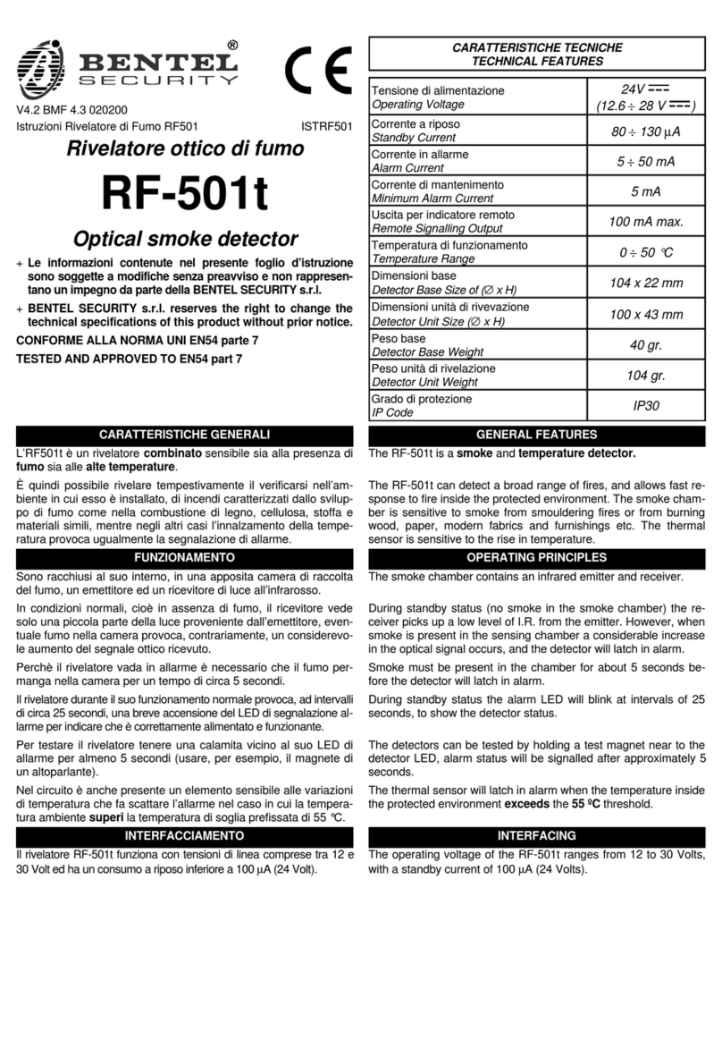
Bentel Security
Bentel Security RF-501t User manual
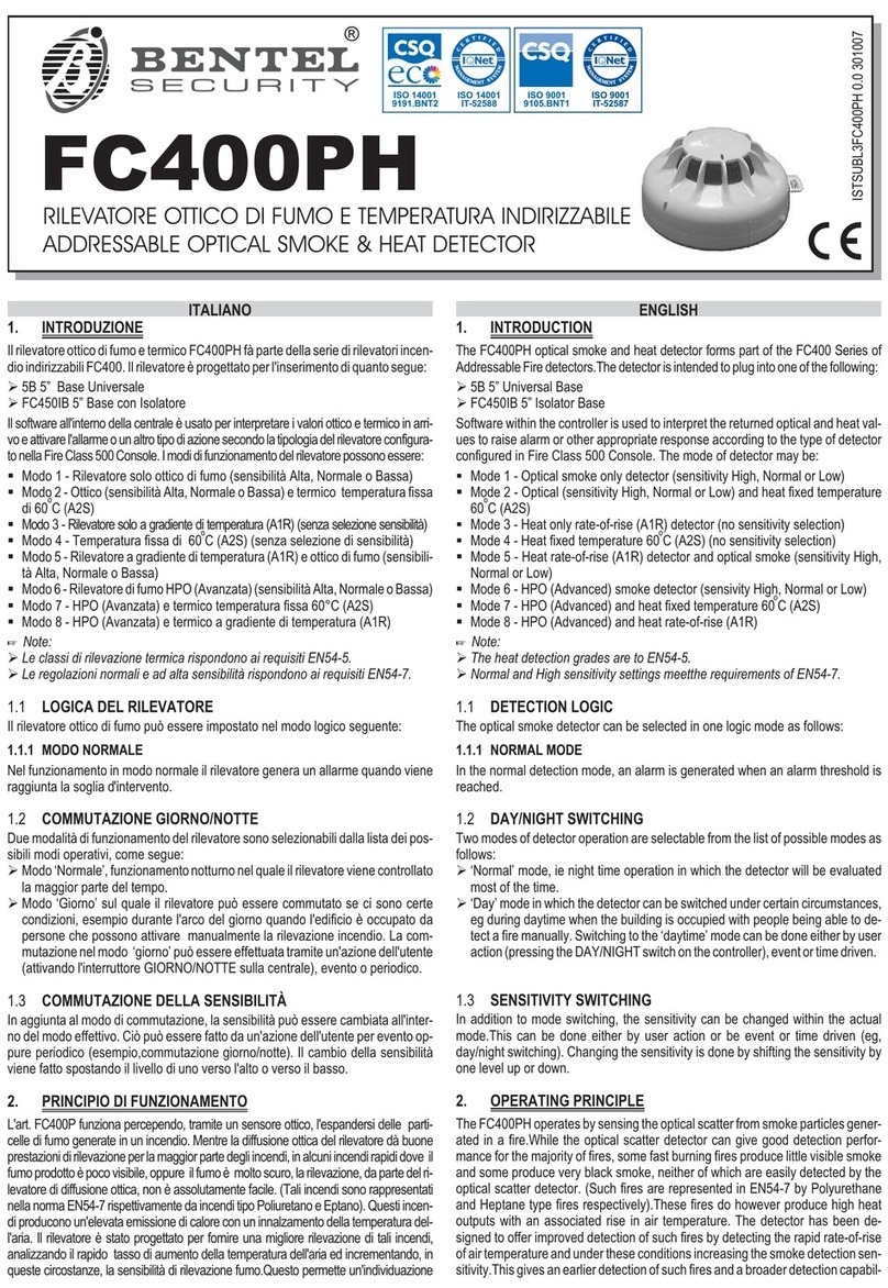
Bentel Security
Bentel Security FC400PH User manual
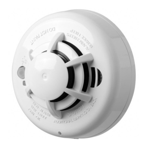
Bentel Security
Bentel Security ASD30 User manual
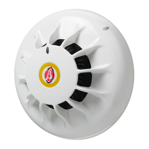
Bentel Security
Bentel Security 601PH User manual
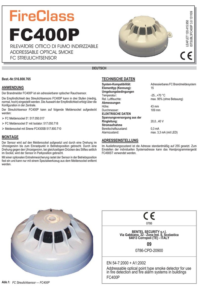
Bentel Security
Bentel Security FireClass FC400P User manual
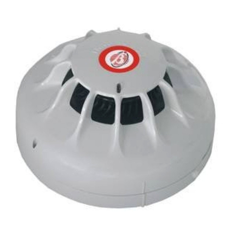
Bentel Security
Bentel Security FC400P User manual

Bentel Security
Bentel Security ZT100P User manual
Popular Smoke Alarm manuals by other brands
Siemens
Siemens FDA2 Series Planning, Mounting
Calex
Calex Smart 429220 quick guide
System Sensor
System Sensor A05-1003 Installation and maintenance instructions
Teletek electronics
Teletek electronics SensoIRIS MCP150 installation instructions

DMtex
DMtex S9000 instruction manual
B-Link
B-Link FUME instructions

