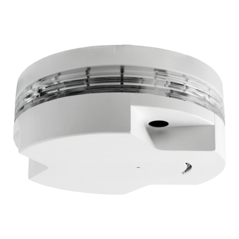
TESTING
1) All the alarm signal services, releasing device and extinguisher system
should be disengaged during the test period and must be re-engaged
immediately at the conclusion of testing.
2) After energizing the detector head for approximately one minute, check
to see the indicator green LED flashing once every 3~5 seconds. If
green LED fails to flash, it indicates the non-functioning of the detector
or faulty wiring. Re-check the wiring or replace the detector if necessary.
3) Allow smoke from a cotton wick or a test smoke aerosol to enter the de-
tector-sensing chamber for at least 10 seconds. When sufficient smoke
has entered the chamber, the detector will signal an alarm, this being
visible by a continuous illumination of the LED. Reset each detector
and/or control unit before attempting to test any additional detectors in
the same zone. If the alarm fails in this step, it indicates a defective unit,
which requires service.
SPECIFICATION
http:www.bentelsecurity.com
MAINTENANCE
The recommended minimum requirement for detector maintenance con-
sists of an annual cleaning of dust from the detector head by using a vacuum
cleaner cleaning program should be agreed to the individual environment.
+CAUTION: DO NOT ATTEMPT TO DISASSEMBLY OF THE
FACTORY SEALED SMOKE DETECTOR. THIS ASSEMBLY IS
SEALED FOR YOUR PROTECTION AND IS NOT INTENDED TO BE
OPENED FOR SERVICING BY USERS. OPENING THE DETECTOR
HEAD WILL VOID THE WARRANTY.
RECYCLING INFORMATION
BENTEL SECURITY recommends that customers dispose of their used
equipments (panels, detectors, sirens, and other devices) in an environ-
mentally sound manner. Potential methods include reuse of parts or whole
products and recycling of products, components, and/or materials.
For specific information see
www.bentelsecurity.com/en/environment.htm
WASTE ELECTRICAL AND ELECTRONIC EQUIPMENT (WEEE)
DIRECTIVE
In the European Union, this label indicates that this product
should NOT be disposed of with household waste. It should be
deposited at an appropriate facility to enable recovery and re-
cycling.
For specific information see
www.bentelsecurity.com/en/environment.htm
BENTEL SECURITY s.r.l. reserves the right to change the technical specifi-
cations of this product without prior notice.
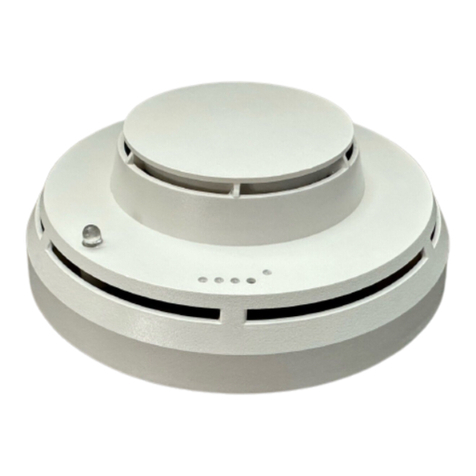
LED
RELAY
JUMPER SETTING
SMOKE CHAMBER
FIG. 3 Schematic of detector structure
Model 2/4 wire Voltage DC
Standby
Current
(Max.)
Alarm
Current
(Max.)
Surge
Current
(Max.)
Start-Up
Time
(Max.)
Permissible
Current
(Max.)
Frequency Alarm
contact
ZT100P 228/12 V 90 µA50 mA 120 µA60 s 80 mA 3-5 s
ZT100PL 228/12 V 90 µA50 mA 120 µA60 s 80 mA 3-5 s
ZT100PR1 412 V 320 µA35 mA 120 µA60 s 80 mA 3-5 s Form A
ZT100PR2 424 V 320 µA35 mA 120 µA60 s 80 mA 3-5 s Form A
