Bentone B40 MF Technical specifications

Providing sustainable energy solutions worldwide
178 129 53-3 CR00505 2025-05-19
Installation- and maintenance instruction
B 40 MF
LMO24.255C2E
E4NC-1069
Translation of the original instructions.

2Bentone
example Beispielexempel
352011030141
Designation
Type
Model
Serial no.
Motor supply
Main supply
MADE IN SWEDEN BY
LIGHT OIL 35-90kW 1,25-6,0 cSt 7-14bar
BF 1 KS 76-24
BF 1
BF 1 KS 76-24
1234567
1~230V 1,0A 50Hz IP 20
Man.Year 2019
Cap. Min-Max
3
?
1
-sv
1. Manualer på övriga språk
2. www.bentone.com\
nedladdning
eller scanna QR-koden.
3. Skriv in brännarens
artikelnummer som nns på
din
typskylt (se bild) och välj ditt
språk.
Detaljerad ecodesign
information kan laddas ner
på:
www.bentone.com/
ecodesign.
-en
1. Manuals in other languages
2. www.bentone.com\
download
or scan QR-code.
3. Enter the burner`s article
number on your data plate
(see picture) and select
language.
Detailed ecodesign
information can be
downloaded at:
www.bentone.com/
ecodesign.
-da
1. Manualer på andre sprog
2. www.bentone.com\
download eller scan QR-
koden.
3. Indtast brænderens
artikelnummer, der ndes
på typeskiltet (se billede), og
vælg dit sprog.
Detaljerede oplysninger om
ecodesign kan downloades
på: www.bentone.com/
ecodesign.
-fr
1. Manuels dans d’autres
langues
2. www.bentone.com\
download
ou scannez le code QR.
3. Saisir le numéro d’article
du brûleur sur votre plaque
signalétique (consultez
l’illustration) et sélectionnez
la langue.
Des informations détaillées
sur l’écodesign peuvent être
téléchargées à l’adresse:
www.bentone.com/
ecodesign.
-de
1. Gebrauchsanweisungen in
anderen Sprachen
2. www.bentone.com\
download
oder scannen Sie den QR-
Code.
3. Geben Sie die
Artikelnummer des Brenners
auf Ihrem Typenschild ein,
(siehe Bild) und wählen Sie
die Sprache aus.
Detaillierte Informationen
zum Ecodesign können unter
www.bentone.com/ecodesign
heruntergeladen werden.
2

3Bentone
General
Table of contents
1. Safety Information...............................................................4
2. Technical data.......................................................................7
2.1 Dimensions B 40 MF..................................................................... 7
2.2 ElectricSpecication..................................................................... 8
2.3 Settingofbrakeplateandairow ............................................ 9
2.4 Recommendednozzleandpressure ........................................ 9
2.5 Burnerinstallation ........................................................................ 9
2.6 Oilgrades......................................................................................10
2.7 Nozzleforbiooils,20-28bar....................................................11
2.8 Nozzleforfossiloils,22-28bar ................................................12
2.9 Description B 40 MF ..................................................................13
3. Installation..........................................................................15
3.1 Acceptanceinspection............................................................... 15
3.2 Preparationsforinstallation .....................................................15
3.3 Distributionofoil.........................................................................15
3.4 Electricalconnection ..................................................................16
3.5 Nozzleselection...........................................................................17
3.6 Settingofbrakeplateandairow ..........................................17
3.7 Burnerinstallation ......................................................................18
3.8 Checkoillineseals......................................................................18
4. Function description..........................................................19
4.1 B40MF1-stageburner............................................................. 19
5. Basic settings......................................................................20
5.1 ExamplesofbasicsettingB40MF..........................................20
5.2 Settingvaluesfornozzleandairdamper.............................. 20
5.3 Nozzleassemblycontrol,brakeplate .....................................21
5.4 Air setting B 40 MF......................................................................21
6. Burner servicing.................................................................22
6.1 Servicingthecombustionassembly ......................................22
6.2 Servicingairdampers ...............................................................23
6.3 Replacementofoilpump ..........................................................24
6.4 Replacementofpreheaters ......................................................25
6.5 Replacementofelectricalcomponents.................................. 26
6.6 Replacementofpreheateroverheatingprotector............... 26
6.7 Checkoillineseals......................................................................27
6.8 Checkpressurepistonnozzleholderseals ...........................27
6.9 Replacementofpressurepistonandseat.............................28
6.10 Immersionheatersforextrapreheating ............................... 29
6.11 Check/serviceoilpre-lter.........................................................31
7. Preheater ............................................................................32
7.1 Technicaldata ..............................................................................32
7.2 Adjustmentofpreheateroperatingthermostat ..................33
7.3 ReturnOilPressureSwitch........................................................ 34
8. Pump instruction E4NC-1069............................................35
8.1 Technicaldata ..............................................................................35
8.2 Components.................................................................................35
8.3 Oil connection..............................................................................35
8.4 Changingthelter......................................................................35
8.5 Function ........................................................................................36
8.6 Preheatingpump ........................................................................36
9. Electrical equipment .........................................................37
9.1 WiringdiagramLMO24.255... ................................................37
9.2 ComponentlistLMO24.255....................................................38
9.3 ColourcodesLMO14/24............................................................39
9.4 FaultcodesLMO14/24............................................................... 39
10. Fault Location.....................................................................40
10.1 Burnerwillnotstart....................................................................40
10.2 Burnerwillnotstartafternormaluse ....................................40
10.3 Delayedignition ..........................................................................41
10.4 Noiseinpump .............................................................................41
10.5 Pumppressure ............................................................................ 42
.....................................................43

4Bentone
1. Safety Information
This Installation and Maintenance manual:
• is to be regarded as part of the burner and must always be kept near
the installation site
• is intended for use by authorised personnel
• must be read prior to installation
• must be observed by all who work with the burner and associated
system components
• work with the burner may only be carried out by certied installers/
personnel
• Enertech AB is not liable for any typographical errors and reserves the
right to make design changes without prior notice.
• The burner may only be used for its intended purpose in accordance
with the product’s technical data.
• The burner may only be installed and operated by authorised
personnel.
• The product is packaged to prevent damage from occurring during
handling. Handle the product with care. Lifting equipment must be
used to lift larger packages.
• The products must be transported/stored on a level surface in a dry
environment, max. 80% relative humidity, no condensation.
Temperature -20 to +60 °C.
• Check that the burner is compatible with the boiler’s output range.
• The label information on the rating plate refers to the burner’s
minimum and maximum power.
• The power data on the type sign refers to the burner’s min. and max.
power.
• All components must be installed without being bent, twisted or
subjected to mechanical or thermal forces which can affect the
components.
• The burner must be installed so that it complies with local regulations
for re safety, electrical safety, and fuel distribution.
• Make sure when installing the equipment that there is enough space
to service the burner.
• Permitted ambient temperature during operation -0 to +60 °C. Max
80% relative humidity, no condensation.
• The installer must ensure that the room has adequate air supply.
• The room must comply with local regulations pertaining to its
intended use.
• The installation site must be free of chemicals.
• Burner pipes, fan wheels and air dampers may contain sharp edges.
• The surface temperature of the burner’s components can exceed 60
°C.
• Caution: The burner has moving parts, and there is risk of crushing
injuries.
• The electrical installation must be professionally carried out in
accordance with applicable high voltage regulations, as per Enertech’s
recommendations.
• Before servicing, shut off the fuel supply and turn off the power to the
165 105 60

5Bentone
burner.
• Leak checks must be performed during installation and servicing to
prevent fuel leakage.
• Care should be taken by the installer to ensure that no electrical
cables or fuel lines are crushed or otherwise damaged during
installation or servicing.
• If the boiler is equipped with an access hatch, this must be equipped
with a hatch opening switch connected to the burner's safety system.
• When in operation, the burner’s noise level can exceed 85 dBA.
Use hearing protection.
• The burner must not be put into operation without proper safety and
protection devices.
• A Class BE re extinguisher is recommended.
• It is forbidden to alter thedesign or use accessories which have not
been approved by Enertech in writing.
• Prior to operation, the following points must be checked:
-fitting and installation work has been completed and approved
-electrical installation has been correctly performed
-flue gas ducts and combustion air ducts are not blocked
-all actuators and control and safety devices are in working order and
correctly set

6Bentone
Components Service life – Recommended
replacement
Service life – Recommended
replacement Operating starts
Control system 10 years 250 000 starts
Pressure switch 10 years 250 000 starts
Flame guard 10 years 250 000 starts
UV ame sensor 10 000 hrs N/A
Damper motor 500 000 starts
Contaktor 10 years 500 000 starts
Gas valve with seal testing Replacement upon fault detection N/A
Gas pressure switch 10 years 250 000 starts
Safety blow-off system 10 years N/A
Damper motor N/A 500 000 starts
Contactor 10 years 500 000 starts
Pressure piston max. load,
Pressure piston min. load
+ O-ring, Valve seat
10 years 80 000 starts
Burner 1 year 3 000 hrs
Filter 1 year 3 000 hrs change
Oilhose 1 year control/change
Nozzle 1 year change 3 000 hrs change
Electrods 1 year change /cleaning 3 000 hrs change /cleaning
Brake plate 1 year change /cleaning 3 000 hrs change /cleaning
Motor 1 year 3 000 hrs
Cuppling chaft 1 year control/change 3 000 hrs control/change
Fan wheel “1 year change when dirty /
unbalance”
“3 000 hrs change when dirty /
unbalance”
Pressure piston max. load
Pressure piston min. load
Regular checks of seal and function
every 3 month. Change at leakage.
Control 2 000 hrs
Oil lter 2 year 3 000 hrs change
Oil valve Tightness check 2 year Replacement in case of leakage
The burner and its components must be recycled according to applicable regulations.
Burner servicing schedule
Servicing must be carried out once a year or after 3000 hours of operation
Component replacement intervals
Delivery check
• Make sure everything is delivered and the goods have not been
damaged during transit.
• If something is wrong with a delivery, report it to the supplier.
• Transport damage must be reported to the shipping company.

7Bentone
165 205 77-2
2. Technical data
The burner is intended for:
• Light oil, B10 heating oil/biofuel blend, FAME, B-100 (RME) (as dened in DIN V51603-6)
rapeseed DIN 51605:2010-10.
and is used for:
• Water heating generators.
• Hot air generators (these require LMO 24 255 C2E).
2.1 Dimensions B 40 MF
* Min. recommended distance to oor.
A Ø B Ø C D E F G H I * J
B 40 MF 202 160 114 527 262 316 362 202 451 200
I
H
A
D
E
F
G
B
C

8Bentone
Type Motor Complete burner Sound
B 40 MF 450W 230V 50/60Hz
10µF 230V 3,5A 400V 8,5A 50Hz 84 dBA ± 0,5 dBA
Max operating current, see data plate.
Working eld B 40 MF
2.2 Electric Specication
* Used lower caloric value of 10.00 kWh/kg for
rapeseed oil in accordance with DIN 51605:2010-10
-
1,0
0,0
1,0
2,0
3,0
4,0
50 100 150 200 250 300
mbar
kW
6.5-29.5 kg/h
65-300 kW
160303-224

9Bentone
2.4 Recommended nozzle and pressure
Nozzle: 45° Solid/semisolid
60° Solid/semisolid
80° Solid/semisolid
Pump pressure 10 bar (8-25 bar) depending on pump model
2.5 Burner installation
2.5.1 Hole patten
Make sure the hole pattern on the boiler is designed for burner ange.
Because of the various boiler types with varying furnace geometries and
furnace loads, it is impossible to commit to a certain scattering angle or a
specic distribution pattern.
It should be noted that the scattering angle and distribution pattern changes
with pump pressure.
d1
d2
d3
Combustion device d1d2d3
B 40 MF ø (115) 165 M14 ø 200-250
Burner correspond to IP 20
2.3 Setting of brake plate and air ow
a
b
e
c
d
a b c d e
B 40 MF 2,5-3,0 2,0 6,5-7,0 2,0 5,0
!*NB It is important
that the spark does
not strike against the
brake plate or nozzle
!

10 Bentone
!Altered structure of the oil can give rise to altered viscosity, pumpabilty and ignitability. This can
cause the pump, valves and nozzles to get blocked
2.6 Oil grades
The burner is tested and approved for pure rapeseed oil that complies with
standard DIN 51605:2010-10.
The burner is designed to be able to burn oils with a higher viscosity, both
of biological and fossil origin. The maximum viscosity with which the burner
is tested is 75 mm²/s, 0–130°c. Another way of dening which kind of oil
the burner can handle is that the oil must be of such a nature that it can be
pumped by the burner pump at the temperature the oil has at the point of
access to the pump.
The burner, without the pump, is designed to withstand the more corrosive
environment often created by oils of biological origin.
The Suntec E1069 pump is NOT designed for aggressive oils.
The burner pump has a service life of approx. 3–5 years if the oil is of a grade
that complies with standard DIN 51605:2010-10. If oil of a different grade
is used, especially if the oil contains contaminants such as particles, press
residue, metal swarf etc., or has chemical aggression, the pump may be
expected to have a signicantly shorter service life.
The pump is considered to be a wearing part and is not covered by the
warranty.
Pressure at the pump inlet must be -0.30 to max 2.0 bar. If there is a noise
from the pump, the oil is not pumpable at the current temperature or ow.
A transport oil pump combined with preheater is then needed to supply the
burner’s pump with oil for trouble-free operation.
The oil distribution system must be designed with the required equipment
such as lters, transport oil pump, preheater and reduction valve to provide
trouble -free operation. Max lter size is 120 µm and the oil may need to be
ltered in several steps.
In the case of a standstill in which the oil can be expected to change structure,
for example aging or phase transitions due to temperature and storage, the
burner must be ushed with fuel oil after the standstill. This procedure ensures
a good start after standstill.

11Bentone
2.7 Nozzle for bio oils, 20-28 bar
Pump pressure bar
Rapeseed oil compliant with DIN 51605:2010-10 Viscosity: 36.0 mm2/ s, at 40 °C preheater 160 °C
Gph 20 22 24 26 28
kg/h kW kg/h kW kg/h kW kg/h kW kg/h kW
1,00 4,9 49 5,2 51 5,4 53 5,6 56 5,8 58
1,50 7,4 73 7,7 77 8,1 80 8,4 84 8,7 87
2,00 9,8 98 10,3 103 10,8 107 11,2 112 11,6 116
2,50 12,3 122 12,9 128 13,5 134 14,0 140 14,5 145
3,00 14,8 147 15,5 154 16,2 161 16,8 168 17,5 174
3,50 17,2 172 18,0 180 18,9 188 19,6 196 20,4 203
4,00 19,7 196 20,6 206 21,5 215 22,4 224 23,3 232
4,50 22,1 221 23,2 232 24,2 242 25,2 252 26,2 261
5,00 24,6 245 25,8 257 26,9 269 28,0 280 29,1 290
5,50 27,0 270 28,4 283 29,6 296 30,8 308 32,0 320
6,00 29,5 295 30,9 309 32,3 323 33,6 336 34,9 349
6,50 32,0 319 33,5 335 35,0 350 36,4 364 37,8 378
7,00 34,4 344 36,1 361 37,7 377 39,2 392 40,7 407
7,50 36,9 368 38,7 386 40,4 404 42,0 420 43,6 436
8,00 39,3 393 41,3 412 43,1 430 44,9 448 46,5 465
8,50 41,8 418 43,8 438 45,8 457 47,7 476 49,5 494
9,00 44,3 442 46,4 464 48,5 484 50,5 504 52,4 523
9,50 46,7 467 49,0 489 51,2 511 53,3 532 55,3 552
10,00 49,2 491 51,6 515 53,9 538 56,1 560 58,2 581
10,50 51,6 516 54,1 541 56,6 565 58,9 588 61,1 610
11,00 54,1 540 56,7 567 59,3 592 61,7 616 64,0 640
11,50 56,5 565 59,3 593 61,9 619 64,5 644 66,9 669
12,00 59,0 590 61,9 618 64,6 646 67,3 672 69,8 698

12 Bentone
2.8 Nozzle for fossil oils, 22-28 bar
Pump pressure bar
The table applies to oil with a viscosity of 4.4 mm 2/s at a density of 830 kg/m 3.
Gph 22 24 26 28
kg/h kW kg/h kW kg/h kW kg/h kW
1,00 5,52 65,44 5,76 68,35 6 71,14 6,22 73,83
1,50 8,66 102,73 9,05 107,3 9,42 111,68 9,77 115,9
2,00 11,01 130,53 11,5 136,33 11,96 141,9 12,42 147,25
2,50 13,78 163,42 14,39 170,69 14,98 117,66 15,55 184,37
3,00 17,21 204,06 17,97 213,13 18,7 221,83 19,41 230,21
3,50 19,13 226,93 19,89 237,02 20,8 246,7 21,59 256,01
4,00 21,06 249,8 22 260,9 22,9 271,56 23,76 281,81
4,50 23,88 283,22 24,94 295,81 25,96 307,89 26,94 319,51
5,00 27,44 325,44 28,66 339,91 29,83 353,79 30,96 367,14
5,50 31 367,66 32,38 384 33,7 399,68 34,97 414,77
6,00 34,71 411,63 36,25 429,94 37,73 447,49 39,16 464,39
6,50 38,71 459,13 40,43 479,55 42,08 499,13 43,67 517,97
7,00 41,38 490,8 43,22 512,62 44,99 533,55 46,69 553,69
7,50 44,2 524,22 46,17 547,53 48,05 569,89 49,86 591,4
8,00 46,72 554,12 48,8 578,76 50,79 602,4 52,71 625,14
8,50 49,1 582,27 51,28 608,16 53,37 632,99 55,39 656,89
9,00 52,51 622,73 54,84 650,42 57,08 676,98 59,24 702,53
10,00 55,92 663,19 58,4 692,68 60,79 720,96 63,08 748,18
11,00 63,04 747,63 65,84 780,87 68,53 812,76 71,12 843,44
12,00 70,75 839,1 73,9 876,41 76,91 912,2 79,82 946,63

13Bentone
21
23
27
24
26 25
22
13
4
9
6
587
3
10
2
15 12 1114
1
17
18
19
16
20
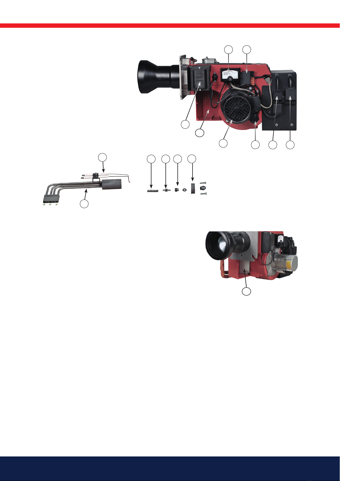
2.9 Description B 40 MF
2.9.1 Components B 40 MF
1. Indicator lamp, preheater ON
2. Inspection glass
3. Immersion heater, pump
4. Fan housing
5. Nozzle assembly control
6. Scale, nozzle assembly control
7. Solenoid valve NO
8. Valve block
9. Burner tube
10. Cavity immersion heater valve block
11. Pressure outlet pump
12. Return pump
13. Pump
14. Pressure control pump
15. Inlet pump
16. Nozzle assembly
17. Brake plate
18. Nozzle
19. Cavity immersion heater nozzle holder
20. Preheater
14 Bentone
41
16
28 29 30 31
39
38
40
37 3536
33 34
32
1. Fan wheel
2. Measuring nipple, fan pressure
3. Burner ange
4. Connecting pipe, valve block return
5. Damper motor
6. Connecting pipe, preheater valve block
7. Connecting pipe, pump preheater
8. Ignition electrodes
9. Spring pressure piston
10. Preheater
11. Valve seat
12. Front nozzle holder
13. Relay box
14. 7-pole Europlug (feed)
15. 5-pole Euro plug (feed preheater)
16. 4-pole Euro plug (control signal preheater)
17. Capacitor
18. Motor
19. Air intake
20. Ignition transformer
21. Air damper

15Bentone
165 205 78
1
3. Installation
3.1 Acceptance inspection
Make sure everything is delivered and the goods have not been damaged
during transit. If something is wrong with the delivery, report it to the supplier.
Transport damage must be reported to the shipping company.
3.2 Preparations for installation
Check that the burner's dimensions and capacity range are suitable for the
boiler in question. The power data on the type sign refers to the burner's min.
and max. power.
3.3 Distribution of oil
In order to achieve good reliability, it is important that the oil distribution
system is designed correctly.
Take the following into account:
• Selection of pipe diameter, pipe length and height difference; see
Pump instruction.
• Pipelines are to be laid with a minimal number of glands.
• The pipes are to be laid so that the oil supply hoses are not subjected
to tensile stresses or are excessively bent when the burner is swung
out or removed for service.
• The ½ " oil lter should be installed so that the lter cartridge can
easily be replaced or cleaned. Self-cleaning lters are recommended
for oils of a higher viscosity or oils that contain signicant impurities.
• Oil-affected parts shall be selected in materials that are capable of
withstanding the medium's physical properties.
• When installing oil hoses, check that the inlet and return hoses are
tted to the appropriate connection on the oil pump. The hoses shall
be located so that they do not bend or become subject to tensile load.
To the suction line on the pump (see paragraph 7.2 pos. 3) should the
supplied oil hose with 90° bend be connected.
• Bleed the oil system. The oil pump/oil preheater may be damaged
if run dry. The vacuum should not fall below 0 bar in the suction line
during start-up.
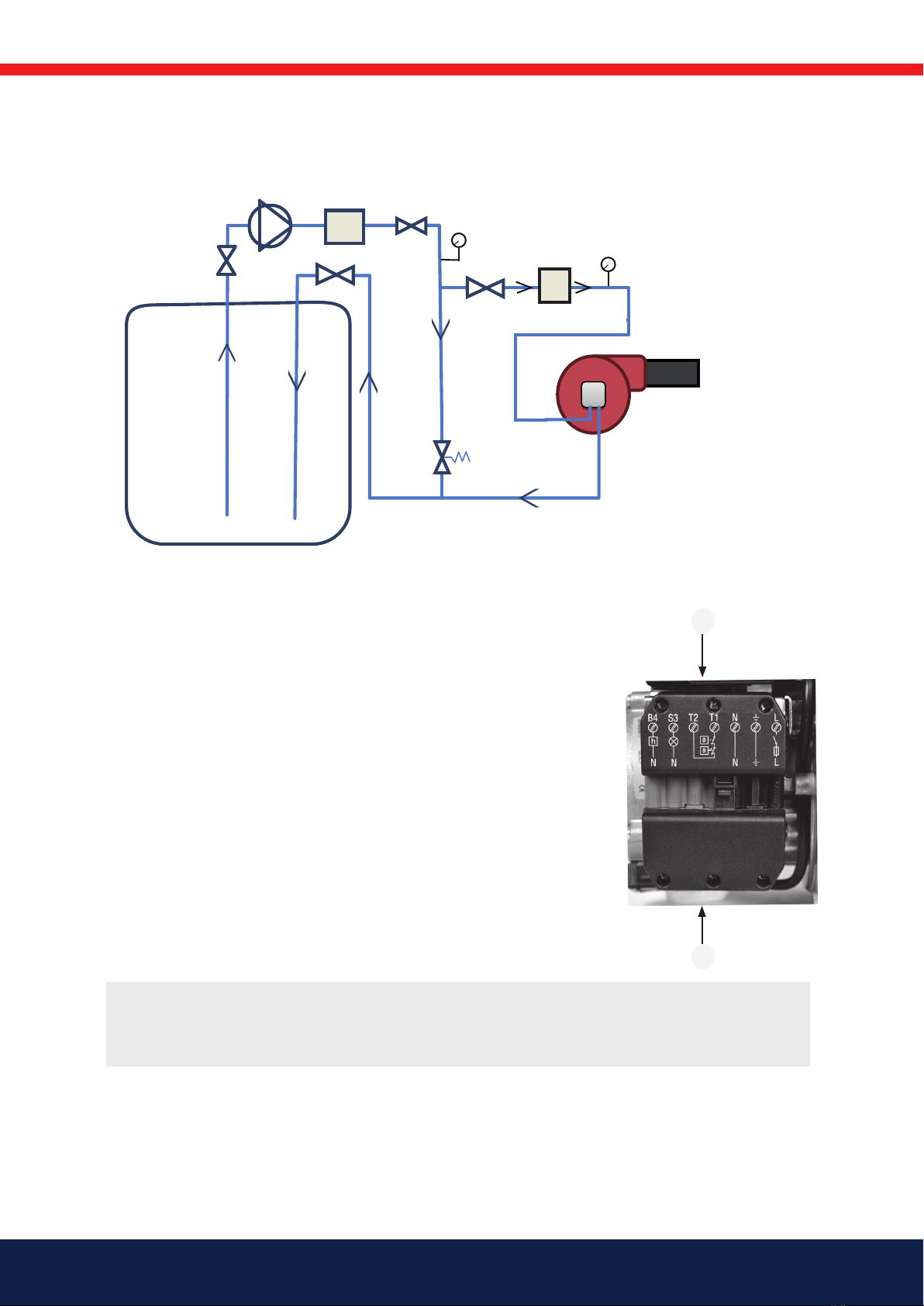
3.3.1 Proposed pipe routing for oil distribution systems
without transport pump
This type of connection should be used only when the oil has a viscosity less
than 30 mm²/s.
1. Self-cleaning lter
!
burner oil system
before starting it for the
16 Bentone
X3
X4
1. Transport oil lter
2. Basket lter
3. Overow valve 0.5 – 2.0 bar
4. Seal lter
5. Pressure gauge 1
6. Pressure gauge 2
3
2
1 Transport oil pump / Transportoljepump
4
5
6
1
!If any electrical connection is used other than that recommended by Bentone, there may be a
danger of damage to property and personal injury.
3.3.2 Proposed pipe routing for oil distribution systems with transport pump,
basket lter and seal lter
3.4 Electrical connection
Before electrical installation begins, the main power switch must be turned off.
If the boiler has a 7-pole and a 4-pole Euro plug connector, they will usually
connect directly to the burner. Otherwise, use the supplied connectors. The
5-pole connector supplies the burner preheater with a separate 3-phase
supply. See connection under Electrical equipment.
1. Switch off the main switch.
2. Connect the Euro plugs. (See Electrical equipment)
3. Make sure the burner operations switch (S1) is off.
4. Turn on the main switch.

17Bentone
3.5 Nozzle selection
See under Technical data: Recommended nozzle and Nozzle table.
If, after selecting the nozzle, burner type B45-2 MF has diculty starting, this
may in some cases be due to the selection of nozzle made for the rst stage.
Selecting a nozzle with a smaller effect in the rst stage may solve the problem.
3.6 Setting of brake plate and air ow
Prior to commissioning, the basic settings of the burner can be set in
accordance with the diagram. See under Basic settings. Note that it is simply
a matter of a basic setting that should be adjusted retrospectively once the
burner has started. You should then conduct a ue gas analysis and soot
quantity measurement.
18 Bentone
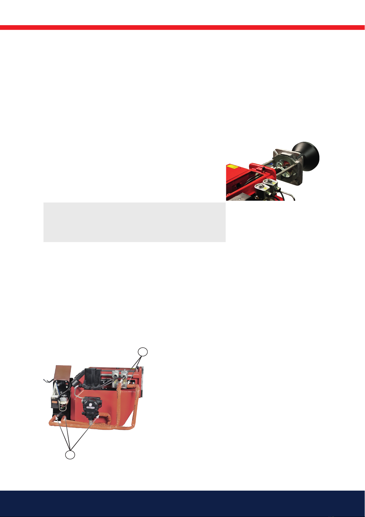
A
A
3.7 Burner installation
1. Separate the burner body and the ange.
2. Remove the brake plate from the oil pipe.
3. Install the selected nozzle. (See Technical data)
4. Install the brake plate on the oil pipe
5. Remove the burner tube from the ange.
6. Install the ange with gasket on the boiler.
7. Install the burner tube on the ange. Make sure that the hole in the
front of the burner tube pipe is pointing down. This allows any drops
of oil to ow out.
8. Insulate between the burner and boiler door to reduce radiated heat.
9. Fit the burner body on the ange.
10. Lock the burner body using with the nut/nuts.
11. Connect the oil hoses to the pump, see paragraph 2.3
12. Connect burner electrically, see paragraph 2.4
3.8 Check oil line seals
Once the burner has been installed and commissioned, the seals of the various
coupling elements should be checked (A). These may, due to temperature
uctuations or transportation, start to leak.
Temperature uctuations arise from the process of heating oil used in these
burners.
When a leak is detected, it is usually sucient to tighten the coupling element
that is leaking.
!Because the burner tube must be installed from the inside the
boiler, it must be possible to open the boiler or have a hinged
ange that is designed so that it can be reconnected with the
burner tube installed.

19Bentone
165 205 79
E1P
Y1
I
N
Y1
1
L
V1
4. Function description
4.1 B 40 MF 1-stage burner
When the installation calls for heat, the burner's preheater starts to heat the
oil. Once the oil reaches the set temperature, the burner receives the signal to
start. Hot oil is ushed throughout the burner's oil system.
After the end of the blow period, the solenoid valve (Y1) receives voltage and
closes. The oil pressure builds up in the nozzle holder and the cut valve (V1)
opens. The oil is atomised in the nozzle and ignited. A small amount of oil and
the nozzle assembly compressed air ow is channelled back to the return side
of the pump through the leak oil line (L).
Once the installation has reached the desired temperature, a solenoid valve
(Y1) is rendered without power and then opened; cut valve (V1) is then closed.
This process extinguishes the burner ame. In the same process, oil heating is
also interrupted.
P Oil pump
E1 Preheater
I Nozzle assembly
L Leak pipe
N1 Nozzle 1
Y1 Solenoid valve 1 NO
V1 Cut valve

20 Bentone
165 205 80-2
5. Basic settings
5.1 Examples of basic setting B 40 MF
Burner output 200 kW
Estimated nozzle output 200 kW/10 kWh/kg*= 20 kg/h
Nozzle selection in accordance with the table. (See technical data) Nozzle
selection is based on the selected pump pressure and the desired effect.
According to the nozzle table, this provides the following nozzle.
Selected pump
pressure
25 bar
Nozzle 3.50 gph
Power in 20.61 kg/h => 20.61 kg/h x 10 kWh/kg* = 206 kW
* Taken from the fuel in accordance with standard DIN 51605:2010-10
Effects and nozzle selection from example
Nozzle assembly 14
Damper 7
Basic settings should only be seen as setting values to get burner to start and
establish a ame. Once the burner has started and established a ame, it will
be necessary to adjust the settings so that they are adapted to the installation
in question and the fuel used at the time.
Basic settings
The setting value for 200 kW in accordance with basic setting tables. For the
correct procedure when implementing settings, see 4.7 Nozzle assembly
control, brake plate B40 MF and 4.8 Air setting B40 MF (See technical data )
5.2 Setting values for nozzle and air damper
0
10
20
30
50 100 150 200 250 300
160303-225
kW
Air settings
Nozzle assembly
Scale
Burner output
Other manuals for B40 MF
2
Table of contents
Other Bentone Industrial Equipment manuals


