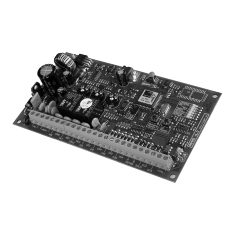
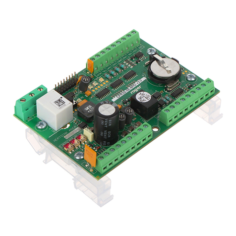
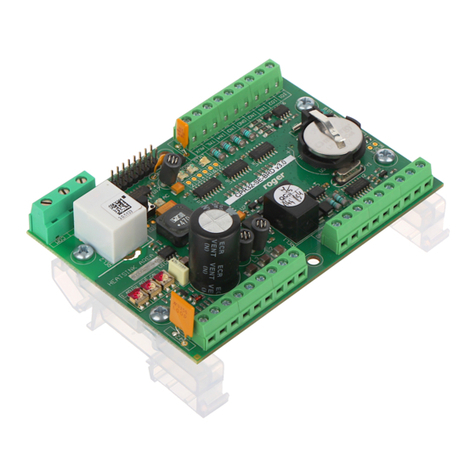
Roger PR311SE Instruction and safety manual

© 2016 ROGER sp. z o.o. sp.k. All rights reserved. This document is subject to the Terms of Use in their current version published at
the www.roger.pl website of the Roger sp. z o.o. sp.k. company (hereinafter referred to as ROGER).
Roger Access Control System
Functional description of PRxx1 series controllers
Document version: Rev.H
This document refers to the following products:
PR311SE, PR311SE-BK, PR611, PR611-VP, PR621, PR411DR, PR411DR-BRD

Functional description of PRxx1 series controllers Rev.H.doc
2016-10-28
2/43
Contents:
I. General........................................................................................................................... 4
1.1 Introduction....................................................................................................................... 4
1.2 Design and Architecture...................................................................................................... 4
1.3 Features of PRxx1 series controllers .................................................................................... 7
II Functional Description .................................................................................................. 8
2.1 Available scenarios of operation .......................................................................................... 8
2.1.1 Standalone System ........................................................................................................ 8
2.1.2 Network System (with CPR32-SE)................................................................................... 9
2.1.3 Network System (without CPR32-SE) .............................................................................. 9
2.2 Communication ................................................................................................................ 10
2.2.1 RS485 communication bus ........................................................................................... 10
2.2.2 Controller address ....................................................................................................... 10
2.2.3 RACS Clock and Data Interface..................................................................................... 11
2.2.4 XM-2 - I/O Extension Module ....................................................................................... 12
2.2.5 Wiegand Interface Readers .......................................................................................... 12
2.3 Users............................................................................................................................... 12
2.3.1 Standard and Guest Users............................................................................................ 12
2.3.2 User Options ............................................................................................................... 13
2.3.3 Groups........................................................................................................................ 14
2.4 Identification Modes ......................................................................................................... 14
2.5 Door Modes ..................................................................................................................... 14
2.6 Armed and Disarmed Modes ............................................................................................. 15
2.6.1 Concept ...................................................................................................................... 15
2.6.2 Arming and Disarming ................................................................................................. 15
2.6.3 Time scheduled arming/disarming ................................................................................ 15
2.6.4 Option: Arm/Disarm Schedule ...................................................................................... 15
2.7 Access Rights................................................................................................................... 16
2.7.1 Access Signaling .......................................................................................................... 16
2.7.2 Door Lock Control........................................................................................................ 16
2.7.3 Option: Access Disabled when Controller Armed ............................................................ 17
2.7.4 Option: Door Lock Controlled in Latch Mode (toggle) ..................................................... 17
2.7.5 Option: Auto-relock mode ............................................................................................ 17
2.7.6 Facility Code................................................................................................................ 17
2.7.7 Option: Disable PIN under duress ................................................................................. 17
2.7.8 Option: Hotel room...................................................................................................... 18
2.7.9 System Flags............................................................................................................... 18
2.7.10 Door Alarm................................................................................................................ 20
2.7.11 Option: Enable Door Alarm signaling on internal buzzer ............................................... 21
2.7.12 Option: Device temporary blocked after 5 wrong logins................................................ 21
2.7.13 Option: Constant activation of Output 1 by card in vicinity of reader ............................. 22
2.7.14 Anti-passback (APB)................................................................................................... 22
2.7.15 Anti-passback Zones (APB Zones) ............................................................................... 22
2.7.16 Alarm Zones .............................................................................................................. 23
2.8 Inputs ............................................................................................................................. 24
2.9 Outputs ........................................................................................................................... 26
2.10 Function Keys ................................................................................................................ 29
2.11 Function Cards ............................................................................................................... 30
III. Programming ............................................................................................................ 32

Functional description of PRxx1 series controllers Rev.H.doc
2016-10-28
3/43
3.1 Memory Reset –Setting MASTER identifier and ID address of the controller ........................ 32
3.2 User Commands............................................................................................................... 33
3.3 Installer Programming Mode ............................................................................................. 35
3.4 Acoustic and visible signals ............................................................................................... 42
3.4.1 Visible signals.............................................................................................................. 42
3.4.2 Acoustic signals ........................................................................................................... 43
Typing conventions
Functions, options and commands
bold letter
Examples
italics letters
Specific names related to RACS system
with first capital letter
STATUS,FLAG OR TIMER
capital letters
Notes
separated with two lines (upper, lower)
from the standard text

Functional description of PRxx1 series controllers Rev.H.doc
2016-10-28
4/43
I. GENERAL
1.1 Introduction
This document applies to PRxx1 series standard controllers and includes devices with built-in reader
for installation near the door (PR311-SE, PR621, PR612) as well as device without built-in reader for
installation inside metal box preferably in some distance from door (PR411DR). PR621-CH and
PR821-CH controllers are equipped with card holder and functionally are similar to PR621 controller.
Therefore in the present document, the name PR621 can also apply to both PR621-CH and PR821-
CH. The only difference between PR311-SE-BK and PR311-SE is lack of keypad in the first one. The
controller PR411DR is available both in plastic enclosure for installation on DIN 35mm rail
(PR411DR) or as electronic module (PR411DR-BRD). The name PR411DR applies to all possible
models of this controller.
This document does not apply to older type controllers of following types: PR401, PR301 and
PR201.
1.2 Design and Architecture
The PRxx1 series controllers are single-door, two–way access controllers. Each PRxx1 controller can
work with two logical access points (readers) called respectively: Terminal ID0 and Terminal ID1.
All PRxx1 series controllers except for PR411DR are equipped with built-in reader of EM125kHz
standard, which is logically treated as Terminal ID1 and they can operate with one external reader
logically treated as Terminal ID0. The PR411DR controller is not equipped with any built-in reader
but it can work with two external readers. Generally, the PRxx1 controllers are designed to operate
with PRT series readers (from Roger) configured to RACS Clock&Data data protocol, however
PR411DR can also work with Wiegand 26-66bit readers as well.
Fig. 1 General architecture of controller and reader(s)

Functional description of PRxx1 series controllers Rev.H.doc
2016-10-28
5/43
PRxx1 controller can register up to 1000 users plus 8 special ones called Guests. Each user has its
own ID number and may have proximity card and/or PIN. Controller firmware can be upgraded on-
site by means of RS485 serial interface and what is important the firmware upgrade process does
not require unit to be removed from its original place of installation. PRxx1 controllers can operate
fully autonomously (Standalone System) or in the Network System with or without CPR32-SE
network controller. PRxx1 controllers can be programmed manually or from PC. Manual
programming can be performed locally using the device’s keypad or from remote keypad located on
the external PRT series reader and connected to the programmed controller (the external reader
which is used to program controller should be equipped with keypad and configured to RACS
Clock&Data mode with ID0 address) –see III. Programming. Later, for some user programming
functions a so called Function Cards can be used. Remote programming can be done by means of
PR Master software (Roger) installed on PC.
The communication with single controller and management of the whole access control system
requires a dedicated interface device e.g.:
UT-4DR or UT-4 (RS485 <-> Ethernet).
UT-2USB (USB <-> RS485),
UT-2 (RS-232 <-> RS485),
RUD-1 (USB <-> RS485).

Table 1. List of PRxx1 series controllers
Controller
PR311SE
PR311SE-BK
PR611
PR621
PR621-CH/PR821-CH
PR411DR
PR411DR-BRD
Power supply
12VDC
12VDC
12 VDC
12 VDC
12VDC
12 VDC, 24VDC,
18VAC
12 VDC, 24VDC,
18VAC
Programmable NO/NC
inputs
3
3
3
3
3
8
8
Programmable relay
outputs
1 x 1,5A/30V
1 x 1,5A/30V
1 x 1,5A/30V
1 x 1,5A/30V
2 x 5A/30V i 230VAC
1 x 1,5A/30V
1 x 1,5A/30V
1 x 5A/30V and
230VAC
1 x 5A/30V and
230VAC
Programmable
transistor outputs
1A/15VDC
2
2
2
2
2
2
2
Built-in EM 125kHz
reader
Yes
Yes
Yes
Yes
Yes
No
No
External PRT series
readers
1
1
1
1
1
2
2
External Wiegand 26-
66bit readers
No
No
No
No
No
2
2
Built-in keypad
Yes
No
Yes
No
No
No
No
Built-in function keys
Yes
No
No
No
No
No
No
Other
Outdoor
operation,
connecting cable
included (45 cm)
Outdoor
operation,
connecting cable
included (45 cm)
Outdoor
operation,
connecting
cable (45 cm)
or screw
terminals
included
Outdoor
operation,
connecting
cable (45 cm)
or screw
terminals
included
Outdoor operation,
connecting cable (45
cm) or screw
terminals included,
card holder
Installation on
DIN 35mm rail,
built-in
1.2A/12VDC
power supply
unit, possible
connection of
backup battery.
Electronic
module, built-in
1.2A/12VDC
power supply
unit, possible
connection of
backup battery.

1.3 Features of PRxx1 series controllers
Features of standard series PRxx1 controllers:
Single door, two-way access control
Operation in Standalone or Network System
Possible connection of PRT series readers (Roger)
Possible connection of Magstripe oraz Wiegand readers (only PR411DR)
User identification by means of prox. card or PIN
Programmable validity time for user prox. card or PIN
Limited number of accesses for users
Up to 1000 users
250 Access Groups
99 Schedules (*)
128 time periods within single Schedule (*)
4 Holiday Schedules (H1-H4) (*)
Automatic winter-summer time change (*)
Time and Attendance registration (*)
Built-in keypad (PR311SE, PR611)
Programmable inputs/outputs
Built-in 1.5A/30V relay output
Built-in 5A/230V relay output (PR411DR only)
Operation with XM-2 I/O module
Communication with controllers by RS485 bus
Firmware upgrade through RS485 serial port
Integration with CCTV systems
Management software for Windows XP/Vista/7
Outdoor operation (PR311SE, PR311SE-BK, PR611 and PR621)
DIN RAIL 35mm enclosure (only PR411DR)
Management through LAN/WAN (UT-4 interface required)
CE mark
(*) - features available only in Network Systems (see 2.1.2 Network System (with CPR32-SE))

Functional description of PRxx1 series controllers Rev.H.doc
2016-10-28
8/43
II FUNCTIONAL DESCRIPTION
2.1 Available scenarios of operation
2.1.1 Standalone System
If PRxx1 controller works autonomously i.e. without CPR32-SE network controller then it does not
offer neither time related functions (e.g. timed access rights) nor event log. In this mode, it is
possible to assign users to different Access Groups but their right are not time related. Within
Standalone system all users have full access rights 24h/7d or have no access depending on
settings. This mode enables defining of Access Zones. Controller can be programmed manually or
from PC by means of PR MASTER software.
Note: The standalone scenario does not exclude the possibility to connect with controller by means
of RS485 interface as well as programming from PC.
Fig. 2 Standalone System (offline)
Fig. 3 Standalone system (online)

Functional description of PRxx1 series controllers Rev.H.doc
2016-10-28
9/43
2.1.2 Network System (with CPR32-SE)
When controllers operate in a system equipped with CPR-32SE unit, users can be divided into 250
different Access Groups and be assigned to Schedules. CPR-32SE also provides event buffer, real
time clock and calendar plus global type functionalities like Alarm Zones and Global Anti-passback.
Also Access Zones can be specified by administrator. PC is required only for programming and
management of such Network System.
Fig. 4 Network System with CPR32-SE
2.1.3 Network System (without CPR32-SE)
In such configuration, PC and PR Master software in monitoring mode can emulate CPR32-SE
network controller. Therefore it is possible to assign users to particular Groups, Schedules and
Access Zones as well as define Door Modes and Identification Modes. The same pertains to such
global functions as Zone Alarms and APB Zones. Mentioned functionalities are available only if PC is
hardwired to communication interface, is always on and PR Master software is in monitoring mode.
In case of PC failure or PC turn off, access controllers automatically switch to Autonomous
(Standalone) Mode and continue their operation based on the settings available prior to failure/PC
disconnection. After recovery of communication with PC, access controllers automatically switch to
Network Mode and realize previously suspended functions, including Schedules.

Functional description of PRxx1 series controllers Rev.H.doc
2016-10-28
10/43
Fig. 5 Network System without CPR32-SE
2.2 Communication
2.2.1 RS485 communication bus
Communication with PRxx1 controllers is based on RS485 interface and devices in RS485 network
must have unique address (ID=00-99). A single communication bus may accommodate up to 32
access controllers (complete Network) and one optional CPR32-SE unit. The RACS4 system
communication topology of Network is fairly flexible i.e. tree structures as well as star topologies
are allowed, however loop topology is forbidden. Regular signal cables can be used and unshielded
twisted-pair wire is recommended. Terminating resistors at either end of the communication bus
are not required.
Maximum cable lengths in the RACS4 system are as follows:
Between any controller and CPR32-SE: 1200 m
Between any controller and interface device: 1200 m
Between CPR32-SE and interface device: 1200 m
Note: All devices connected to RS485 bus must share the same ground potential, and this condition
is clearly satisfied if all devices are supplied from the same power supply unit. If more than one
power supply unit is used, then negative DC terminals of each power supply unit need to be
connected with each other by means of additional wire (could be standard signal wire). If such
connection is not feasible for any reasons, negative DC output of each power supply unit should be
earthed separately, however, the difference of earth potential across all units cannot exceed +/-2V.
DO NOT short circuit positive terminals of power supply.
The structure incorporating RS485 communication bus, access controllers and optional CPR32-SE
unit is called an Access Control Network or simply a Network (or Subsystem). Each Network in the
RACS4 system must be connected to PC via a separate communication port. It can be the standard
COM Port, Virtual COM Port (VCP) or Ethernet port. In case of VCP, users can use interface device
(Roger), which emulates COM port, e.g. RUD-1 or UT-2USB. In case of Ethernet port, UT-4DR is
recommended
Each type of PRxx1 controller can manage single door in one-way or two-way mode. Presently,
RACS4 permits integration of up to 250 Networks (Subsystems), each including up to 32 controllers.
PC with PR Master software communicates with each Network by means of separate communication
port, which means that it is possible to integrate Networks connected to PC by means of following
interfaces: RS232, USB, Ethernet and Wi-Fi, thus creating one access control system.
Note: All mentioned communication interfaces can be used not only for controller programming but
also for the management of entire access control system, depending on applied scenario (see 2.1
Available scenarios of operation). In case of on-site programming, we recommend RUD-1 interface
device that provides built-in 12VDC output which can be used to supply programmed device.
2.2.2 Controller address
Each controller connected to RACS4 system communication bus (RS485) must have its own address
in range of 00-99. Default address is ID=00 and can be modified either remotely using PR Master
software (Roger) or manually (see 3.1 Memory Reset –Setting MASTER identifier and ID address of
the controller and 3.3 Installer Programming Mode) or by means of jumpers (only PR411DR).
Moreover, it is possible to assign a so called “FixedID” to the controller. This option is particularly
useful if there is a risk that someone will accidently change controller address resulting in disruption
of the whole system. The fixed address can be set, changed or cleared only by means of RogerISP
software during firmware upgrade procedure.
Besides mentioned methods of addressing, the PR411DR controller offers the option to set address
by means of programming jumpers. The whole range of possible address is 0-127. If controller

Functional description of PRxx1 series controllers Rev.H.doc
2016-10-28
11/43
address is set in range of 0-99 then it cannot be changed neither by means of PR Master nor
manually. It can be modified only if jumper address is set above 99. For details regarding various
address settings refer to the relevant Installation Guide.
Note: The fixed address (FixedID) has always the highest priority –if it is set then it can be
modified only using RogerISP software during firmware upgrade procedure.
2.2.3 RACS Clock and Data Interface
Besides the RS485 communication bus, PRxx1 controllers feature also the so-called RACS Clock &
Data interface (alternatively called: Internal Bus). This interface is used for communication with
external PRT series readers and/or XM-2 I/O extension module. RACS Clock&Data interface
incorporates two lines: CLK and DTA. The following devices can be connected to the internal bus:
Primary access reader (Terminal ID0, address ID=0)
Secondary access reader (Terminal ID1, address ID=1) (only PR411DR)
XM-2 input/output extension module (address ID=5)
Fig. 6 RACS Clock&Data interface
Note: If there are no devices connected to CLK and DTA lines then it is possible to configure these
lines as standard transistor type outputs, capable to sink up to 150mA/15VDC.
For CLK/DTA lines any type of signal cable can be used. There is no need to use either twisted or
shielded cables. The maximum cable length between controller and external reader and/or XM-2
extension module is limited to 150m. Similarly as in case of RS485 bus, all devices connected to
CLK/DTA line should have common negative terminals. Such condition is usually satisfied because
devices connected to CLK/DTA line are usually directly supplied from controller. Otherwise negative
terminal of each reader must be connected to respective controller GND or COM terminal.

Functional description of PRxx1 series controllers Rev.H.doc
2016-10-28
12/43
2.2.4 XM-2 - I/O Extension Module
The PRxx1 series controller can operate with single XM-2 I/O extension module. This module offers
two NO/NC inputs and two relay outputs. Both inputs and outputs of XM-2 can be programmed in
the same way as internal inputs/outputs of the controller. The XM-2 can be used to extend number
of available inputs and outputs and/or separate relay output connected to door strike. Such
separation of relay output might be required in case of PR302 and PR602LCD controllers as they
are installed near the door and can suffer from intrusion. The XM-2 module connected to controller
must be configured to address ID=5. Digital communication between controller and XM-2 module is
perforemed by means of RACS Clock&Data bus. For more information on XM-2 module refer to
Installation Guide, which is available at www.roger.pl.
2.2.5 Wiegand Interface Readers
Only PR411DR can work with Wiegand interface readers. The controller uses separate input lines in
order to connect with such readers, as presented in figure 6 below.
Fig. 7 Wiring for Wiegand interface readers
In general, Wiegand readers can be connected to PR411DR controller along with PRT series
readers. If so, users can login either on Wiegand or PRT reader.
2.3 Users
2.3.1 Standard and Guest Users
Each user programmed in the controller might have card and/or PIN (3-6 digits followed by #), also
he/she can be granted with 8 special User Options. All types of users are specified in table 2.
Table 2. User types
User type
ID
Description

Functional description of PRxx1 series controllers Rev.H.doc
2016-10-28
13/43
MASTER
000
MASTER has the highest privileges in the system and is allowed for
both door access and arming/disarming of the controller. The
MASTER has always fixed Op.1 = No and all other options Op.2-
Op.8 = Yes (see table 3)
SWITCHER
Full
ID=001-049
SWITCHER Full is allowed for both normal access and
arming/disarming of the controller. Double use of identifier is
required for arming/disarming and single use of identifier gives
door access.
SWITCHER
Limited
ID=050-099
SWITCHER Limited is allowed solely for arming/disarming of the
controller and is not allowed for door access. Single use of identifier
is required for arming/disarming.
NORMAL
ID=100..999
NORMAL is allowed solely for door access and by default is not
allowed to arm/disarm controller.
GUEST
ID=4000-4007
GUEST is defined individually in each controller in the system.
GUEST might be authorized for door access and for
arming/disarming.
Standard users (ID=000-999) are recorded in all controllers of the access control system and Guest
users (ID=4000-4007) are programmed individually on each controller. These users are
programmed and managed by means of special programming procedures. Optionally, for
management of Guest users there is a special programmer’s interface (API) which allows system
integrators to create special software dedicated to manage this kind of users. Every Guest user may
have card and/or PIN and can be granted with one or more special User Options as any other
standard user of the system. If the controller works in Network Access Control System (see 2.1.2
Network System) then Guest users can be assigned to the Access Group –as a result theirs access
rights will be under control of Schedule.
2.3.2 User Options
Eight special options (called Op.1 - Op.8) can be assigned to every individual user within particular
controller including Standard Users, Guest users and Facility Code cardholders as well. The options
define additional rights related to programming and management of particular controller.
Table 3: User options
Option
Name
Function
Op.1
Access completely disabled
When option is active, the user do not have access
rights at particular controller regardless of other
settings.
Op.2
Enabled for authorization of F1 key
at Terminal ID0
When option is active, the user will be allowed to
use F1 key at terminal ID0 (if such authorization is
required at all (see 2.10 Function Keys)
Op.3
Enabled for authorization of F2 key
at Terminal ID0
When option is active, the user will be allowed to
use F2 key at terminal ID0 (if such authorization is
required at all (see 2.10 Function Keys)
Op.4
Enabled for authorization of F1 key
at Terminal ID1
When option is active, the user will be allowed to
use F1 key at terminal ID1 (if such authorization is
required at all (see 2.10 Function Keys)
Op.5
Enabled for authorization of F2 key
at Terminal ID1
When option is active, the user will be allowed to
use F2 key at terminal ID1 (if such authorization is
required at all (see 2.10 Function Keys)
Op.6
Enabled for authorization of User
When option is active, the user will be allowed to

Functional description of PRxx1 series controllers Rev.H.doc
2016-10-28
14/43
Commands
apply User Commands (see 3.2 User Commands)
Op.7
Enabled for arming/disarming
When option is active, the user will be allowed to
arm/disarm particular controller.
Op.8
Enabled for authorization of
Function Cards
When option is active, the user will be allowed to
use Function Cards (see 2.11 Function Cards)
2.3.3 Groups
Users of RACS4 access control system can be divided into Groups or may belong to special (default)
group called: No Group or No Access Group. All users assigned to a particular user Group share the
same (identical) access rights. You can also define Group for single user. Members of particular
Group are granted access to particular areas in accordance with defined Schedules. Users belonging
to No Group are given unlimited 24h/7d access to all Access Zones, while users assigned to No
Access Group cannot open any door.
2.4 Identification Modes
Following Identification Modes are available for the purpose of user identification:
Table 4: Identification modes
Mode
Description
Card or PIN
Controller requires card or PIN
Card and PIN
Controller requires card and PIN
Card Only
Controller requires card only, PINs are not accepted
PIN Only
Controller requires PIN only, cards are not accepted
In case of PRxx1 controllers the same Identification Mode is set for both sides of door. Unless
modified by administrator, the controller applies default Identification Mode (i.e. Card or PIN).
Identification modes apply to all users at particular controller/reader and they can be set or
changed by:
Schedule (only Network System)
Function keys
Input lines
2.5 Door Modes
Door Modes determine rules for locking/unlocking of access controlled doors. Following Door Modes
are available in RACS4 system:
Table 5: Door Modes
Mode
Description
Normal
Normally the door is locked and opened only for the time of granted
access.
Unlocked
The door is unlocked permanently. No identification is required to enter
or exit.
Conditionally unlocked
Initially, the door is in the Normal Mode. As soon as the first user is
granted an access, the controller switches to the Unlocked mode.
Locked
The door is locked permanently for all users regardless of their access

Functional description of PRxx1 series controllers Rev.H.doc
2016-10-28
15/43
rights.
Default mode is always the Normal Mode. Door Modes can be set or changed by:
Schedule (only Network Systems, see 2.1.2 Network System (with CPR32-SE))
Function keys
Input lines
2.6 Armed and Disarmed Modes
2.6.1 Concept
PRxx1 series controllers feature 2 arming modes: Armed and Disarmed. The current mode is
indicated on the controller’s LED STATUS . Red color indicates Armed mode, whereas the green
one indicates Disarmed mode. Following methods can be used to set or change the modes:
Manually by means of identifier (access card or PIN)
Schedule (only in network systems, see 2.1.2 Network System)
Input lines
Function keys
Alarm Zones logic (only in network systems, see 2.1.2 Network System)
Remotely by PR Master software (PC)
2.6.2 Arming and Disarming
The controller can be armed/disarmed by following user types: MASTER, SWITCHER Full or
SWITCHER Limited (see 2.3.1 Standard and Guest Users). In case of MASTER and SWITCHER Full
users the procedure of arming/disarming is as follows:
Use card and/or PIN (depending on current Identification Mode –see 2.4 Identification Modes)
Upon a successful authorization, the controller might grant access and release the door lock
(depends on general access rights and some other options)
Wait till the LED SYSTEM starts blinking
While LED is blinking, use card/PIN once more (card or PIN regardless of current Identification
Mode)
In case of SWITCHER Limited just use card and/or PIN once. SWITCHER Limited is only authorized
to arm/disarm, thus access shall not be granted.
2.6.3 Time scheduled arming/disarming
A controller’s arming mode can be altered automatically via Schedule. There are two possible two
scenarios. If controller belongs to Alarm Zone it will be armed/disarmed automatically as the given
Alarm Zone changes its arming mode however it is not important what caused the given Alarm
Zone to change Arming Mode (Schedule, user activity or any other logic). If a controller is not
assigned to any Alarm Zone, it may be assigned any Schedule which will control its arming mode.
Assigning the controller the so-called NEVER Schedule forces it to remain always in the armed
mode. On the contrary, applying the ALWAYS Schedule makes the controller operate continuously
in the disarmed mode.
An Arming/Disarming Schedule by itself is a standard schedule (a so-called General Purpose
Schedule - GPS). The GPS schedule is composed of time periods From/To used for specifying when
controller will automatically switch to disarmed mode. While outside the specified time periods, a
controller will automatically return to the armed mode. Automatic switching back to the armed
mode may be disabled if the input line [13]: Arming disabled is triggered or a door is opened
(Input line [01]: Door contact indicates that the door is not closed).
2.6.4 Option: Arm/Disarm Schedule
Whenever this option is activated, the current armed/disarmed mode on a controller changes
automatically according to the specified Schedule. The Schedule can be defined exclusively for the
Alarm Zone the controller is assigned to or it could be any schedule if the controller is not assigned

Functional description of PRxx1 series controllers Rev.H.doc
2016-10-28
16/43
to any Alarm Zone. If the option is deactivated then arming/disarming based on Schedules is
switched off.
2.7 Access Rights
Defining access rights in a RACS4 type system consists in determining a user access to particular
Access Zones as well as defining Schedules. Shortly, access control process definition is as follows
Assigning users to Groups
Defining Access Zones (assigning terminals to particular Access Zone)
Defining Schedules
Linking user Groups to Access Zones and Schedules. In that stage administrator specifies
Schedules (hours, days) for users gaining access to particular Access Zones
Configuring other access control mechanisms (e.g. Door Modes, Inputs, Function Keys, APB
Zones and more)
Access granting procedure by a controller is as follows:
User authentication (login)
Group identification the user belongs to
Determining access rights for a given Group to the given Access Zone
Verifying other access control mechanisms
Process of granting access by controller is as follows
User authentication (login)
Identification of the Group, the user belongs to
Determining access rights of identified Group to particular Access Zone
Verifying other access control mechanisms
Decision on granting the access
Door lock is released
Note: In RACS4 system, administrator defines who, where and when is granted the access. New
user can be assigned to No Access Group and cannot open any door or to No Group and then he is
given unlimited 24h/7d access to all Access Zones.
2.7.1 Access Signaling
Whenever a controller grants the access, it activates the LED OPEN ,. and it remains lit as long as
the door lock is released.
2.7.2 Door Lock Control
Typically, there are four methods for the actuator's control:
applying voltage for the actuator (e.g. door strike)
removing voltage from the actuator (e.g. magnetic lock)
applying electric pulse (e.g. barriers)
triggering servo motor (e.g. motor lock)
Door lock can be controller using the following outputs: [97]: Entry door lock, [98]: Exit
door lock, [99]: Door lock.
A controller activates the output [99] after access granted event on either side of the controlled
door (Terminal ID0 or Terminal ID1). [97] and [98] outputs are activated depending on which
side of door the access was granted. In general, [97] and [98] outputs are used for the rotary
gate control where it is important to determine the direction of gate rotation.
As soon as user is granted the access, door is unlocked for the time period determined by the
following parameter: Door Unlock Time which may vary from 1 to 99 seconds. As an option, the
door lock control can be accomplished using the latch mode (Door Unlock Time=00). In such case,
the door is unlocked till another access grant event occurs.

Functional description of PRxx1 series controllers Rev.H.doc
2016-10-28
17/43
2.7.3 Option: Access Disabled when Controller Armed
As long as the option is activated, a controller may grant access to a room only when it remains in
disarmed mode. If armed, user access is denied to all users regardless of their access rights to that
room/access controlled area. The purpose of this option is to enable users, who can arm/disarm to
deny/grant access for the other users. This option overrides scheduled settings.
2.7.4 Option: Door Lock Controlled in Latch Mode (toggle)
When activated, every access granting event switches the door lock into the opposite state (locked
or unlocked). The door lock remains in that state till access is granted again. If the option is not
checked then door lock is activated only for the time period determined by the following parameter:
Door Unlock Time. Once the specified time interval elapses, the output returns automatically to the
previous state.
2.7.5 Option: Auto-relock mode
The Auto-relock function can be used effectively only if a controller is connected to door opening
detector (door contact).This function allows for advanced door lock control. Normally, when Auto-
relock function is disabled controller unlocks door for the entire Door Unlock Time. With Auto-relock
option active, this can be changed depending on one of two possible selections:
Deactivate a door lock upon door opening detection
Activate door lock upon door closing detection.
In first case controller will de-energize door look as soon as it recognizes that door has been
opened. In second case controller will re-energize door lock as soon as it recognizes that door is
closed. This first scenario is usually used for door locks which unblock door upon energizing (e.g.
door strike). While, second is used for door locks which unblock doors upon de-energizing (e.g.
magnetic lock).
2.7.6 Facility Code
Facility Code (also called: Site Code) is a part of the whole proximity card code which is located
between 16th and 24th bit and is intended to characterize some group of cards customized and
produced for individual order.
Example: If the card has following code (presented in binary form):
0001000000000000111011100010001010110111
the underline digits 11101110 are treated as Facility Code.
Proximity cards and key fobs provided by Roger have card code printed in two forms: full card code
in decimal system e.g. 68735083191 and reduced code which is generated from the first 24 bits of
the full card code. This reduced code is presented as three decimal digits (from range 000-255)
separated by comma from remaining 5 digits e.g. 238,08887. As a result the first 3 decimal digits
before comma correspond to card Facility Code.
When Facility Code option is active, controller grants the access to all users with the same Facility
Code. Thanks to this feature controller can be used to grant access to larger number of cardholders
whose cards comply to a given Facility Code.
Also, the group of cards with particular Facility Code can be assigned to specific User Groups, thus
all users with the same Facility Code will have the same access rights. Moreover, special options
can be assigned to Facility (see 2.3.2 User Options).
2.7.7 Option: Disable PIN under duress
By default, the option ‘Disable PIN under duress’is inactive. When the option is inactive, controller
will assume that entry of the PIN code which differs by 1 from the valid PIN is under duress. In
such case door shall be unlocked and FORCED ENTRY state shall be signaled.
Example: The correct PIN is [4569][#]. Codes [4568][#] or [4560][#] are treated as entry attempt
under duress.

Functional description of PRxx1 series controllers Rev.H.doc
2016-10-28
18/43
Note: To ensure correct operation of duress option, all PINs in the system need to differ by more
than one. The PR Master software verifies that condition and informs of any exceptions to that rule.
The option can also be switched off and then the system will allow for arbitrary PIN assignments.
2.7.8 Option: Hotel room
If the option is activated then manual programming of the User Commands (see 3.2 User
Commands) and Function Cards (see 2.11 Function Cards) is disabled.
2.7.9 System Flags
System Fags or simply Flags are logic states in a controller's memory corresponding to certain
conditions/events related to controller. Some of the flags are predefined for particular purposes
(LIGHT, TAMPER, INTRUDER), whereas other are fairly universal and can be used for arbitrary
user-defined purposes (AUX1, AUX2).
Initially, every flag is switched off. Flags can only be switched on upon certain system
events/conditions. Flag returns to previous states autonomously after a preset time interval elapsed
or after specific event took place forcing the flag to return to deactivated state.
Flag activation time is determined by a relevant timer. Some of the flag timers can be set into a bi-
state type mode (latch mode) –in this mode flag state changes permanently till occurrence of
particular event.
Table 6: System flags
Flag
Flag activation
Flag deactivation
AUX1
Function Cards:
[FP12]: Set AUX1
[FP14]: Toggle AUX1
Inputs:
[71]: Set AUX
[73]: Toggle AUX1
Function keys:
[71]: Set AUX1
[73]: Toggle AUX1
Function Cards:
[FP13]: Clear AUX1
[FP14]: Toggle AUX1
Inputs:
[72]: Clear AUX1
[73]: Toggle AUX1
Function keys:
[72]: Clear AUX1
[73]: Toggle AUX1
Flag is also switched off
after elapsed time of
respective Timer
AUX2
Function Cards:
[FP20]: Set AUX2
[FP22]: Toggle AUX2
Inputs:
[74]: Set AUX2
[76]: Toggle AUX2
Function Keys:
[74]: Set AUX2
[76] Toggle AUX2
Function Cards:
[FP21]: Clear AUX2
[FP22]: Toggle AUX2
Inputs:
[75]:Clear AUX2
[76]: Toggle AUX2
Function Keys:
[75]: Clear AUX2
[76]: Toggle AUX2
Flag is also switched off
after elapsed time of

Functional description of PRxx1 series controllers Rev.H.doc
2016-10-28
19/43
respective Timer
LIGHT
Function Cards:
[FP15]: Set LIGHT
[FP17]: Toggle LIGTH
Inputs:
[68]: Set LIGHT
[70]: Toggle LIGHT
Function Keys:
[78]: Set LIGHT
[70]: Toggle LIGHT
Function Cards:
[FP16]: Clear LIGHT
[FP17]: Toggle
LIGHT
Inputs:
[69]: Clear LIGHT
[70]: Toggle LIGHT
Function Keys:
[69]: Clear LIGHT
[70]: Toggle LIGHT
Flag is also switched off
after elapsed time of
respective Timer
TAMPER
Input:
[08]: Tamper
Controller disarming
Flag is also switched off
after elapsed time of
respective Timer
INTRUDER
Inputs:
[09]: Intruder
[08]: Tamper
Function Key:
[09]: Intruder
Controller disarming
Flag is also switched off
after elapsed time of
respective Timer
DURESS
Entering of PIN under duress (see Facility Code (also
called: Site Code) is a part of the whole proximity card
code which is located between 16th and 24th bit and is
intended to characterize some group of cards
customized and produced for individual order.
Example: If the card has following code
(presented in binary form):
0001000000000000111011100010001010110111
the underline digits 11101110 are treated as
Facility Code.
Proximity cards and key fobs provided by Roger
have card code printed in two forms: full card
code in decimal system e.g. 68735083191 and
reduced code which is generated from the first
24 bits of the full card code. This reduced code is
presented as three decimal digits (from range
000-255) separated by comma from remaining 5
digits e.g. 238,08887. As a result the first 3
decimal digits before comma correspond to card
Facility Code.
When Facility Code option is active, controller
grants the access to all users with the same
Facility Code. Thanks to this feature controller
Flag is switched off after
elapsed time of respective
Timer

Functional description of PRxx1 series controllers Rev.H.doc
2016-10-28
20/43
can be used to grant access to larger number of
cardholders whose cards comply to a given
Facility Code.
Also, the group of cards with particular Facility
Code can be assigned to specific User Groups,
thus all users with the same Facility Code will
have the same access rights. Moreover, special
options can be assigned to Facility (see 2.3.2
User Options).
2.7.7 Option: Disable PIN under duress)
TROUBLE
Inputs:
[05]: AC lost
[06]: Low battery
Loss of connection with XM-2 I/O extension module
Controller disarming
Flag is also switched off
after elapsed time of
respective Timer
ENTRY DELAY
Input:
[15] Intruder - delayed
Controller disarming
Flag is also switched off
after elapsed time of
respective Timer
EXIT DELAY
Controller arming
Controller disarming
Flag is also switched off
after elapsed time of
respective Timer
CARD
PRESENT –
SWITCH OFF
DELAY
Removal of proximity card (any or authorized) from card
holder of PR621-CH/PR821-CH controller
Flag is switched off after
elapsed time of respective
Timer
2.7.10 Door Alarm
The PRxx1 controllers have been designed to detect and indicate a so called Door Alarm which
consists of three states:
PREALARM
DOOR AJAR
FORCED ENTRY
Door Alarm can be signaled at dedicated output lines and internal buzzer (option). Each alarm is
signaled on separate output or alternatively the same output can be configured to signal two or
even three mentioned above states. For Door Alarm signaling PRxx1 series controller uses different
signal modulation in output line and/or buzzer, depending on alarm type (see table below). If more
than one alarm is triggered, the unit indicates the alarm with the highest priority.
Table 7: Door Alarms
Alarm
Type
Description
Priority
Signaling
method
PREALARM
Started after five consecutive entries of unknown
identifier (card/PIN) within five minutes.
Low
Single pulses
repeated
periodically
every 2 s.
DOOR AJAR
Started when a door is not closed within a preset time
interval i.e. Door Open Timeout.
Medium
Two pulses
repeated
Other manuals for PR311SE
1
This manual suits for next models
6
Table of contents
Other Roger Controllers manuals

Roger
Roger PR821-CH User manual

Roger
Roger CPR32-SE-BRD User manual

Roger
Roger CPR32-SE v3.0 User manual

Roger
Roger MC16 User manual

Roger
Roger AG/CTRL/P Product manual

Roger
Roger H70/200AC Product manual

Roger
Roger B70/1DC Product manual

Roger
Roger CPR32-SE User manual

Roger
Roger AG CTRL Product manual

Roger
Roger PR402 User manual