This manual, Code 20123006 - Rev. 1 (05/17) comprises 12 pages.
2
GENERAL INFORMATION
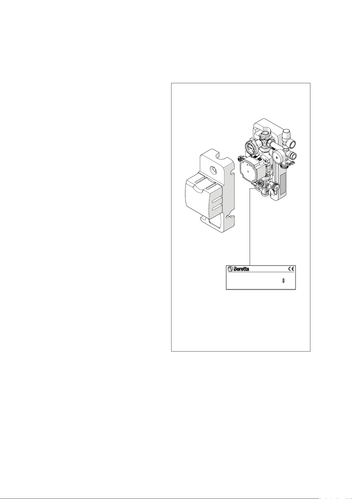
RANGE
MODEL CODE
CONNECT SOLAR R - 7,5m 20116162
Dear heating engineer,
We would like to congratulate you on having recommended
a Bsolar station unit: a modern product that's capable
of ensuring a high degree of reliability, efciency, quality
and safety.
While your technical skills and knowledge will certainly be
more than sufcient, this booklet contains all the informa-
tion that we have deemed necessary for the device's cor-
rect and easy installation.
Thank you again, and keep up the good work,
Beretta
CONTENTS
ENGLISH
1 GENERAL SAFETY INFORMATION
b
Check that the product is complete, undamaged and
as ordered as soon as you receive it. Report any dis-
crepancies or damage to the Bdealer who sold
it.
b
This product must be installed by a legally qualied
heating engineer. On completion of the installation,
the installer must issue the owner with a declaration
of conformity conrming that the installation has been
completed to the highest standards in compliance
with the instructions provided by Bin this instruc-
tion manual, and that it conforms to all applicable
laws and standards.
b
This product must only be used for the purpose
for which it is designed and made, as specied by
B. Bdeclines all responsibility, contractual or
other, for damage to property or injury to persons or
animals caused by improper installation, adjustment,
maintenance or use.
b
The product must be serviced at least once a year.
Servicing must be arranged in advance with the
BTechnical Assistance Centre.
b
All servicing and repairs must be performed by a
qualied heating engineer.
b
This instruction manual is an integral part of the prod-
uct. It must be kept safe and must ALWAYS accom-
pany the product, even if it is sold to another owner or
transferred to another user or to another installation.
If you lose this manual, order a replacement immedi-
ately. Keep the product purchase documents to be
presented to the Bauthorised Technical Assis-
tance Centre to request a service call under warranty.
b
Size the solar expansion tank so as to ensure com-
plete absorption of the expansion of the uid con-
tained within the system, with reference to the prevail-
ing regulations on the matter. In particular, consider
uid characteristics, considerable uctuation of ser-
vice temperature and vapour that might be generated
during solar collector stagnation stage. Proper size
of expansion tank ensures setting off of all volume
changes of the heat transfer uid, avoiding excessive
pressure increase. Limited pressure changes avoid
reaching safety valve opening pressure and the con-
sequent uid drainage.
Generalinformation
The following symbols are used in this manual:
b
CAUTION! =
Identies actions that require caution
and adequate preparation.
a
STOP! =
Identies actions that you MUST NOT do.
Thismanual,Code
-Rev.
comprises
pages.
GENERAL INFORMATION . . . . . . . . . . . . . . . . . . . . . 2
1 General Safety Information . . . . . . . . . . . . . . . . . 2
2 Precautions . . . . . . . . . . . . . . . . . . . . . . . . . . . . . 3
3 Description of the appliance . . . . . . . . . . . . . . . . 3
4 Safety and control devices . . . . . . . . . . . . . . . . . 3
5 Identication . . . . . . . . . . . . . . . . . . . . . . . . . . . . 3
6 System layout. . . . . . . . . . . . . . . . . . . . . . . . . . . . 4
7 Technical specications . . . . . . . . . . . . . . . . . . . 4
INSTALLATION . . . . . . . . . . . . . . . . . . . . . . . . . . . . . . 5
8 Unpacking the product . . . . . . . . . . . . . . . . . . . . 5
9 Installation premises . . . . . . . . . . . . . . . . . . . . . . 5
10 Assembly . . . . . . . . . . . . . . . . . . . . . . . . . . . . . . . 5
11 Water connections . . . . . . . . . . . . . . . . . . . . . . . . 6
12 Pump controller . . . . . . . . . . . . . . . . . . . . . . . . . . 6
13 Electrical connections . . . . . . . . . . . . . . . . . . . . . 8
COMMISSIONING AND MAINTENANCE . . . . . . . . . . 9
14 System ushing . . . . . . . . . . . . . . . . . . . . . . . . . . 9
15 System lling cock . . . . . . . . . . . . . . . . . . . . . . . 10
16 Device cleaning and maintenance . . . . . . . . . . 11
17 Interventions on the hydraulic system . . . . . . . . 11
18 Recycling and disposal . . . . . . . . . . . . . . . . . . . 11