Bergeon 5700-BP User manual
Tél. + 41 32 933 60 00 www.bergeon.ch
Fax + 41 32 933 60 01 [email protected]
Depuis 1 7 9 1
13/01/12
11 / 7004 J1
No 5700-BP 2.700 Kg Pce Fr.
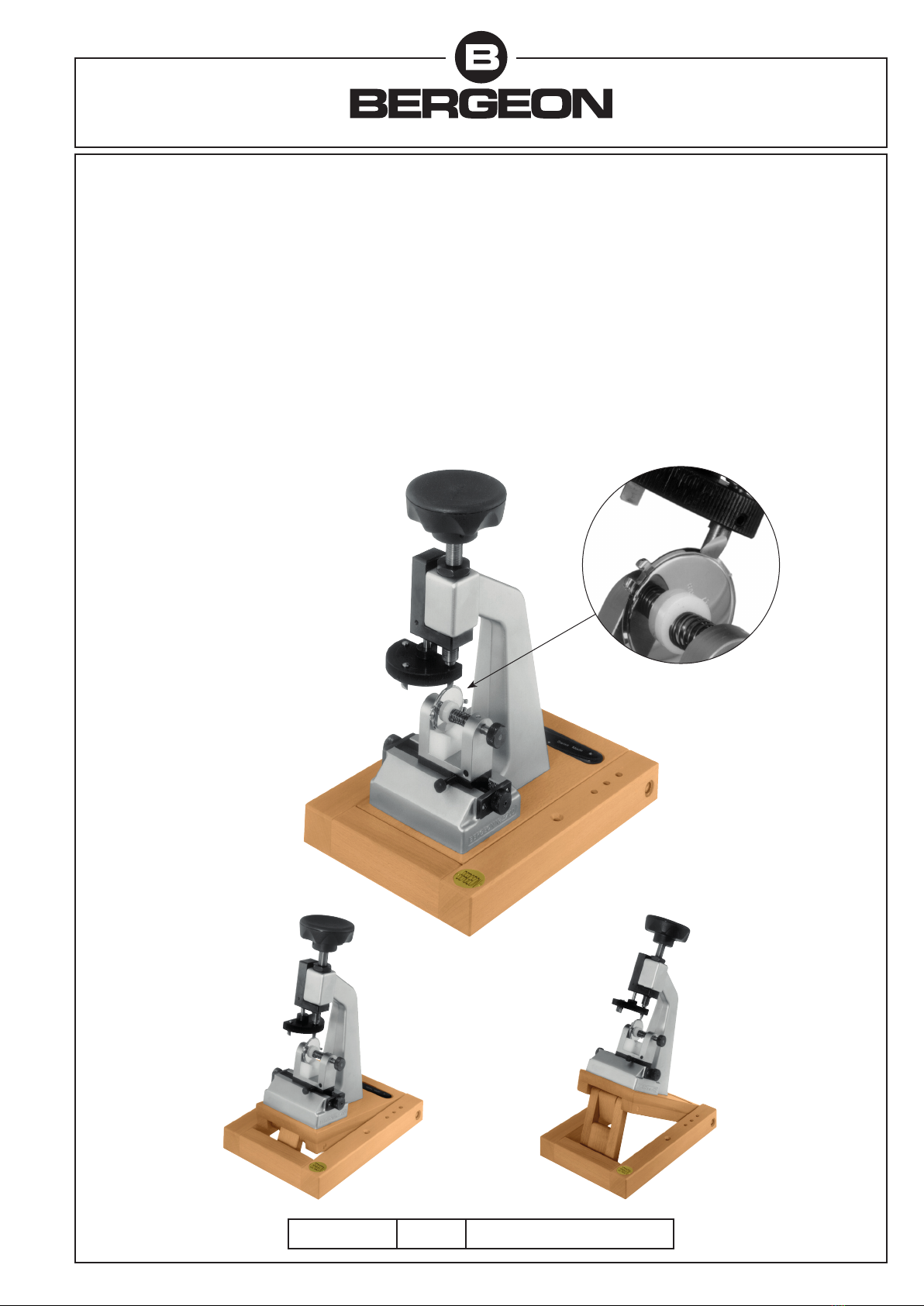
Inclinaison 150pour utilisation
sur établi.
Neigung 150 zur Verwendung
auf dem Werktisch.
Angle 150for use on the
work-bench.
Inclinación de 150para la
utilización sobre banco.
Inclinaison 350pour utilisation
sur table.
Neigung 350 zur Verwendung
auf dem Tisch.
Angle 350for use on the table.
Inclinación de 350para la
utilización sobre mesa.
Pos. 00
Pos. 150
Pos. 350
Potence pour ouvrir
les fonds de boîtes à
pression
Construction rigide en aluminium
injecté, chromé.
– Munie de 3 lames en acier
trempé et poli,
angle 250,350,450.
– Transmission de la force par
vis à pas fin.
– Etau de précision avec
mâchoires ressort.
– 3 supports en nylon pour
boîtes de différentes grandeurs.
– Socle en bois dur, traité,
3 positions de travail 00,150,350.
– 1 ouvre-boîtes No 6403.
Accessoires voir planche
No 7004-J2.
Device for opening
wrist-watch cases with
pressure back
Solid built on aluminium cast-alloy
base, chromed.
– Provided with 3 blades in tem-
pered and polished steel with
angles of 250,350,450.
– Power transmission by screw
with thin pitch.
– Precision vice with spring
jaws.
– 3 nylon case-rest for different
sizes.
– Treated hard-wood base,
3 work positions 00,150,350.
– 1 case opener No 6403.
Accessories see page 7004-J2.
Presstock zum Öffnen
von eingepressten
Gehäuseböden
Solide Konstruktion aus
Aluminiumguss, verchromt.
– Ausgerüstet mit 3 Klingen aus
gehärtetem und poliertem Stahl,
Winkel von 250,350,450.
– Kraftübertragung durch
Feingewindeschraube.
– Präzisionsschraubstock mit
gefederten Backen.
– 3 Nylon-Halter für Gehäuse
unterschiedlicher Grössen.
– Sockel aus behandeltem
Hartholz, 3 Arbeitspositionen:
00,150,350.
– 1 Gehäuseöffner Nr. 6403.
Zubehör siehe Seite Nr. 7004-J2.
Máquina para abrir
cajas de reloj de pulsera
a presión
Construcción sólida sobre una base
de aluminio inyectado cromado.
– Provista de 3 cuchillas de acero
templado y pulido,
ángulos de 250,350,450.
– Trasmisión de fuerza mediante
tornillo de paso fino.
– Tornillo de precisión con
mordazas y muelle.
– 3 soportes de nilón para
diferentes tamaños.
– Base de madera dura,
3 posiciones de trabajo
00,150,350.
– 1 abre cajas No 6403.
Accessorios ver pagina 7004-J2.
www.bergeon.ch Tél. + 41 32 933 60 00
Depuis 1 7 9 1
13/01/12
7004 J2 / 11
No 5700-BP-L 3 gr. Pce Fr.
No 5700-BP-S 5 gr. Pce Fr.
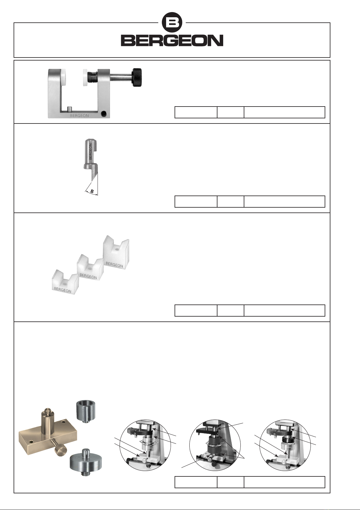
Lames 250, 350, 450
En commandant: Préciser l’angle B. Autres formes sur demande.
Klingen 250, 350, 450
Bei Bestellung: Winkel B angeben. Andere Formen auf Anfrage.
Blades 250, 350, 450
When ordering: Indicate angle B. Other sizes available on request.
Cuchillas 250, 350, 450
Al encargo: Precisar el ángulo B. Otras formas disponibles por encargo.
Supports nylon
Hauteur: 10, 15, 20 mm. En commandant: Préciser la hauteur.
Autres formes et matières sur demande.
Nylon-Halter
Höhe: 10, 15, 20 mm. Bei Bestellung: Höhe angeben.
Andere Formen und Materialien auf Anfrage
Supports nylon
Height: 10, 15, 20 mm. When ordering: Indicate the height.
Other sizes and materials available on request.
Soportes de nilón
Altura: 10, 15, 20 mm. Al encargo: Precisar el altura.
Otras formas y materiales disponibles por encargo
No 5700-BP-E 170 gr. Pce Fr.
Etau
Schraubstock
Vice
Tornillo
2 x D
C
Set d’accessoires
Pour fermer les boîtes de
montres à pression et poser ou
enlever les verres synthétiques
avec ou sans bague de tension.
Utiliser les tasseaux en PVC ou
aluminium dans les planches
No 7006 L / M / U / V.
B
Poser ou enlever les verres synthétiques avec ou sans
bague de tension
Setzen oder abnehmen der unzerbrechlicher, Gläser mit o.
ohne Spannring
To fit or to remove synthetic glasses with tension rings
Colocar o retirar los vidrios sintéticos con, o sin aro de tensión
Fermer les fonds de boîtes à pres-
sion
Schliessen der Druckgehäuse
To close pressure back cases
Cerrar los fondos de cajas a presión
C
B
Ergänzungssatz
Um Druckuhrgehäuse zu schlies-
sen und unzerbrechliche Gläser,
mit oder ohne Spannring einzu-
zetzen.
Einsätze auf PVC oder Aluminium
-Seiten Nr. 7006 L / M / U / V
benutzen.
Set of accessories
To close back pressure back of
watch cases and fit umbeakable
crystals with and without ring.
To be used with the stakein PVC
and aluminium in the pages
No 7006 L / M / U / V.
Juego de accesorios
Para cerrar las cajas de relojes a
presión y colocar o retirar los
vidrios sintéticos con o sin aro de
tensión.
Se utilizá con los tases en PVC y
aluminium en la página No 7006
L / M /U / V.
ADA
B
A2xD
C
No 5700-SET 90 gr. Pce Fr

Tél. + 41 32 933 60 00 www.bergeon.ch
Fax + 41 32 933 60 01 [email protected]
Depuis 1 7 9 1
13/01/12
11 / 7004 J3
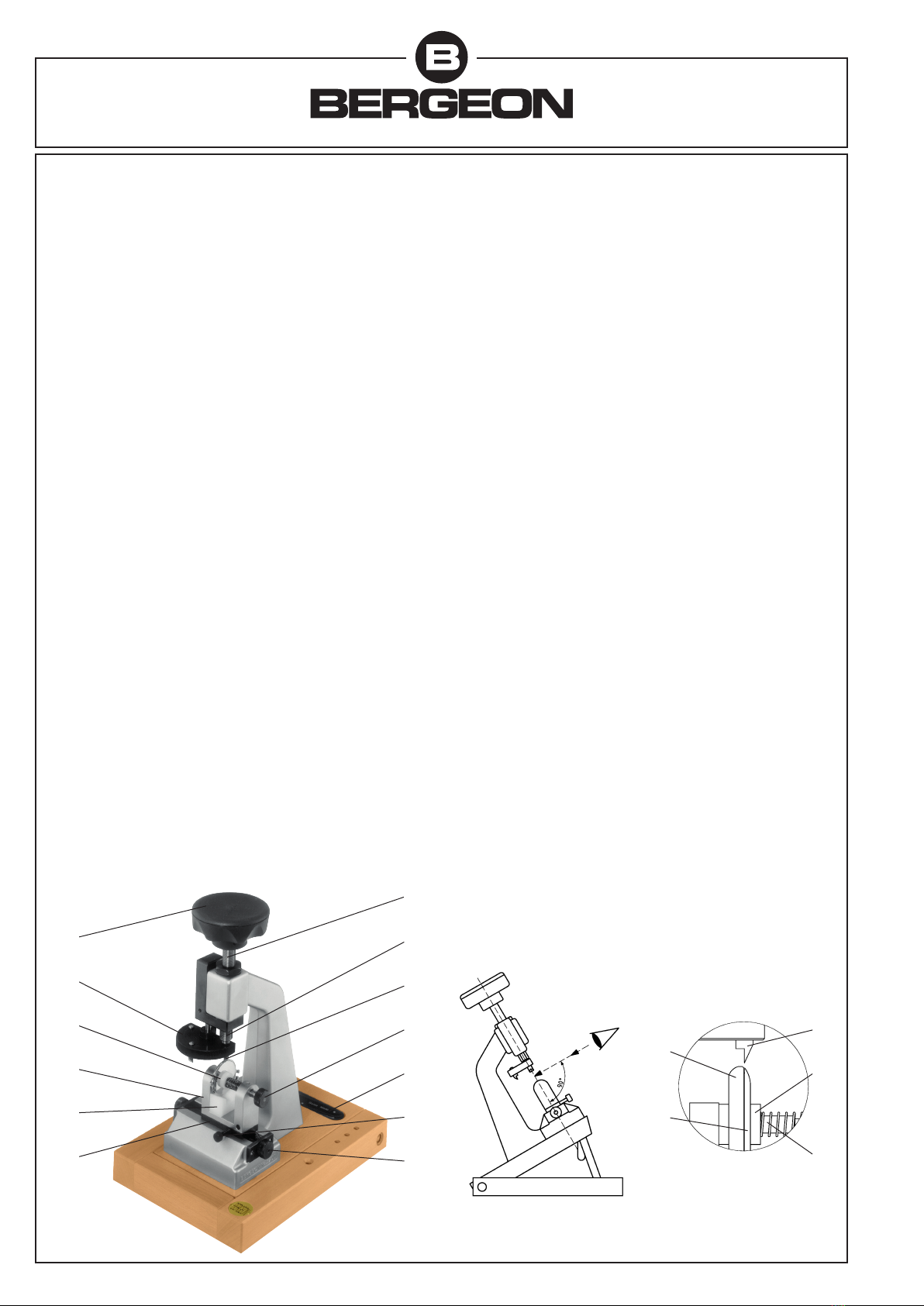
Mode d’emploi
A) Choix de la position de travail (pl. 210)
Inclinaison 00.
Inclinaison 150pour utilisation sur établi.
Inclinaison 350pour utilisation sur table.
Pour une position de travail optimale, la potence doit être perpendicu-
laire au plan de vue selon la figure (a).
B) Extraction de l’étau de son support
Placer le carrousel (1) en position haute, en libérant la lame (2) en
prise. L’étau (4) est maintenu par deux goupilles. L’extraire en le tirant
verticalement.
C) Ouverture de l’étau
Ouvrir la mâchoire de l’étau en tirant l’axe à tête moletée (5). La bloquer
ouverte en effectuant 1/4 de tour lorsqu’elle est en bout de course.
D) Choix du support nylon adéquat
L’appareil est fourni avec 3 supports en nylon (6) de hauteurs différentes:
Support bas: pour boîtes de montre de ∅ 20 jusqu’à ∅ 27 mm.
Support moyen: pour boîtes de montre de ∅ 27 jusqu’à ∅ 35 mm.
Support haut: pour boîtes de montre de ∅ 35 jusqu’à ∅ 45 mm.
Ces valeurs sont données à titre indicatif. Pour un fonctionnement
correct de l’appareil, le fond (14) de la boîte de montre doit se trouver
contre la mâchoire et être centré au mieux par rapport aux rondelles
d’appui (7) selon la figure (b).
E) Fermeture de l’étau et mise en place sur son support
Fermer l’étau en tournant l’axe à tête moletée jusqu’à ce qu’il se libère.
Veiller à le maintenir jusqu’au contact avec le fond de la boîte.
Positionner l’étau sur son support (8) en l’ajustant sur les deux goupilles.
F) Choix de la lame
L’appareil est équipé de 3 lames ayant un angle d’attaque différent 250,
350et 450montées sur le carrousel. En cas d’hésitation, nous conseillons
d’utiliser, dans un premier temps, la lame ayant un angle de 250.
Si le fond n’est pas totalement extrait, utiliser une lame avec un angle
plus important.
G) Réglage de la position horizontale de l’étau
Faire descendre le carrousel à l’aide du volant à lobes (9) fixé au bout
de la vis à pas fin (3). Régler la position horizontale de l’étau à l’aide
des boutons moletés (10).
Se rapprocher avec un maximum de précision au-dessus de l’espace
entre la carrure (15) et le fond (14) selon la figure (b). Figer la position
de l’étau en serrant la vis à tête moletée (11).
H) Ouverture de la boîte
La vis à pas fin, transmettant la force, est équipée d’un système de
compensation (12) monté sur ressort. Celui-ci permet à la lame de
prendre une position correcte en cas de réglage imprécis.
Faire descendre doucement le carrousel à l’aide du volant à lobes tout
en vérifiant que la lame se positionne correctement. Si ce n’est pas le
cas, améliorer la précision du réglage selon G). Ensuite, continuer à
descendre jusqu’à ce que le jeu du système de compensation soit
totalement rattrapé et que le fond de la boîte soit dégagé de la carrure.
Remonter la lame jusqu’à ce que la boîte soit libérée.
Extraire l’étau de son support selon B). Tout en maintenant la carrure
et le fond, ouvrir l’étau selon C).
Au cas où le fond n’est pas totalement dégagé, utiliser l’ouvre-boîtes
Bergeon (13) fourni avec l’appareil.
Gebrauchsanweisung
A) Auswählen der Arbeitsposition (S. 210)
Neigung 00.
Neigung 150zur Verwendung auf dem Werktisch.
Neigung 350zur Verwendung auf dem Tisch.
Für eine optimale Arbeitsposition, muss der Presstock senkrecht zum
Sichtplan nach Abbildung (a) stehen.
B) Herausheben des Schraubstockes aus seinem Halter
Das Karussel (1) in die obere Stellung bringen, indem man die Klinge
(2) frei setzt. Der Schraubstock (4) wird durch zwei Stifte gehalten.
Letzteren senkrecht nach oben herausziehen.
C) Oeffnen des Schraubstockes
Die Schraubstockbacken öffnen, indem man die Achse mit geriffeltem
Kopf (5) herauszieht. Man blockiert, indem man 1/4-Drehung vornimmt.
D) Auswählen des entsprechenden Nylonhalters
Der Apparat wird mit 3 Nylon-Haltern (6) in verschiedenen Höhen geliefert:
Niedriger Halter: für Uhrgehäuse im ∅ 20 bis ∅ 27 mm.
Mittlerer Halter: für Uhrgehäuse im ∅ 27 bis ∅ 35 mm.
Hoher Halter: für Uhrgehäuse im ∅ 35 bis ∅ 45 mm.
Diese Werte dienen nur zum Hinweis. Damit der Apparat richtig
funktioniert, muss der Uhrgehäuseboden (14) an den Backen anliegen
und gegenüber den Auflegeschieben (7) so gut wie möglich zentriert
sein, siehe Abbildung (b).
E) Schliessen des Schraubstockes und Einsetzen in seinen Halter
Den Schraubstock schliessen, indem man die Achse mit geriffeltem
Kopf dreht, bis er frei ist. Darauf achten, dass man ihn bis zum Kontakt
mit dem Uhrgehäuse festhält. Den Schraubstock auf seinen Halter (8)
setzen und seine Position den beiden Stiften anpassen.
F) Auswählen der Klingen
Der Apparat wird mit 3 Klingen mit unterschiedlichem Angriffswinkel
geliefert: 250350und 450. Diese werden am Karussell montiert. Bei
Zweifel raten wir, zunächst einmal die Klinge mit dem Winkel 250zu
verwenden. Wenn diese Klinge den Boden nicht vollständig ablöst,
eine Klinge mit spitzerem Winkel zu verwenden.
G) Regulieren der horizontalen Ausrichtung des Schraubstocks
Das Karussell mit Hilfe des Rades (9) am Ende der Feingewindeschraube
(3) senken. Die horizontale Position des Schraubstocks mit Hilfe der
geriffelten Knöpfe (10) regulieren. Die Klinge so präzise wie möglich
der Fuge zwischen Mittelteil (15) und Boden (14) entsprechend der
Abbildung (b) nähern. Die Position des Schraubstockes feststellen,
indem man die Schraube mit geriffeltem Kopf (11) festzieht.
H) Oeffnen des Gehäuses
Die Feingewindeschraube zur Kraftübertragung ist mit einem
Ausgleichssystem (12) ausgerüstet, das auf eine Feder montiert ist.
Dieses ermöglicht bei ungenauer Regulierung eine Stellungskorrektur
der Klinge.
Das Karussell langsam mit Hilfe des Rades senken und dabei die
Korrekte Stellung der Klinge überprüfen. Gegebenenfalls die Regulie-
rungsgenauigkeit wie G). beschrieben korrigieren. Ansonsten die
Klinge weiter ansenken, bis das Spiel des Ausgleichssystems erschöpft
ist und sich der Boden vom gehäuse ablöst. Die Klinge wieder anhe-
ben, bis das Gehäuse freikommt.
Den Schraubstock wie B) und C) beschrieben aus seinem Halter
herausnehmen.
Falls der Boden nicht ganz abgelöst ist, den Gehäuseöffner Bergeon
(13) verwenden, der mit dem Apparat geliefert wird.
Figure (a) Figure (b)
912
2
5
13
11
10
3
1
7
4
6
8
15
14
www.bergeon.ch Tél. + 41 32 933 60 00
Depuis 1 7 9 1
13/01/12
7004 J4 / 11
Directions for use
A) Choice of the work position (pl. 210)
Angle 00.
Angle 150for use on bench.
Angle 350˚ for use on table.
For a good work position, the press must be perpendicular to the
plan-view, according to the drawing (a).
B) Extraction of the vice from its rest
Put the karussel (1) in uppermost position, by releasing the blade (2)
in gear. The vice (4) is kept by two pins. Remove it by pulling it upwards.
C) Opening of the vice
Open the vice jaw by pulling the arbor with knurled head (5). Stop it
open by making 1/4 turn when it is at full stroke.
D) Choice of the suitable nylon support
The device is supplied with 3 nylon supports (6) of different heights:
Low support: for watch-cases from ∅ 20 to ∅ 27 mm.
Middle support: for watch-cases from ∅ 27 to ∅ 35 mm.
Upper support: for watch-cases from ∅ 35 to ∅ 45 mm.
These values are given as indicative estimation. For a correct running
of the device, the back of the watch-case (14) must be against the jaw
and well adjusted with regard to the support washers (7), according to
the drawing (b).
E) Closing of the vice and setting on its rest
Close the vice by turning the arbor with knurled head until its releas-
ing. Be careful to keep it until the contact with the case back. Put the
vice on its rest (8) by adjusting it on the two pins.
F) Choice of the blade
The device is equipped with 3 blades which have a different bite angle
250, 350and 450mounted on the karussel. In case of hesitation, we rec-
ommend to use, in a first time, the blade with an angle of 250. If the
back is not completely removed, use a blade with a most important
angle.
G) Setting of the horizontal position of the vice
Get the karussel down with the hand-wheel (9) fixed at the end of the
screw with a fine pitch (3). Set the horizontal position of the vice with
the knurled buttons (10).
Go closer, with care, above the space between the middle (15) of
watch-case and the back (14), according the drawing (b). Keep the
position of the vice by tightening the screw with knurled head (11).
H) Opening of the watch-case
The screw with the fine pitch, which transmitts the power, is equipped
with a compensation system (12) mounted on spring. This one allows
the blade to get a correct position in case of unprecise setting.
Get the karussel down slowly with the hand-wheel by checking if the
blade sets correctly. If it is not the case, improve the precision of the
setting, according to G). If it is the case, continue to get down until the
set of the compensation system is completely catched up and the case
back comes out of the middle of watch-case.
Lift the blade until the case is released.
Remove the vice from its rest, according to B). By keeping the middle
of the watch-case and the back, open the vice, according to C).
If the back is not completely removed, use the Bergeon case opener
(13), which is supplied with the device.
Modo de empleo
A) Selección de la posición de trabajo (pl. 210)
Inclinación 00.
Inclinación 150para utilización sobre banco.
Inclinación 350para utilización sobre mesa.
Para obtener una posición de trabajo óptima, la potenza tiene que estar
perpendicular al plano de vista según la figura (a).
B) Extracción del tornillo de su soporte
Poner el torniquete (1) en posición alta, liberando la cuchilla (2) sostenida.
El tornillo (4) está mantenido por dos clavijas. Extraerlo tirandola
verticalmente.
C) Apertura del tornillo
Abrir las mordazas del tornillo tirando del botón moleteado (5).
Bloquearlas abiertas efectuando 1/4 de vuelta al final del recorrido del
botón moleteado.
D) Selección del soporte de nilón adecuado
El aparato está entregado con 3 soportes de nilón (6) de alturas diferentes:
Soporte bajo: para cajas de reloj de ∅ 20 hasta ∅ 27 mm.
Soporte mediano: para cajas de reloj de ∅ 27 hasta ∅ 35 mm.
Soporte alto: para cajas de reloj de ∅ 35 hasta ∅ 45 mm.
Estos datos son indicativos. Para un funcionamiento correcto del
aparato, el fondo (14) de la caja del reloj debe apoyarse contra las
mordazas y estar centrado lo mejor posible respecto a las arandelas
de apoyo (7) según figura (b).
E) Cerradura del tornillo y puesta en su sitio sobre el soporte
Cerrar el tornillo girando el eje del botón moleteado hasta liberarlo.
Cuidado en mantenerlo hasta que llegue en contacto con el fondo de
la caja. Posicionar el tornillo sobre su soporte (8) ajustandolo sobre
las dos clavijas.
F) Selección del cuchilla
El aparato está equipado con 3 cuchillas de diferentes ángulo de
ataque: 250, 350y 450montadas sobre el torniquete. En caso de duda,
se aconseja usar, en primer lugar, la cuchilla de ángulo de 250.
Si el fondo no está totalmente extraído, se acanseja utilizar una cuchilla
con ángulo mayar.
G) Ajuste de la posición horizontal del tornillo
Hacer bajar el torniquete con la ayuda del volante (9) fijado al final del
tornillo con paso fino (3). Ajustar la posición horizontal del tornillo con
la ayuda de los dos botones moleteados (10). Apróximarse con una
máxima precisión encima del espacio entre la caja (15) y el fondo (14)
según figura (b). Inmovilizar la posición del tornillo apretando el tornillo
moleteado (11).
H) Apertura de la caja
El tornillo con paso fino que transmite la fuerza está equipado de un
sistema de compensación (12) montado sobre un muelle. Este último
permite a la cuchilla adoptar una posición correcta en caso de ajuste
impreciso.
Hacer bajar lentamente el torniquete con la ayuda del volante,
comprobando que la cuchilla se posicione correctamente. Si no es el
caso, mejorar la posición del ajuste siguiendo las instrucciones G). Si es
así, seguir bajando hasta que el juego del sistema de compensación
esté totalmente recobrado y que el fondo se extraiga de la caja.
Subir la cuchilla hasta que la caja quede despejada. Sacar el tornillo de
su soporte seguiendo las instrucciones B). Sosteniendo la caja y el fondo,
abrir el tornillo siguiendo las instrucciones C).
En caso de que el fondo no esté totalmente extraído, utilizar el abre
cajas Bergeon (13) suministrado con este aparato.
Figure (a) Figure (b)
912
2
5
13
11
10
3
1
7
4
6
8
15
14
2
7
5
Other Bergeon Tools manuals


