Bergey XL-15 User guide

Page 1 of 28
REV 0.1
BERGEY XL-15 INSTALLATION QUICK GUIDE

Page 2 of 28
REV 0.1
TABLE OF CONTENTS
RECOMMEND TOOL LIST………………………………………………………………………………………4
TORQUE VALUES……………………………………………………………………………………………….…5
TURBINE HARDWARE……………………………………………………………………………………………6
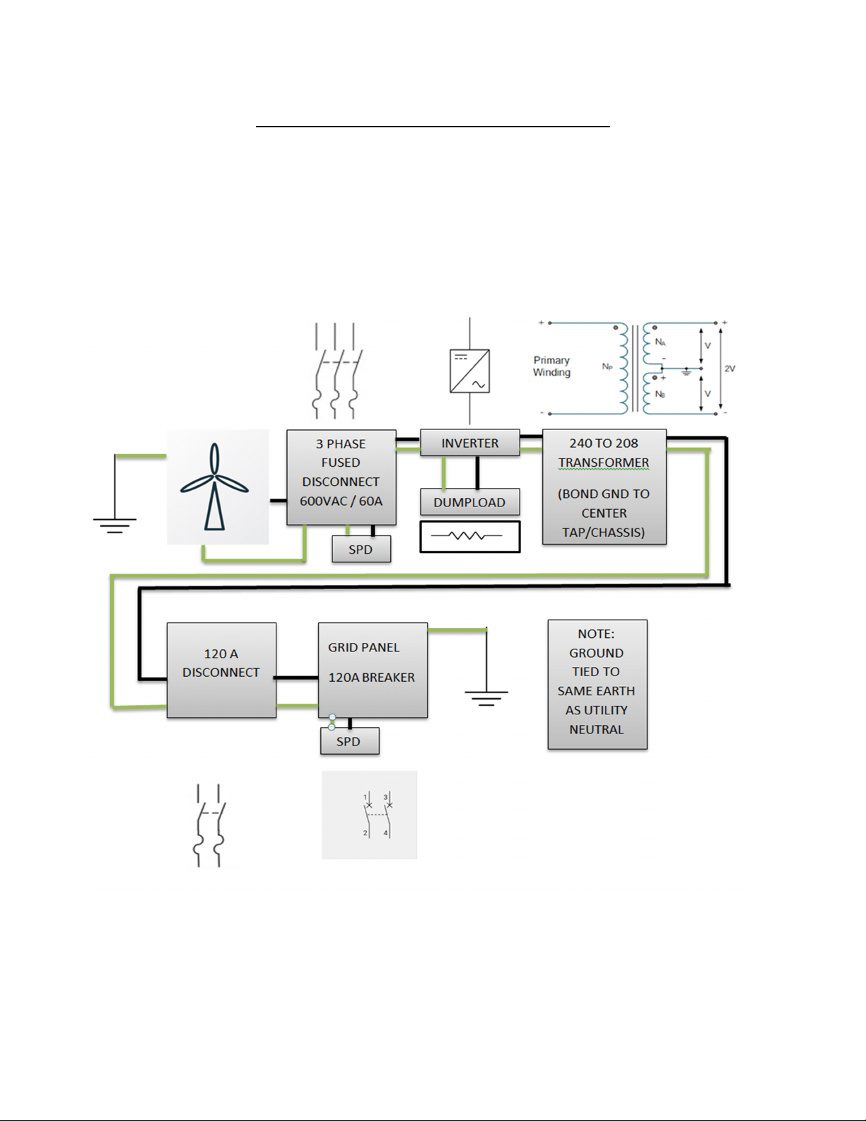
ELECTRICAL STANDARD 240VAC…………………………………………………………………………..7
ELECRICAL TRANSFORMER REQUIRED………………………………………………………………….8
WIRE SIZE CHART…………………………………………………………………………………………………9
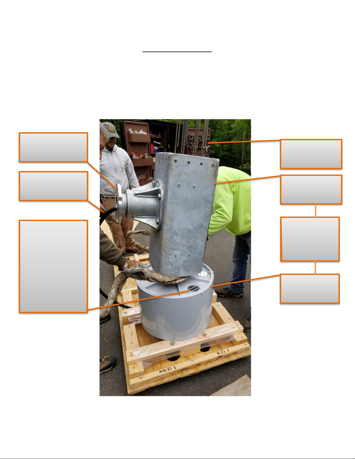
GETTING STARTED………………………………………………………………………………………………10
POSITIONING THE UNIT FOR TAIL ASSEMBLY…………………………………………………….11
TAIL INSTALLATION………………………………………………………………………………………12-13
TAIL FIN INSTALLATION………………………………………………………………………………………14
RIGGING THE TURBINE FOR THE LIFT…………………………………………………………………15
BLADE INSTALLATION…………………………………………………………………………………………16
CLAMP PLATE SPACERS…………………………………………………………………………….17
BLADE ORIENTATION………………………………………………………………………………..18
FITTING BLADES………………………………………………………………………………………..19
BLADE TORQUE…………………………………………………………………………………………20
NOSE CONE INSTALLATION…………………………………………………………………………………21
APPLYING A PHASE TO PHASE SHORT…………………………………………………………………22
RAISING THE TURBINE………………………………………………………………………………………..23

Page 3 of 28
REV 0.1
SYSTEM COMMISSIONING ……………….………………………………………………………………..24
MEGGER TEST……………………………………………………………………………………….….24
INVERTER/DUMPLOAD …………………………………………………………………………...25
ALTERNATOR OUTPUT……………………………………………………………………………..26
SYSTEM COMMISSIONING CHECKLIST………………………………………………………27
ADDITIONAL INFORMATION……………………………………………………………………………….28
***BEFORE PERFORMING ANY LIFTING OPERATION ENSURE ALL PARTS
ARE FREE AND CLEAR FROM OBSTRUCTIONS AND ARMORED CABLE
WILL NOT BE CRUSHED OR DEFORMED IN ANY WAY***

Page 4 of 28
REV 0.1
RECOMMENDED TOOL LIST
Please note the below list is to serve as a general reference of what tools you
should have available. However in no way is it meant to be a comprehensive list
of tools required to complete the installation.
Torque wrench -150 FT LBS
1-1/16 deep socket
17 MM socket and wrench
24 MM socket
22 MM socket
5/32 or 4MM allen key
Screw drivers
Wire strippers
Wire crimpers
Diagonal cutters
Razor blade knife
Drill bits
Volt meter/megger
Spud wrench
Tag line
Chain hoist

Page 5 of 28
REV 0.1
TORQUE VALUES
TASK
TOOL
HARDWARE
TORQUE
Attach tailboom to mainframe
17 MM
10
MM
35
ft⋅lb
Attach tailfin to tailboom
17 MM
10 MM
35
ft⋅lb
Torque bracket to alternator
24
MM
16
MM
100
ft⋅lb
Blades/clamp plate to alternator
24 MM
16 MM
*SEE PG
20
Spinner mounting
17 MM
10 MM
20
ft⋅lb
Turbine to tower
1
-
1/16”
5/8 (UNC)
120
ft⋅lb
(wax)
198-240 ft⋅lb
Inverter grid side connections
5/32 or 4mm
allen key
90 inch lbs
Inverter Turbine side connections
#2 flathead
screwdriver
40 inch lbs
Dumpload +/- connections
3/16” or
5MM
90 inch lbs
Dumpload fan connections
Wire
crimpers
Butt splice

Page 6 of 28
REV 0.1
TURBINE HARDWARE

Page 7 of 28
REV 0.1
ELECTRICAL –STANDARD 240VAC 60Hz
This is how a typical 240 VAC grid tied installation will look once installed. For
deviation to the one line follow all local codes.

Page 8 of 28
REV 0.1
ELECTRICAL TRANSFORMER REQUIRED
This configuration is typical for a grid tied system that is not a standard 240VAC. A
25KVA transformer is sized appropriately. A number of manufactures make
transformers that are suitable for installation. For this example we will use the
single phase transformer from Maddox.
208 – 120/240: MIT-DRY-224 (25 KVA)
240 / 480 – 120/240: MIT-DRY – 120 (25 KVA)
NOTE: The 120A fused disconnect is not mandatory but could be required by local
code.

Page 9 of 28
REV 0.1
WIRE SIZING
Recommended Wire Size for BWC EXCEL 15 Installations
Note that wire run lengths correspond to performance values estimated by
WindCAD. Annual Energy Output losses of 4.5% were factored into the WindCAD
model to account for energy losses due to wire sizing.

Page 10 of 28
REV 0.1
GETTING STARTED
The unit will come in three packages. Below is the power head crate that has
been open and stripped down to begin turbine assembly. Note the alternator is
bolted to the pallet.
Mainframe
The mainframe
and alternator
combined is a
powerhead
Alternator
Brake resistors
Tower adapter
Rigid armor cable
WARNING: The
alternator louvers
must be covered if
any moisture could
accumulate on the
back of the alternator
while stored in this
position.

Page 11 of 28
REV 0.1
POSITIONING THE UNIT FOR TAIL ASSEMBLY
A mechanical advantage will be required to lower the powerhead on its side as it
weights over 1,000 lbs. Careful attention must be given to the armored cable and
brake resistors to ensure this is not crushed in the process. Damage to the
armored cable could result in a non-operational turbine.

Page 12 of 28
REV 0.1
TAIL INSTALLATION
Take caution to ensure the tail is not installed upside down, note it will bolt on
incorrectly. Leave all bolts finger tight until all bolts are started. Ensure extreme
caution is taken to avoid damaging the brake resistors protruding from the rear of
the mainframe when joining mainframe and tail together.
WARNING: The tailboom
bolts must be installed with
hand tools. Using an impact
driver WILL damage the
nuts.
Tailboom incorrectly
installed upside down

Page 13 of 28
REV 0.1
TAIL INSTALLATION CONTINUED
A quick check to ensure you are installing the tailboom correctly: While looking
down the turbine, from the alternator to the tailboom the tail fin should be
located on the right side of the machine.
Tailboom installed correctly

Page 14 of 28
REV 0.1
TAIL FIN INSTALLTION
Shown below are images of how it will look after proper installation.

Page 15 of 28
REV 0.1
RIGGING THE TURBINE FOR THE LIFT
The turbine has two eye bolts atop the mainframe. Ideally a separate strap is
attached to each eye bolt. It has been reported when picked in this manner the
tower adapter does not “sit” parallel with the tower top. A chain hoist can
provide for fine adjustments.
Lift Weight: ~1,350 LBS
Tag line to
control
turbine
swing
Blades should not be
installed yet. However, take
note of blade orientation,
with one blade straight up

Page 16 of 28
REV 0.1
BLADE INSTALLATION
Blade clamp
plate
T
orque
brackets
Blade

Page 17 of 28
REV 0.1
TORQUE BRACKETS
Install the blade clamp plate and the torque brackets. Notice the bolt goes
through the clamp plate then through the plate spacers into the alternator. Leave
all hardware loose.
NOTE: The clamp
plate spacers are
from a previous
revision. Current
production will
have hardware to
mount the nose
cone already
installed

Page 18 of 28
REV 0.1
BLADE ORIENTATION
The blades can bolt onto the alternator backwards. It is import to ensure this does
not happen. Although the blades come with stickers that indicate which side of
blade root should face the alternator, close scrutiny should be applied to ensure
they are correct. When facing the alternator looking towards the tailboom the
blades should rotate counterclockwise. The leading edge (thick) portion should
turn into the wind.
Spinner
attachment
hardware is
not current
production
Trailing
edge
Leading
edge

Page 19 of 28
REV 0.1
FITTING BLADES
Now that the blade clamp plate and clamp plate spacers are installed loosely. We
can install the first blade. Fit the blade between the alternator and clamp plate as
documented below.
Two blades can be installed before the turbine is lifted. While the turbine is being
lifted they can be rotated around for the easiest installation of the third blade.
Install first blade
Install second blade

Page 20 of 28
REV 0.1
BLADE TORQUE
While lifting the turbine pay attention to the armored cable and ensure that it is
not crushed at any point in the process. The blades have a procedure for being
torqued. Start with 50 ft⋅lb. then back off a ¼ turn, 75 ft⋅lb. then back off a ¼ turn,
100 ft⋅lb. then back off a ¼ turn, 125 ft⋅lb. then back off a ¼ turn and final torque
at 150 ft⋅lb.
At this time the tag line should be installed to assist in raising the turbine.
NOSE CONE INSTALLATION
Table of contents
Other Bergey Wind Turbine manuals